Stability Evaluation of Mobile Robotic Systems using Moment-Height Measure S. Ali A. Moosavian, Khalil Alipour Department of Mechanical Engineering K. N. Toosi Univ. of Technology Tehran, Iran
[email protected] ,
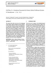
[email protected] tipping-over. For instance this phenomenon can happen when such a mobile robotic system manipulates a heavy object as shown in Fig. 1.
Abstract—Due to excessive maneuverability, mobile manipulators which consist of one or more manipulators mounted on a mobile base have attracted much of interest. Tipping-over is one of the most important problems in such systems especially when manipulating heavy objects, also during maneuvers in unknown environment or in rugged terrains. Therefore, estimation and evaluation of dynamic stability with appropriate easy-computed measure throughout the motion of such systems is a challenging task. In this study, various dynamic stability measures are investigated and compared with each other. Next, a new effective measure named as Moment-Height Stability (MHS) measure is presented for wheeled mobile manipulators. The proposed metric is physically meaningful based on principal concepts, and can be implemented with limited low computational effort. The suggested MHS measure can be effectively used for both legged robots and mobile manipulators. Finally, a few case studies are presented to compare the new MHS measure with the main existing measures. The obtained simulation results show the merits of the new proposed MHS measure, in terms of prediction the exact time of instability occurrence, without additional precautions of the other measures which may confine the maneuverability of the system and its operation.
Therefore, to perform path and trajectory planning in controlling such systems, an instantaneous dynamic stability measure is required. The planning can also be done off-line using a simulation routine. Then, based on a proper stability margin criterion, any critical and hazardous work conditions can be determined to avoid in real work conditions and provide safety of the system and its operator. Besides, such a stability measure can be used in autonomous or unmanned vehicles and teleoperated mobile manipulators operating in unknown environment. Several researchers have tried to propose a suitable criterion for dynamic stability margins. For instance, the shortest distance of center of mass projected to the horizontal plane from the projected support boundary has been used as a measure, [4]. Dubowsky and Vance considered the stability of vehicle as an additional constraint for conventional optimal time trajectory planning, [5]. However they addressed stability against toppling down merely in the case of stationary vehicle. The Zero Moment Point (ZMP) has been presented and used for planning the motion of a redundant manipulator,
Keywords—Mobile Manipulators- Dynamic Stability-Turn over
I. INTRODUCTION Mobile manipulators are used in different kinds of fields such as fire fighting, forestry, dismantling bombs, toxic waste cleanup, transportation of nuclear materials and similar applications. However, locomotion capability causes some problems in design and manufacturing of such systems compared to fixed base manipulator arms. In a mobile robotic system, whether wheeled or free-flying in space, dynamic forces affect the motion of the base and the manipulators, based on the action and reaction principle. The kinematics, dynamics and control of such systems have been described in previous works, [1-3]. One of the most important problems caused by base movement, when the system undergoes a fast maneuver or tries to climb a slopped terrain, is the instability problem or
Figure 1. A mobile manipulator manipulating a heavy object may go unstable.
1-4244-0025-2/06/$20.00 ©2006 IEEE
RAM 2006 97
system. So during the movement of the system, the wheels will not slip and therefore the mobile system is a nonholonomic one. Note that for exploring the stability of the system most of our attention is concentrated on the vehicle pose. When the system is the margin of turning-over the moving base is going to rotate about an axis which is named tip-over axis.
[6]. The ZMP criterion was originally used for gait planning in anthropomorphic robots in which the center-of-mass (c.m.) position is constant. On the other hand, in mobile manipulators especially in manipulating heavy objects the c.m. can be variable. Therefore, the ZMP, in its original form is not sensitive to the variation of c.m. position. Also, if the ZMP is calculated in a way presented in [6], the mass moment of inertia of different rigid bodies will be neglected. Moreover, the ZMP does not provide any specific indication about the system instability at all, [7-8]. The cooperative motion planning consisting of a rough motion planning and a local accurate one considering the dynamic stability of system has been also proposed, [9], where the links of the manipulator and the mobile base are considered as several particles ignoring the mass moment of inertia of them in evaluating the dynamic stability margin. To include the mass moment of inertia the original formulation of ZMP has been modified, [10].
Any rotation of a system is caused by torques or the rotational effect of exerting forces, i.e. moments. It should be noted that in a natural or untripped toppling-down, the vehicle rotates about one of the support pattern edges and in contrast, in a tripped instability (when the vehicle confronts an obstacle or a sudden changes in ground condition) it will tip over about some combination of support pattern edges, [13]. Therefore, it seems rational to define a measure based on the stabilizing and destabilizing moments for both cases. To this end, first consider a simple static planar system which is exerted by two external forces, as shown in Fig. 2. Here, just to reveal the physical concepts, it is assumed that the mobile base is affected by external forces, and a more general case including some exerting torques will be discussed right after. In this case the support boundary polygon is a rectangular, and the following statements can be written:
Another measure employs the resultant moment about each boundary edge based on all external, gravitational and inertial forces, and exerting torques on the system, [11]. A normalization procedure is followed in order to change the unit of the margin to a length unit. But this measure, as will be explained more, is insensitive to the c.m. height in its original form. Another stability criterion has been introduced based on the required energy for placing the c.g. into a plane (called equilibrium plane) such that the whole moment exerted on the system is minimized, [12]. Although this measure incorporates the inertial forces but it assumes a fixed direction for the external and inertial forces and torques relative to machine frame during imaginary rotations of the system. Also, its enormous computation steps require lots of preliminaries. Papadopoulos and Rey have reported another measure named force-angle margin, [13]. This measure uses the minimum angle between resultant force exerted to the base and tip over axis normal subjected to the assumption of low velocities.
the greater (f 2 d 2 − f 1d 1 ) ⇒ the better stability situation is provided if
(1)
f 2d 2 − f 1d 1 = 0 ⇒ The critical case for stability
if
(2)
f 2 d 2 − f 1d 1 < 0 ⇒ The system goes unstable
(3)
If the system operates on a sloped surface or an uneven terrain the above statements will still be true. Therefore, based on this physical intuition, the term “ ( f d − f d ) ” can be employed to establish an effective criterion for dynamic stability/instability evaluation.
In this paper, a new measure named as Moment-Height Stability (MHS) measure is presented for wheeled mobile manipulators, after a brief comparative review of various dynamic stability measures. The proposed metric is physically meaningful based on principal concepts, and can be implemented with limited low computational effort. The suggested MHS measure can be effectively used for both legged robots and mobile manipulators. Finally, a few case studies are presented to compare the new MHS measure with the main existing measures. The obtained simulation results show the merits of the new proposed MHS measure which can be used for on-line planning due to limited computational requirements.
2
2
1
1
III. MOMENT-HEIGHT STABILITY MEASURE In order to extend the explained simple planar static issue to the general spatial dynamic case, we should add the inertial
II. BASIC CONCEPTS The support boundary polygon is defined as the outermost of the base contact points which form a convex support polygon. It should be mentioned that the loss of stability may happen in several ways such as pure sliding, pure rotation about a boundary point and combined sliding and rotation, [7]. In this paper, the case of pure rotation is of interest. Also, the tip-over of the platform will be devoted as instability and hence the yaw instability (which may be experienced in car dynamics) will not be considered as an unstable pose for
Figure 2. A simple two-dimensional static vehicle which is influenced by two external force f 1 and f 2 .
98
force/torque to the external wrench exerted to the system. To this end, consider the more general support polygon shown in Fig. 3. As shown, the support boundary has been considered with six edges, and the coordinate frame x y z has been attached to the base body for computational aspects. The point that the manipulator arm is attached to the base is named ‘F’, which is considered as the origin of the body coordinate frame x y z . Then, to apply the Moment-Height Stability (MHS) measure, the following steps should be executed: 0
0
0
0
(4b)
α,
is computed as
i = {1, 2, … , n}
α = min(α i ) i
(5)
where α i denotes the dynamic stability margin about thy i-th boundary edge and is computed as
(
α i = ( I vi ) . M i ⋅ aˆ i σi
)
i = {1, 2, … , n}
(6)
where I vi is the base moment of inertia about the i-th edge of support boundary edge, and
0
Using the outward iterations, the kinematic analysis of the manipulator arm(s) is completed, and then the inertial forces/torques for each link are computed. Next, through the inward Newton-Euler iterations the kinetics of the manipulator arm(s) is solved, and the wrench exerted on the moving base (or link ‘0’) by the manipulator(s) is computed, and described in the base body coordinate. It should be noted that this wrench reflects the whole effect of the manipulator arm(s) on the mobile base which includes manipulator dynamics, endeffector loading and hand reaction forces due to interaction with the environment. This basic step can be completed off-line by creating a parametric code using a symbolic computation tool like Maple, as it has been accomplished in our case studies, so it will get an ignorable possessing time for on-line exploitations.
(M
⋅ aˆ
+1
; if
−1
; otherwise
σi =
i
i
)>0
i = {1, 2, … , n }
(7)
Note that the MHS measure incorporates the mass moment of inertia of the moving base, which is a significant factor in possible rotation of the moving base. For a stable case, the higher I is, the more secure stability will be. On the other vi
hand, once the system is going unstable, higher I causes a slower tip-over. Thus, the chance for compensation will be improved. In other words, when there are two systems with the same destabilizing moments about their edges, the chance for tip-over compensation for the one which has a higher moment of inertia about its tip-over edge is greater. It should be noted that the inner product between the resultant moments M and aˆ unit vectors implies that if the moment about the i-th edge is vi
i
Considering all forces and torques exerted to the base body due to manipulator motion, gravitational forces, inertial force and external forces/ torques (which are described in the base body frame), the resultant moment about each edge of support boundary is computed. Recall that the effect of manipulator arm has been substituted by a wrench where its components described in the base platform whose origin is point ‘F’. Also the inertia force/torque exerted to the base and weight of the base is considered at c.m. of base. Then the moment of these wrenches about corner points (the vertices of support polygon) can be found. Next the calculated moments about different vertices can be projected easily about different edges of support polygon. These moments about edges 12, 23 …and n1 are named as M , M ,..., M , respectively. 2
p1 − p n
Finally, the dynamic MHS measure, follows:
Consider the platform as the link number ‘0’ and compute the acceleration components of point ‘F’. These components must be described in the body coordinate frame x y z . Also the components of angular velocity related to the base are computed and described in the body frame. 0
(4a)
p1 − p n
aˆ n =
First divide the whole system into two subsystems i.e. the mobile platform and the manipulator arm(s). This division is performed since in determination the MHS measure the basic concentration is on the part which produces mobility that is the mobile base.
0
i = {1, 2, … , n − 1}
p i +1 − p i
0
0
1
p i +1 − p i
aˆ i =
i
stabilizing, then
αi
is positive and if it is destabilizing then it
is negative. When the minimum of all
αi
's, that is
α,
is
n
For each edge of the support polygon a unit vector aˆ is defined such that all the unit vectors make a closed loop direction. In this study, we choose the clockwise direction. If p , p , … , p represent the coordinates of contact points on the ground, described in the base coordinate frame, then the unit vectors of the support boundary edges can be computed as follows: i
1
1
Figure 3. The support boundary and the frame attached to the base body.
positive the system is stable. Conversely, negative values of α displays the instability is in progress. The zero value of α represents the critical dynamic stability. Although with the
n
99
mentioned definition for dynamic stability the importance of stabilizing and destabilizing moments has been addressed, it can be still improved. More specifically, the MHS measure in the above form is not directly sensitive to the height of the whole system center-of-mass as shown in Fig. 4. As shown for a system that carries a variable load and it only experiences merely gravitational forces, the value of α for the two cases of different c.m. height is equal. Whilst due to any applied disturbance the higher c.m. causes easier turn over, so that the system dynamic instability potential will be higher. Therefore, the MHS measure α is improved for direct incorporation of the c.m. height as follows: α = ( hc . m . ) . min(α i )
i = {1, 2, … , n}
λ
i
The mass moments of inertia about different edges of vehicle are as follows: 2
I v = 186.7091(kg.m ) 1
2
I v = 686.7091(kg.m ) 2
Note that the base is considered as a square so that I v = I v 3
−1 +1
4
(8)
i
(9)
The MHS measure α can also be normalized as follows: αˆ =
( hc . m . )
( (h
λ
) ) c . m . nom
( min(α ) ) ( min(α ) ) i
i
λnom
i
i
i = {1, 2, … , n } nom
2
a) First Case . In order to examine which measure is more consistent with the physical concept of instability, a simple motion is considered. Suppose the mobile base with a mass of 500 kg is fixed and does not move. A steel cylinder with a mass of 245.987 kg (diameter = 0.20 m, length = 1.0 m) has been grasped by the end-effecter. Except the second and third joint of the manipulator, the other joints are locked. The moving links travel outside the support polygon such that the system is
; if min(α i ) > 0 ; otherwise
1
and I v = I v . It is assumed that the mobile base moves on a flat terrain. As mentioned before, all calculations have been performed using a symbolic code developed in Maple 6, and the obtained models were transferred to another code in Matlab to complete numerical simulations.
where hc .m . denotes the system c.m. height, and λ=
.
TABLE I.
The specification for the manipulator arm
Parameter
(10)
where αˆ is the normalized dynamic stability margin and subscript "nom" refers to the corresponding nominal value. In this study, the initial pose is considered as nominal configuration. Note that in order to compare different introduced measures, such a normalization procedure will make the comparison a fair and meaningful one.
m1 ,..., m6
85, 32, 8, 2, 2, 2 Kg
The mass of links
L1 ,..., L6
2, 3, 2, 0.09, 0.2, 0.2 ( m)
The lengths of the links
I1
IV. CASE STUDIES AND DISCUSSIONS To compare the MHS measure with the main introduced measures, three cases for movement of the system is considered and analyzed. As shown in Fig. 1, the system consists of a relatively heavy mobile base and a 6 degree-offreedom manipulator arm with the configuration of PUMA 560. Table 1 expresses the complete specifications of the mobile manipulator.
Description
Value (unit)
I2
0 0 26.85 0.43 0 0 0 0 26 . 85 ( Kg .m 2 )
0.0406 −744 E − 8 319 E − 8
−744 E − 8 23.0642 0
0 23.0648
Mass moment of inertia for 1st link
319 E − 8
Mass moment of inertia for 2nd link
( Kg .m 2 )
Figure 4. Insensitivity to the height of the center-of-mass.
100
I3
0 0 0.0035 2.46 0 0 0 0 2 . 46 ( Kg .m 2 )
Mass moment of inertia for 3rd link
I4
0 0 2.1 0 0.00032 0 0 0 2.1 ( Kg .m 2 )
Mass moment of inertia for 4th link
I5
0 0.58 0 0 0.58 0 0 0 0.00035 ( Kg .m 2 )
Mass moment of inertia for 5th link
I6
0 0.58 0 0 0.58 0 0 0 0.00035 ( Kg .m 2 )
Mass moment of inertia for 6th link
Figure 5. Comparison between important stability measures for the first case.
Figure 6. The sensitivity of measures to the system c.m. height during the second maneuver.
going unstable. It can be observed that when the moment about the front axel becomes zero, or the reaction forces at rear tires are getting close to zero, the instability is about to occur. Variation of the MHS measure during such a maneuver, between t = 0 and t = 10 S, is shown in Fig. 5, and compared to the other four important introduced measures which are Energy-Equilibrium Plane [12], Zero-Moment Point (ZMP) [9], Force-Angle [13], and Normal Supporting Force [5].
sensitive, which reveals merits of the MHS measure compared to the others. Both first and second maneuvers have been planned so as the mobile base was fixed, the third case will examine a general maneuver with a moving base. c) Third Case. In this case, we assume that the mobile base with a mass of 500 kg is moving along a circular path. A steel cylinder with a mass of 69.295 kg (diameter = 0.15 m, length = 0.5 m) has been grasped by the end-effector. The first joint of the manipulator, moves the arm under the relation:
As expected, all different measures can realize that the system is going unstable, and as demonstrated the four measures including Force-Angle, ZMP, MHS and Normal supporting force is predicting the accurate time for instability ( t ≈ 10 S , when the normalized factor becomes zero) while the Energy-Equilibrium Plane can not (there seems some delay in its estimation). Therefore, it can be concluded that the energy-based measure is not a reliable measure as it can not report the instability occurrence on time. It should be mentioned that even though the destabilizing moment is increasing in this maneuver, but simultaneously the c.m. height is decreased. Therefore, the MHS measure remains almost constant till t=8 S, while the others are not sensitive to the c.m. height. This means that the MHS measure can predict the exact time of instability occurrence, without additional precautions of the other measures which may confine the maneuverability of the system and its operation.
θ 1 ( t ) = −0.01 t + 0.1t , 3
2
( rad )
, while the other joints remain in a home configuration as follows: θ 2 (t ) = θ 5 (t ) = θ 6 (t ) = 0 θ 3 (t ) = 4.7124(rad)
(11)
θ 4 (t ) = 1.571(rad)
The trajectory of the base reference point (point F), and the base orientation with respect to the horizontal axis ( X ), i.e. ϕ , are as follows:
b) Second Case . This maneuver has been planned to clarify the effect of the system c.m. height. Here, like previous case, the mobile base is fixed and the second and third manipulator joints are moving to put the payload over a higher level. The payload specification is the same as first case, i.e. a steel cylinder with a mass of 245.987 (kg). Such a maneuver is required in lift-truck machines, and also in wheeled loaders while trying to unload into a truck. The variation of normalized dynamic measures can be compared as shown in Fig. 6. It can be observed that except the MHS and Normal Supporting Force, the others are insensitive to ever-increasing in height of system c.m., which reveals their imperfection. Comparing the MHS and Normal Supporting Force, obviously the MHS measure is more
X F (t ) = cos( t )
( m)
YF (t ) = sin(t )
(m)
ϕ =t+π
2
( rad )
(12) (13)
For such a maneuver, between t = 0 and t = 20 S, the dynamic stability measures are compared in Fig. 7. Also the MHS measure without normalization associated with different edges of support pattern is shown in Fig. 8. It can be observed that the two measures of Energy-Equilibrium Plane and MHS result in very close patterns. Also the Force-Angle and Normal Supporting Force are too confident, while the ZMP is too cautious comparing to the others. So, application of the first two as part of a planning procedure may become risky, while
101
time of instability occurrence, without additional precautions of the other measures which may confine the maneuverability of the system and its capabilities.
application of the ZMP restricts the use of full system capabilities. Again, this case reveals merits of the MHS measure compared to the others, as a realistic and reliable stability measure.
REFERENCES [1]
[2]
[3] [4] [5]
Figure 7. Comparison between important stability measures for the third case.
[6] [7] [8] [9] [10]
[11] [12] Figure 8. The Moment-Height criteria related to the different edges of support polygon.
[13]
V. CONCLUSIONS In this paper, a new measure named as Moment-Height Stability (MHS) measure was presented for wheeled mobile manipulators, which can be effectively used for both legged robots. The proposed MHS measure is physically meaningful based on principal concepts. After a brief comparative review of various dynamic stability measures, considering a simple planar static case, basic concepts were presented. Then, these concept were extended to the general spatial dynamic case, and successive steps to apply the MHS measure were briefly explained. Finally, a few case studies were presented to compare the new MHS measure with the main existing measures. The obtained simulation results show the merits of the new proposed MHS measure which can be used for on-line planning due to limited computational requirements. These case studies reveal that the MHS measure can predict the exact
102
R. Rastegari, and S. Ali A Moosavian, “Multiple impedance control of non-holonomic wheeled mobile robotic systems performing object manipulation tasks,” Journal of Engineering Faculty, Tehran University, Vol. 39, No. 1, pp. 15-30, May 2005 (written in Persian). S. Ali. A. Moosavian, R. Rastegari, and E. Papadopoulos, “Multiple impedance control for space free-flying robots,” AIAA Journal of Guidance, Control, and Dynamics, Vol. 28, No. 5, pp. 939-947, September 2005. S. Ali A. Moosavian and E. Papadopoulos, “Explicit dynamics of space free-flyers with multiple manipulators via SPACEMAPL,” Journal of Advanced Robotics, Vol. 18, No. 2, pp 223-244, 2004. R. B. McGhee and G. I. Iswandhi, “Adaptive locomotion of a multilegged robot over rough terrain,” IEEE Trans. Syst., Man Cybernetics, Vol. SMC-9, No. 4, pp. 176-182, 1979. S. Dubowsky and E. E. Vance, “Planning mobile manipulator motions considering vehicle dynamic stability constraints,” Manipulators,” Proc.of the IEEE Int. Conf. on Robotics and Automation, pp.1271-1276, 1989. S. Sugano, Q. Huang and I. Kato, “Stability criteria in controlling mobile robotic systems,” Proc. of the IEEE/RSJ Int. Conf. on Intelligent Robots and Systems, pp. 832-838, 1993. A. Goswami, “Postural stability of biped robots and the Foot Rotation Indicator (FRI) point,” Int. Journal of Robotics Research, Vol. 18, No. 6, pp. 523-533, 1999. M. Vukobratovic and B. Borovac, “Zero moment point: thirty five years of its life,” Int. Journal of Humanoid Robotics, Vol. 1, No. 1, pp. 157173, 2004. Q. Huang and S. Sugano, “Motion planning of stabilization and cooperation of a mobile manipulator,” Proc. of the IEEE/IROS, pp.568575, 1996. J. Kim, W. K. Chung, Y. Youm and B. H. Lee, “Real–time ZMP compensation method using null motion for mobile manipulators,” Proc. of the IEEE Int. Conf. on Robotics and Automation, pp.1967-1972, 2002. B. S. Lin and S. M. Song, “Dynamic modeling, stability and energy efficiency of a quadrupedal walking machine,” Proc. of the IEEE Int. Conf. on Robotics and Automation, pp.367-373, 1993. A. Ghasempoor and N. Sepehri, “A measure of machine stability for moving base manipulators,” Proc. of the IEEE Int. Conf. on Robotics and Automation, pp.2249-2254, 1995. E. G. Papadopoulos and D. A. Rey, “A new measure of tipover stability margin for mobile manipulators” Proc. of the IEEE Int. Conf. on Robotics and Automation, pp. 3111-3116, 1996.