Stability of RED with two-way TCP Traffic Thomas Ziegler †‡ Serge Fdida † Christof Brandauer‡ Bernhard Hechenleitner‡ {Thomas.Ziegler, Christof.Brandauer, Bernhard.Hechenleitner}@salzburgresearch.at
[email protected] † Université Pierre et Marie Curie, Laboratoire Paris 6, 75015 Paris, France ‡Salzburg
Research; University of Applied Sciences and Technologies, 5020 Salzburg, Austria*
Abstract- This paper points out a phase effect with REDlike queue management algorithms and two-way TCP traffic. It is shown by simulation and measurement that the RED queue converges to a state of heavy oscillation in the presence of two-way bulk-data TCP traffic, causing suboptimal link utilization and service differentiation between in-profile and out-of-profile packets. Besides investigating the reasons for the oscillatory behavior, we show that the oscillations persist in scenarios with two-way Web-like TCP traffic and disappear in case of significant amounts of cross traffic and/or usage of drop-tail instead of RED.
I. INTRODUCTION The RED (Random Early Detection) queue management algorithm [1][2] for congestion avoidance in cooperation with end-to-end transport protocols has been widely discussed in the literature and is implemented in commercially available routers. RED uses the parameter set {minth, maxth, maxp, wq} in order to probabilistically drop packets arriving at a router output port. If the average queue size (avg) is smaller than minth no packet is dropped. If minth < avg < maxth, RED’s packet drop probability varies linearly between zero and maxp. If avg > maxth, each arriving packet is dropped. The average queue size is computed as an exponentially weighted moving average of the instantaneous queue size with weight parameter wq. Although quantitative models how to set RED parameters to achieve convergence of the queue without significant oscillations have been derived for one-way TCP traffic [3][4], the standard Internet scenario with two-way TCP flows has not been analyzed accurately. This has been a motivation for our work, showing that the combination of RED and two-way TCP traffic causes heavy oscillation of queues at congested router output ports. Oscillations are harmful as they cause periods of link underutilization when the instantaneous queue size equals zero followed by periods of frequent “forced packet drops” [5] when the average queue size exceeds maxth or the instantaneous queue approaches the total buffer size. Forced packet drops are in contradiction to the goal of early congestion detection and additionally decrease the performance of ECN [6][7], attempting to avoid packet loss and to provide increased throughput for low-demand flows by decoupling congestion notification from packet dropping. In case of WRED [8] or RIO [9], both enhancements of RED for service differentiation *
This work is partly funded by the EU IST project Aquila.
in the Internet, oscillations may cause poor discrimination among in-profile and out-of-profile packets. When the average queue size decreases below the maximum queue size threshold for out-of-profile packets the out-packets may enter the queue. Subsequently, the average queue size increases again and inpackets may be dropped with high probability.
II. SIMULATION SETTINGS Abbreviations used throughout this paper: • B: buffer size at bottleneck in packets • C: capacity of bottleneck link in Mbps • L: bottleneck capacity in mean packets per second • D: delay of bottleneck link in ms • N: number of flows Simulations presented in this paper haven been performed with ns-2 [10]. Unless otherwise noted, N TCP flows start at random times between zero and 10 seconds of simulation time. N/2 TCP flows transmit from hosts at the left hand side to hosts at the right hand side of the network in figure 1(“forward direction”). Another N/2 TCP flows transmit from hosts at the right hand side to hosts at the left hand side of the network in figure 1(“backward direction”). All flows are infinite FTP-like bulkdata flows, using TCP-Reno respectively TCP-SACK as transport protocol. Packet sizes are uniformly distributed with a mean of 500 bytes. The simulated network is shown in figure 1. All 200Mbps links have drop-tail queue management; buffer size s are set sufficiently high to avoid packet loss. The bottleneck link between router1 and router2 uses RED queue management. Packets are discarded solely at the “forward queue” from router1 to router2 and the “backward queue” from router2 to router1.
host 1 200 Mbps, 3ms
200 Mbps, 1ms
host 2 200 Mbps router1 C Mbps D ms 5ms host 3
200 Mbps, 7ms
router2
host 4
200 Mbps host 5 1ms
200 Mbps, 1ms
host 6
Fig. 1. Simulated network RED is operated in packet mode as simulations did not show any difference regarding the convergence behavior of the queue
III. CAUSE OF OSCILLATIONS OF RED WITH TWO-WAY TCP Simulation1:
queue-size queue router1forward - router2
queue-size backward queue router2 - router1
C 1
D 50
N 60
minth 30
maxth 180
B 250
wq 0.005
maxp-1 11
250 200 150 100 50 0 0
5
10
15
20
25
30
35
40
45
50
0
5
10
15
20
25
30
35
40
45
50
200 150 100 50 0
Fig. 2. Instantaneous and average queue size at router 1 and router 2 over time Figure 2 shows heavy oscillations of the RED queues as soon as the TCP flows in backward direction start to send at 20 seconds of simulation time. The oscillations at the backward queue are phase-shifted by 180 degree compared to the oscillations at the forward queue. In order to better visualize and to explain the cause of oscillations with RED and two-way TCP traffic in detail, figure 3 shows one period of oscillation from a simulation with artificially high values for minth, maxth and B. Simulation2: D 50
queue-size queue router2backward - router1
600
1
3
2
4
400 200 0 58
62.5
58
62.5
67
73
78
67
73
78
600 400 200 0
time (sec.) time
time time(sec.) (sec)
C 0.5
queue-size queue router1forward - router2
with RED in byte and packet mode. The “mean packet size” parameter of RED is set to 500 bytes. RED parameters are set as recommended in [4]. In all queue size over time figures the average queue size (avg) is plotted with a fat line, the instantaneous queue size is plotted with a thin line. The dashed horizontal lines in queue size over time figures denote RED’s minimum, respectively maximum queue size threshold. Due to space limitations we are only able to show a small subset of the simulations reported in [4]. All simulations have been repeated several times in order to ensure convergence of results.
N 100
minth 100
maxth 505
B 668
wq 0.008
maxp-1 5
Fig. 3. Instantaneous and average queue size at router 1 and router 2 over time The oscillations can be explained as interactions between queue management algorithms and Little’s law applied to window-based flow control (the rate of the sender equals the window size divided by the round trip time). One period of oscillation can be divided into four phases: Phase1: at 58 seconds of simulation time the instantaneous queue size at the backward queue equals zero; the average queue size is smaller than minth hence the drop probability equals zero. Instantaneous and average queue at the forward queue are close to maxth, thus TCP flows in forward direction experience a high drop probability. As a consequence the queue size at the forward queue decreases between 58 and 62.5 seconds of simulation time. As the decrease of the forward queue size causes a decrease of the round-trip-time, the decrease of the sending rate of TCPs in forward direction is attenuated. Consequently, the decrease of the queue size in forward direction is attenuated. Phase2: at approximately 62 seconds of simulation time the backward TCP flows have increased their rate sufficiently high to cause the backward queue to move away from zero. The drop probability at the backward queue is still zero while the drop probability at the forward queue is still high, thus the tendency for the backward queue to increase and the tendency of the forward queue to decrease continues. The growth of the backward queue and the decrease of the forward queue tend to compensate each other in a way that the sum of the two queues remains (approximately) constant. Therefore, the RTT of forward TCP flows stays constant during phase 2, although they reduce their transmission rate. As a consequence, there is no attenuation effect (contrary to phase 1) that slows down the decay of the forward queue. For this reason the decrease of the forward queue is significantly steeper than during phase 1. Phase 3: at 67 seconds the backward queue has a maximum; the size of the forward queue equals zero. Phase 3 can be
explained like phase one with backward queue and forward queue exchanged. Phase 4: at 73 seconds of simulation time the forward queue size starts to increase causing an accelerated decay of the backward queue compared to phase 3. Phase 4 is analogous to phase 2 with backward queue and forward queue exchanged. The initial decrease of the forward queue due to the backward TCP traffic can be explained similarly: when the backward queue size is increased due to the starting TCP flows, the RTT of the forward traffic increases causing a decrease of the sending rate and thereby the size of the forward queue (see figure 2 at 23 seconds of simulation time).
IV. CONDITIONS FOR THE EXISTENCE OF OSCILLATIONS
queue-size backward queue router2 - router1
We have conducted simulations with a wide range of bottleneck capacities, bottleneck delays, different delays for hosts1-3 to router 1, different number of flows in forward and backward direction, different start-times for the backward traffic, RED in byte and packet mode and different settings for maxth and the buffersize. In all these simulations the oscillations persisted, except for lightly loaded scenarios having an estimated drop probability smaller than 1/150 and high per-TCP flow bandwidth RTT products1. Experiments show that higher bottleneck capacity increases the frequency of oscillation, but does not significantly decrease the amplitude. Choosing smaller values for minth, maxth and the buffersize decreases the total amplitude and increases the frequency of the oscillation as the amplitude is constrained by a smaller buffersize. However, the ratio between buffersize and amplitude does not change, maintaining phases of forced packet drops and empty queues. 250 200 150 100 50
queuequeue-size router1 - router2
0 10 20 30 40 50 60 70 80 90 100 200 150 100 50 0 0 10 20 30 40 50 60 70 80 90 100 time time(sec.) (sec)
Fig. 4. Instantaneous queue size at router 1 and router 2 1. The
average drop probability can be estimated as maxp/2, as the queue oscillates around (maxth+minth/2) if maxp is set according to the model for RED parameter setting in [4]. The per-TCP flow bandwidth delay product is computed as (2*C*RTT)/N.
The scenario shown in figure 2 is repeated with two drop-tail gateways instead of two RED Gateways and 100 instead of 30 flows in each direction in figure 4. If the per-TCP flow bandwidth RTT product is small, global synchronization [1] due to drop-tail is negligible and the queue size stays close to the buffer size. As a consequence, the oscillations disappear. The problem behind the oscillations with RED is that RED does not converge “per se” to a certain buffer utilization. If one of the two routers (like drop tail in some cases) enforces convergence to a certain queue size the oscillations can be avoided. Subsequent simulations investigate the behavior of RED and two-way TCP traffic for scenarios where the forward and backward TCP flows are coupled less strongly. A topology with several congested gateways is used, as shown in figure 5. All routers perform RED queue management. H4
router1
H1
router4
router3
router2
H2
100Mbps 5ms 5Mbps 30ms
H3
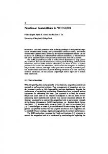
Fig. 5. Topology with several congested gateways 15 TCP flows are started from H1 to H2 and another 15 TCP flows from H2 to H1. Additionally a varying number of crosstraffic TCP flows is started from H3 to H4. The higher the number of cross-traffic TCP flows, the weaker the coupling between the forward and backward TCP flows between H1 and H2. Thus we can expect a decrease in the amplitude of the oscillation in case of an increase in the number of cross-traffic flows. There exist 4 output ports potentially subject to congestion. First, the output port from router1 to router2, displayed in the bottom left curve of subsequent figures. Second, the output port from router4 to router3, displayed in the upper left curve of subsequent figures. Third, the output port from router2 to router3, displayed in the bottom right curve of subsequent figures. Finally, the output port from router3 to router2, displayed in the upper right curve of subsequent figures. Default RED parameters for subsequent simulations: minth = 133, maxth = 533, B = 800, mean packet size = 500, 1/maxp = 79, wq = 0.00045. Deviations from the default parameter settings: Simulation no. cross TCPs maxp-1 r4-r3 maxp-1
r2-r3 maxp-1 r3-r2
4 1
5 5
6 20
7 100
67 10 110
85 10 90
105 7 50
125 2.5 20
400 200 0 50
100
150
200
250
0 0
300 queue-size queue router2forward - router3
0
instantaneous 400 average minth 200 maxth
50
100
150
200
250
400 200 0 0
50
100
150
200
250
instantaneous 400 average minth 200 maxth
0 0
300
50
100
time (sec.) time (sec)
150
200
250
400 200 0
300
600 router1 - router 2
600
600
0
300
queue-size backward queue router3 - router2
400 200 0 100
150
200
250
300
600 400 200 0 0
50
100
150
200
250
queue-size forward queue router2 - router3
queue-s ze backward queue router4 - router3 queue-s ze forward queue router1 - router2
600
0
600 400 200
100
150
200
250
300
150
200
250
300
instantaneous average minth maxth
0 0
300
50
100
time(sec) (sec.) time
time(sec) (sec.) time
400 200 0 0
50
100 150 200 250 300
600 400 200 0 0
50
100 150 200 250 300
time(sec) (sec.) time
queue-size queue router3backward - router2
800
600
800
queue-size queue router2forward - router3
queue-size queue router4backward - router3 queue-size queue router1forward - router2
Fig. 7. queue size over time; simulation 5 800
800
600 400 200
instantaneous average minth maxth
0 0
600 400 200
50
100
150
200
250
300
150
200
250
300
instantaneous average minth maxth
0 0
50
100
time (sec.) time (sec)
Fig. 8. queue size over time; simulation 6
250
300
400 200 0 0
50
100
150
200
250
300
800
600 400 200
instantaneous average minth maxth
0 0
600 400 200
50
100
150
200
250
300
150
200
250
300
instantaneous average minth maxth
0 0
50
100
time time (sec.) (sec)
Fig. 9. queue size over time; simulation 7
600 instantaneous average 400 minth maxth 200
50
200
800
time (sec) (sec.)
800
0
150
600
time(sec) (sec.) time
800
50
100
800
Fig. 6. queue size over time; simulation 4
0
50
queue-size queue router3backward - router2
router4 - router 3 600
600
800
queue-size queue router2forward - router3
queue-size backward queue router4 - router3
800
queue-size queue router1forward - router2
queue-size queue router1forward - router2
800
queue-size backward queue router3 - router2
queue-size queue router4backward - router3
800
As soon as the cross-TCP flows start creating traffic (20 seconds) on the link from router2 to router3, congestion is moved from the queue at router1 to the queue at router2. In the backward direction, traffic experiences a backlog at router 4. However, the higher the number of cross-traffic TCP flows, the higher the queue size at router3 due to an increased bandwidth consumption by acknowledgements of crosstraffic TCP flows. An increased queue size at router3 causes the queue at router4 to decrease. As expected, the higher the number of crosstraffic TCP flows, the looser the coupling between forward and backward TCP flows. Consequently, the number of cross-traffic TCP flows and the amplitude of oscillation are inversely proportional, as shown in figures 6-9. In general wide-area Internet scenarios, we may assume that forward and backward TCP flows are rather loosely coupled. However, in special environments like Intranets or LAN-to-LAN interconnection via Satellites, forward and backward TCP flows may be tightly coupled. No matter whether the oscillation persists or not for scenarios with loosely coupled forward and backward TCP flows, it is an eligible requirement on interacting control mechanisms to show desirable steady state convergence. This requirement is not fulfilled for the system RED and two-way TCP. Simulation 8 (figure 10) shows a transient state scenario with Web-like TCP traffic using the simulated network in figure 1. 6600 Web clients at hosts 1-3 perform a download, wait for an exponentially distributed think time and perform the next download. The think time has a mean of 90 seconds, the download-sizes are Pareto distributed according to the results on real Internet Web traffic presented in [12]. The mean number of active flows per direction equals 45 in this scenario. Other parameters: C 5
D 40
minth 42
maxth 168
B 252
wq 0.003
maxp-1 15
queue router2 - router1
200
host2
100
hub1
router2
router1
hub2
host5 host6
host3
50 0 290
queue router1 - router2
host4
host1
150
291
292
293
294
295
296
297
298
router3 10Mbps Ethernet 500kbps HDLC link
150 100
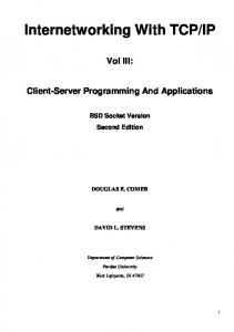
host7 Fig. 11. Measured network
50 0 290
291
292
293
294
295
296
297
298
time (sec.)
Fig. 10. RED queue with two-way Web-like TCP traffic Due to the short flow lifetimes and the high variance in the number of active flows, we cannot expect a strictly periodical oscillation like in the case of everlasting FTP flows. However, figure 10 illustrates clearly that the behavior of contrary queue size trajectories persists in case of Web-like TCP flows. Between 290 and 292, 293 and 294, 296 and 298 seconds of simulation time the first deviations of the average queue size curves in forward and backward direction have opposite signs. Other simulations with two-way Web traffic show that the amplitude and the periodicity of the oscillation depends on the per flow bandwidth RTT product, which is in turn a function of transfer length, think time, number of Web clients, bottleneck capacity and the RTT. The smaller the per flow bandwidth RTT product, the longer the duration of a transfer, the higher the amplitude and periodicity of the oscillation; assuming infinitely small per flow bandwidth RTT products, the per flow lifetimes would become infinite and the scenario with Web-like TCP traffic converges to the scenario with FTP traffic.
V. MEASUREMENTS WITH RED AND TCP TRAFFIC This section aims at investigating whether the simulation results obtained in previous sections can be applied to the real network situation.
A. Network Configuration Hardware: • hosts1-6: PC Pentium3, 350MHz, 128MB RAM • host7: PC Pentium MMX, 200MHz • hub1,2: Bay Networks 10/100 Mbps Ethernet Hub • router1: Cisco 3640, IOS 12.0 T • router2: Cisco 2611, IOS 12.0 T • router3: Cisco 2500, IOS 12.0 T
The propagation delay of all links can assumed to be equal zero (all equipment is located in one lab). The bottleneck capacity of 0.5Mbps is chosen sufficiently small to make the influence of collisions on the Ethernet links (hub1 to router1 and hub2 to router2) on the measurement results negligible.
B. One-way Delay Measurement of TCP Flows to obtain the instantaneous Queue Size Subsequent paragraphs show a configuration enabling measurement of the instantaneous queue size at the bottleneck link in figure 11 in arbitrary small time intervals without falsifying the measurement results by transmission of probe packets. A script running on host 7 schedules the start of TCP flows and collects results when the measurement is terminated. TCP bulk-data flows are created from host 1 to host 4, host 2 to host 5, host 4 to host 2 and host 5 to host 1. Host 3 and host 6 are time-synchronized by a GPS clock and run tcpdump. Two oneway delay measurements are performed: • One forward TCP flow from host 1 to host 4 is traced by two instances of tcpdump running on host 3 and host 6. • One backward TCP flow from host 4 to host 2 is traced by two instances of tcpdump running on host 6 and host 3. Tcpdump stores the time a packet is received and the TCP sequence number in a trace file. By relating the sequence numbers of the forward TCP flow in the trace files at host3 and host6 and subtracting the arrival time of a TCP segment at host 3 from the arrival time of the TCP segment at host 6 the oneway delay can be measured. This is equally valid for the TCP flow in backward direction. In order to avoid falsification of the delay measurements, lost and retransmitted packet have to be filtered out from the trace files. Knowing the one-way delay of packets, we can easily calculate the instantaneous queue size (in units of packets) at the RED gateway in order to create a queue size over time plot: queue size = ((delay - prop. delay) * link capacity) / MTU This configuration minimizes measurement errors as there is no traffic created during the execution of the measurement
except the flows to be measured. Additionally, tracing with tcpdump is completely separated from the task of traffic generation as it happens on different hosts.
C. Measurement with two-way TCP traffic
queue router1 forward- router2 (pkts) queue (pkts) queuebackward router2 - router1 queue
Several measurements with various parameter settings have been conducted. Due to space limitations, however, we are only able to show one measurement. Parameters: • forwarding delay in routers 2ms, propagation delay 0ms. All TCP flows start at the beginning of the measurement. The MTU size equals 512 bytes. • Traffic: 3 tcp flows host1 -> host4, host2 -> host5, host5 -> host1, host4 -> host2 (12 in total) • Red parameters: minth 7, maxth 40, buffersize 60, wq 0.015, maxp 1/10 60
40
20
0 60 65
70
75
70
75
80
85
90
95
100
80
85
90
95
100
40
20
0 65
time time(sec.) (secs)
Fig. 12. Instantaneous queue size at router 1 and router 2 Figure 12 shows that the queue size oscillates heavily from zero up to maxth. The oscillations at the two RED-gateways are phase-shifted by exactly 180 degree. As shown by figure 12, the measurement confirms the simulation results.
VI. CONCLUSIONS We examine the reasons for the existence of heavy oscillations with RED and two-way bulk-data TCP Reno traffic. These oscillations can be considered harmful as they cause sub-optimal link utilization (the instantaneous queue frequently equals zero) and discrimination between in-profile and out-of profile packets by RED based drop-preference mechanisms in Differentiated Services networks. We find that these oscillations are inevitable in case of tight coupling between forward and backward TCP traffic, caused by interactions of RED queue management and TCP Reno’s window-based congestion control algorithm, and persist for bulk-data TCP flows as well as Web-like TCP flows. The oscillations can be avoided if the queue management
algorithm enforces convergence to a certain buffer utilization. Additionally, the amplitude of the oscillation decreases in scenarios with loose coupling between forward and backward traffic (i.e. significant portion of cross traffic). However, even if loose coupling may be a common scenario in the Internet, it is an eligible requirement for interacting control mechanisms to show desirable behavior in simple, tightly coupled steady-state scenarios. This requirement is not fulfilled in the case of twoway TCP and RED, encouraging the development of new queue-management algorithms, avoiding oscillation in the presence of two-way TCP traffic.
VII. REFERENCES [1] S. Floyd, V. Jacobson, “Random Early Detection Gateways for Congestion Avoidance”, IEEE/ACM Transactions on Networking, August 1993 [2] B. Braden, D. Clark et al., “Recommendations on Queue Management and Congestion Avoidance in the Internet”, RFC 2309, April 1998 [3] V. Firoiu, M. Borden, “A Study of active Queue Management COngestion Control”, IEEE Infocom 2000 [4] T. Ziegler, “Fairness and Efficiency of Internet Congestion Control”, PhD Thesis, May 2000; www.newmedia.at/ ~tziegler/papers.html [5] S. Floyd, K. Fall, K. Tieu, “Estimating arrival rates from the RED packet drop history”, March 1998, unpublished, http://www.aciri.org/floyd/end2end-paper.html [6] K.K. Ramakrishnan, S. Floyd, "A Proposal to add Explicit Congestion Notification (ECN) to IP", RFC2491, January 1999, http://www.aciri.org/floyd/ecn.html [7] S. Floyd, “TCP and Explicit Congestion Notification”, Computer Communication Review, V.24. N.5, October 1994, p. 10-23 [8] Cisco Web-pages, http://www.cisco.com/warp/public/ 732/netflow/qos_ds.html [9] D. Clark, “Explicit Allocation of Best Effort Packet Delivery Service”, http://www.ietf.org/html.charters/diffservcharter.html [10] NS Simulator Homepage, http://www-mash.cs.berkeley.edu/ns/ [11] W.R. Stevens, “TCP/IP illustrated”, Vol. 1, Addison Wesley 1994 [12] B. Mah. ‘‘An Empirical Model of HTTP Network Traffic’’, Proceedings of INFOCOM ’97, Kobe, Japan, April 1997