locked onto a suitable fringe of this stable cavity, achieving a very small long term drift and ..... perature of about 20 K above ambient room temperature.
Stabilization and precise calibration of a continuous-wave difference frequency spectrometer by use of a simple transfer cavity E. Riedle,a)Sb)S. H. Ashworth,b) J. T. Farrell, Jr., and D. J. Nesbittc) Joint Institute for Laboratory Astrophysics, University oj. CoIorado and National Institute of Standards and Technology, Boulder, Coiorado 80309-0440
(Received 15 July 1993; acceptedfor publication 24 September 1993) A novel, simple, and inexpensivecalibration schemefor a continuous-wavedifferencefrequency spectrometeris presented,basedon the stabilization of an open transfer cavity, by locking onto the output of a polarization stabilized HeNe laser. High frequency, acoustic fluctuations of the transfer cavity length are compensatedwith a piezoelectric transducer mounted mirror, while long term drift in cavity length is controlled by thermal feedback.A single mode Ar+ laser, used with a single mode ring dye laser in the differencefrequency generationof 2-4 pm light, is then locked onto a suitable fringe of this stable cavity, achieving a very small long term drift and furthermore reducing the free running Ar + linewidth to about 1 MHz. The dye laser scan provides tunability in the difference frequency mixing process, and is calibrated by marker fringes with the same stable cavity. Due to the absolute stability of the marker cavity, precise frequency determination of near infrared molecular transitions is achieved via interpolation betweenthesemarker fringes. It is shown theoretically that the residual error of this schemedue to the dispersion of air in the transfer cavity is quite small, and experimentally that a frequency precision on the order of 1 MHz per hour is routinely obtained with respect to molecular transitions.
1. INTRODUCTION
Over the past decade, continuous-wave (cw) laser spectrometerswith MHz levels of spectral resolution have beendevelopedover the near ultraviolet (UV),lm3 all of the visible4,’and large regions of the infrared.&* In these subDoppler molecular spectrometersfull spectroscopicuse of the extremely high resolution can only be made if a suitable calibration scheme is implemented. Since the scanning of the spectrum typically takes hours, excellent long term stability of the system is necessary. One way to obtain the proper calibration is by comparison to a precisely known referencespectrum. However, such spectraare often not availablein all regions of interest and can be difficult to record simultaneously. A second way to obtain precise spectral information for various molecular lines is by direct measurementof the wavelength or frequency in a wavemeter (traveling Michelson interferometer). It has been shown’ that this is possible with an absolute precision of better than 1 MHz but for most systems this is prohibitively time consuming. The most frequently used calibration method is therefore by interpolating the molecular spectrum with the transmission spectrum of a suitable Fabry-Perot cavity. No absolute calibration is normally attained in this way, but for most applications, a relative calibration is easily obtained and quite sufficient. On the other hand, the absoa)1991-92 JILA Visiting Fellow. “Present address: Max-Born-Institut fdr Nichtlineare Optik und Kurzzeitspektroskopie, Rudower Chaussee 6, D-12489 Berlin, Germany. ‘&tat?? Member, Quantum Physics Division, National Institute of Standards and Technology. 42
Rev. Sci. Instrum.
65 (l), January
1994
lute accuracy can be quite high if it is possible to keep the optical spacing of the mirrors constant. This is typically done by using a low thermal expansionspacerlike Zerodur ceramic and high quality temperature control.“*” In addition the cavity has to be evacuatedto avoid any drift of the transmission fringes due to change in the refractive index in the cavity causedby ambient pressure changes. The interest in a calibration precision on the order of 1 MHz/h is quite keen and no commercial systems are readily available. We therefore have set out to design and build a simple system for use with our differencefrequency spectrometer that can perform to this level of accuracy. Instead of the more conventional reliance on the long term thermal stability of a Zerodur material, we have opted to lock an open cavity actively to a polarization stabilized HeNe laser and use this as a transfer cavity for the frequency stabilization of the Arf laser used in conjunction with a single mode dye laser to generatethe infrared (IR) light. In addition, this cavity is used to record marker fringes from the scanning of the dye laser, which therefore provides accurate frequency markers in the infrared. The design of the system will be described in detail below and the magnitude of possible drifts due to dispersion of air discussed. Finally, the successful performance of the instrument is demonstratedby recording a known molecular spectrum repeatedly over many hours and comparing the successivefrequency measurements. II. DESIGN A. Basic
OF THE SYSTEM considerations
The conventional approach to the construction of a highly stable calibration setup for optical spectrometersis
OQ34-6746/94/65(1)/42/7/$6.00
@ 1994 American
Institute
of Physics
Downloaded 27 Aug 2008 to 129.187.254.47. Redistribution subject to AIP license or copyright; see http://rsi.aip.org/rsi/copyright.jsp
the use of a suitable Fabry-Perot interferometer (FPI). A fixed frequency laser can either be locked to one of the cavity modes of the FPI or it can be used for calibration of a tunable laser scan. To reduce the influence of ambient temperature and pressurechanges,a spacer for the mirrors with very low expansion coefficient is preferred and the whole optical cavity is typically placed in a sealedtank. “J ’ The tank is often evacuated and needs to be kept at as constant a temperature as possible. To understand the necessarydemands on the stability of the temperature of such a system and the tolerable pressure changes,we start from the well known condition for the frequency Y of a given longitudinal mode of a confocal FPI Nco v=c-j 9
(1)
where n is the index at temperature To. As an example, for the HeNe laser at atmospheric pressure this already amounts to a Sv/ST of 455 MHz/K. Hence at ambient pressure, even small temperature changeswould causesignificant drift. Again, keeping the FPI in an evacuatedtank can eliminate this density related dependenceof the mode frequency on the temperature. The more commonly treated temperature influence on the frequency of a given FPI cavity mode is the thermal expansion of the spacer used to separatethe mirrors. For a thermal expansion coefficient CYof the spacer this influence can be seen to be
v+sv= 4nd( 1Nco +aST)
$
4nd
or Svz -aSTv.
with d the spacing between the mirrors, co the speed of light in vacuum, it the refractive index of the medium between the mirrors, and N the integral mode number. F& the 632.8 nm (4.7361 X lOI Hz) output wavelength of a HeNe laser, the refractive index of air under standard conditions of 760 Torr ( 1 Torr= 133 Pa) pressurep. and 288 K temperature To is approximately it= 1+2.7652X 10m4, where the quantity (it - 1) is linearly proportional to the density of the gas medium.12 A change Sp in pressure at constant temperature will lead to a changeof the density of the air in the cavity, and consequently to a new frequency V+SV of the desired mode given by
Nco v+Sv=4[n+(n-l)(Sp/‘po)]d~4nd
From Eqs. ( 1) and (2) it follows that svz---
n-l
Sp
n
PO
vz--(n--l)
Ev,
(3)
which the HeNe laser frequency at near ambient pressures amounts to a Sv/Sp of - 172 MHz/Torr. Therefore, the pressureof the air betweenthe mirrors has to be controlled to better than 0.01 Torr if a stability of the FPI on the order of 1 MHz is to be achieved. Hence, the FPI is typically placed inside a vacuum tank, though this is explicitly not the choice made for the transfer cavity design presented herein. The influence of a temperature change on an open cavity is twofold. On the one hand, it will change the density of the air in the FPI and influence the frequency of the cavity mode in a similar fashion to a pressure change, and on the other hand the physical spacing of the mirrors will be changedby thermal expansionof the spacer.The former effect will be considered first. At constant pressure, a temperature change ST leads to a density change of the air betweenthe mirrors which in turn leads to a frequency change of the cavity mode of (4)
(1 -aST),
(6)
For Zerodur ceramic (Y= -0.3~ 10m7/K and Sv/ST=14 MHz/K, while for fused silica a=5.5 X 10-‘/K and Sv/ ST=260 MHz/K. This means that even for extremely low expansion Zerodur as a spacer, the absolute temperature of the FPI must be controlled to better than 0.1 K to ensure a frequency stability on the order of 1 MHz. B. The FPI as a transfer
cavity
The reasonsdiscussedabove commonly lead to the use of an actively temperature controlled FPI with a low expansion spacer placed in a vacuum tank if high precision calibration of optical spectra is needed. However, such a system is fairly complicated to build and not very convenient to align. The alternative we consider is an open cavity (at ambient pressure) which is not passively stabilized but instead, locked to a simple reference laser with a highly stable output frequency. Such a reference laser is indeed readily available in the polarization stabilized HeNe laser.i3 What remains to be investigated is the locking scheme and how well such a transfer cavity system performs over ranges of wavelengths (frequencies) both close and far from the HeNe laser output. The system we have devised both (i) to stabilize the frequency of the ArS laser and (ii) to calibrate the scan of the dye laser used for the near IR cw difference frequency generation in our spectrometer7is shown schematically in Fig. 1. In the interest of simplicity, only the optical components are depicted. The heart of the system is a 30 cm length confocal FPI with very broadband mirrors ( T= 6 =t 2% for 400-780 nm) . The measured finesseof this cavity is 20, i.e., it has a fringe width of 13 MHz at the 250 MHz free spectral range (FSR). The cavity is locked onto the frequency of a polarization stabilized HeNe laser whose absolute frequency stability is measured to be on the order of 0.1 MHz/h by optical mode beating against an iodine stabilized HeNe laser. Slow control of the cavity length is performed by heating the middle section of the confocal mirror spacer, while fast control is obtained using a piezoelectric transducer (PZT)-supported end mirror. The Arf laser fre-
Rev. Sci. Instrum., Vol. 65, No. 1, January 1994 Difference frequency spectrometer 43 Downloaded 27 Aug 2008 to 129.187.254.47. Redistribution subject to AIP license or copyright; see http://rsi.aip.org/rsi/copyright.jsp
,Dye
He Ne Detector /;\
Laser
I .
Single Frequency Argon Ion Laser
IF2 Stabilised HaNa 1~ser
Detector
IrJ b
Dye Laser Detector
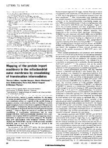
PIG. 1. Schematic diagram of the optical setup used for stabilization of a difference frequency spectrometer. The transfer cavity (FPI) is locked onto a polarization stabilized HeNe laser. The single frequency Ar + laser, in turn, is locked to the cavity. Finally the scan of the dye laser is calibrated by recording the transmission fringes of the stabilized transfer cavity. A number of mirrors (M) are used to steer the beams, interference filters (IF) and polarizing beamsplitters are employed to combine the various laser beams collinearly or separate them after passing through the cavity. Two planoconvex lenses (Ll and L2) with f=500 m m are used to compensate for the refractive power of the cavity mirrors. All three beams are monitored on separate detectors. A beamsplitter (BS) is used to select the required amount of’dye laser and Ar+ laser radiation out of the main beam going to the experiment.
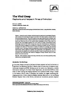
quencyis then locked to a suitablecavity m o d eof the FPI, F inally, the transmissionpattern of the FPI is recordedfor calibration as the dye laser is scanned.All three laser beams are suitably attenuated and combined collinearly with a polarizing beamsplitter and/or interferencefilter beforethey are coupledinto the transfer cavity. The transm itted light is similarly split into its three componentsand eachcolor detectedon a separatedetector. The design of the FPI is shown in somewhat more detail in F ig. 2. Starting from the right, the spacerconsists of a lZcm-long section of 2.5-cm-diamPyrex tubing, two stainlesssteel-to-Pyrexgraded sealswelded together with their stainlesssteel sides, a second 8-cm-long section of Pyrex, and finally a 2.5-cm-long tubular piezoceramic transducer(PZT). Most of the stainlesssteel part of the spaceris wrappedwith heatingtape to allow active control of the cavity length. The numerical examplegiven in the precedingsection (HeNe laser frequency) shows that a 1 Torr increasein Fabry-Perot
Interferometer
Detector
I - . .._ml IL I’
Proportional * = 0.003s Propoltlonat r P IS
FIG. 2. Schematic diagram of the electronic locking scheme used to stabilize the transfer cavity onto the stabilized HeNe laser. See text for details. 44
Rev. Sci. Instrum., Vol. 65, No. 1, January 1994
pressure(at constanttemperature)of the air in the cavity would lead to a frequencyshift of the cavity m o d eof - 172 MHz. If the whole length of the spacerwere heatedfor thermal control of the cavity length and fused silica used for a spacer,a drop by 0.7 K would compensatefor this pressurechange.However, heatingthe whole length is not very practical, insteadonly a fifth can typically be heated. For a fused silica cavity, the temperatureof this shorter section must now be changedby 3.5 K. For a small pressurechangethis scalingm ight just be acceptable,for larger variations it turns out to be prohibitive. Hence we have chosena 6-cm-longstainlesssteelsectionas the heatedpart of the spacer,i.e., a material with a much higher thermal expansioncoefficient (a = 187X lo-’ K), and for which a drop in temperatureof only 0.1 K sufficesto compensate for the 1 Torr pressurerise. This allows accessto a wide dynamiclocking rangewith only a moderateinitial heating (about 20 K above room temperature). In addition, the effect of heatingthe air inside the spacer[e.g., seeEq.(4)] is m inimized. Oncethe stainlesssteelpart of the spacerhas beenchosenfor the describedreasons,Pyrex glasswith a five-fold smaller expansioncoeflicienta =32 x 10m7/K is a natural and convenientchoicefor the remainingsectionsof the spacer.In particular, gradedsealsof stainlesssteeland Pyrex are readily availableand the five-fold ratio between the two expansioncoefficientscan nearly perfectly compensatefor the five-fold ratio in sectionlengths. A 1 K change in temperatureof the Pyrex (e;g., by a changein the lab temperature) can therefore be compensatedby an equal but opposite changeof the temperature of the stainless steel.Theseopposingeffectshelp m inimize the influenceof a m b ient temperaturechangeson the averagetemperature of the air insidethe FPI and the associatedfrequencyshifts from changesin air density.
C. Possible
limitations
of performance
The systemdescribedin the precedingsectiontransfers the stability of the referenceHeNe laser to both the Ar+ laser and the dye laser fringes through the use of an open transfer cavity. For this purpose,the length of the cavity is controlled so as to compensatefor any changesin a m b ient pressureand temperature.However, the associatedshift in frequency of any cavity m o d e dependson the refractive index of the m e d ium betweenthe m irrors at the correspondingwavelength.Sincethe refractive index of airdependsupon wavelength,there will still be a small residual error in the system due to this dispersionthat eventually lim its the performanceof the system. This section addressesat what level of precision this will happen.For simplicity, we consideronly the pressuredependence(at constanttemperature)but by comparisonof Pqs. (3) and (4), the temperaturedependence can be obtainedby simple scaling. To lock a cavity m o d eof the FPI (with m o d enumber N ueNe)to the frequency (vm.& of the stabilized HeNe laser at a m b ientpressure(p), the length (d) of the confocal cavity has to be Difference frequency spectrometer
Downloaded 27 Aug 2008 to 129.187.254.47. Redistribution subject to AIP license or copyright; see http://rsi.aip.org/rsi/copyright.jsp
‘1
N HeN&O d=------4vHeNe
1-t
( n~eNe -
1) (p/PO)
NHeN&O N- 4vHeNe
(7)
To compensate for a change Sp in pressure, the mirror spacing must be adjusted to d+6d, where ad
1
-NHeN&O
sp=
bHcNc--
4vHeNe
l)
(8)
p;
or Sdz --d(nH,N,-1)
’ PO :
In Eq. (9) the refractive index was set equal to 1 since we consider only linear terms in Sd, i.e., first order changesin the cavity length. A second mode of the transfer cavity (the mode number N1,,,) with a frequency close to either the Ar+ laser or the dye laser will, by analogy with Eq. (7)) have a frequency vlaserat the initial pressure of %S,P
--
4d
With the pressure changed by Sp and the accompanying change in length 6d to keep the cavity locked to the HeNe, the frequency for the mode will be changed by Sy,,,, according to
(11) Substituting Eq. (9) and taking only linear terms in the changesand rearranging, one finally obtains %se~o 6~ - (nHeNc-nlaser) 4d PO
Equation ( 12) shows that the residual error from the dispersion of the refractive index of air is proportional to the difference betweenthe refractive index at the wavelength of the HeNe laser to which the cavity is locked and that of the second laser. Hence, the closer the two wavelengthscan be chosen, the lower the residual error from the use of an open transfer cavity will be. In our experiment the cavity is locked to the 632.8 nm line of the HeNe, and 3963 cm-’ IR light is generated by difference frequency mixing the 488.0 nm Ar+ line (20486 cm-‘) and the output of the dye laser in the 605 nm region. The refractive index of air (under standard temperature and pressure conditions) at these two wavelengths is 1+2.7929 X 10m4 and 1+2.7690x 10m4, respectively.l2 With nHeNe=1+2.7652X low4 this results in residual errors of Sv&Sp= -0.25 MHz/Torr and Sv,/Sp= -2.24 MHz/Torr. For the resulting IR light, the drift is only - 1.99 MHz/Torr. One can seethat, for the small pressure Rev. Sci. Instrum.,
Vol. 65, No. 1, January
111.IMPLEMENTATION
In this section we explain in more detail how the cavity is actually locked to the stabilized HeNe laser and the Ar+ laser in turn to the cavity. The recording of the transmission fringes with scanning of the dye laser is standard and will not be detailed. A. Locking
(
~V*ase~~-
changesencounteredin a typical laboratory environment, a stability on the order