Stabilization and Synchronization of Memristive Chaotic Circuits by ...
Recommend Documents
ally coupled systems. First, the achronal synchronization of two mutually chaotic circuits, which are ... community of chaotic oscillators. Here we depart from two ...
used to implement a two-dimensional 33 grid scroll chaotic attractor. The implementation of complex dynamics with low cost circuits is very appealing; moreover, ...
Circuits with Applications to Communications. Kevin M. Cuomo, Member, IEEE,
Alan V. Oppenheim, Fellow, IEEE, and Steven H. Strogatz. Abstract— A circuit ...
system is described. The chaotic behavior of the circuit closely matches the results predicted by numerical experiments. Using the concept of synchronized ...
Index TermsâChaotic synchronization, Chua's circuit, dynamic arrays, pattern forming ...... sine-Gordon equation,â Physica D, vol. 97, pp. 429â470, 1996.
studied the kneading theory analysis of the Duffing equation [3] and the symbolic dynamics and chaotic synchronization in coupled Duffing oscillators [2] and [4].
Jul 11, 2013 - chronization of chaotic oscillators. We derive analytical ... interacting systems. In contrast, we assume a situation where one oscillator sends.
software techniques were used for data encoding. However, the .... For zero external drive M to the XOR gate the circuit exhibits damped oscillations. For all reasonable (x2 ... simple technique of recovering the signal M(t) at the receiver end.
Polyurethanes comprise a kind of materials that can vary from rubbery to glassy thermoplastics from linear polymers to thermoset. This versatility can be further.
[3] F.J. Fahy & S.N.Y. Gerges, Intensidade Sonora;. Seminário International, São Paulo - 18 e 19 de Abril. (1994). [4] F. Jacobsen, Field indicators: useful tools, ...
We propose a general formulation of coupling for engineering synchronization in chaotic oscillators for unidirectional as well as bidirectional mode.
chaotic envelope at the transmitter end, and send it through the channel as a chaotic signal. At the receiver end, a chaotic oscillator whose parameters are ...
3173 (Springer-. Verlag, Berlin, Heidelberg, NY), pp. 144â149. Zhou, J., Chen, T. & Xiang, L. [2005a] âAdaptive syn- chronization of delayed neural networks ...
engineering communities. Gyroscopes, from a purely scientific viewpoint, show many strange and interesting properties, and from an engineering viewpoint, ...
Sep 3, 1992 - ing" the device up, over half a dozen cycles, using roughly one-sixth the ...... Figure 2.3: Top-level block diagram of Perfect Moment: reference ... of the cells that they touch, together with time of entry to and exit ...... Trajector
the Barbalat's lemma, limt!1 emÑtЮ ! 0. Considering the adaptation laws of (13) and (27), since limt!1 emÑtЮ ! 0 and x, u 2 l1, it is clear that Ëвi, Ëbi ! 0 as t ! 1.
In this paper, coupling properties of regular and chaotic calcium oscillations are examined. Synchronized .... proper insulin secretion relies on synchronized os-.
Jul 6, 2015 - to the interval [Ron, Roff ] (note that Ron < Roff ). Numerical Results. ..... Stewart, and R. S. Williams, Nature 464, 873 (2010). 14 Y. V. Pershin ...
Eng SA 1, 95-116 (1969). ... Hen. , 1-101 (1983). 143 (1977). o ows A.; Truper, H. G.; Dworkin, M.;. Hoe. Hua ... ng, A.A., âKinetics studies on insoluble cellulose-.
Abstractââ Copper recoveries using two methodologies of acid leaching of a low-grade ore are reported in this work. The ore, abounding in oxidized species, ...
Jun 9, 2017 - the memristor, R(w) = Ron(1 â w) + Roff w is the resis- tance and I and S ..... [22] J. J. Yang, D. B. Strukov, D. R. Stewart, Nature Nano. 8 (2013).
Nov 2, 2016 - represents the polarity of the memristor, Ron the limit- ... Roff /Ron, typically r â« 1. ..... [4] J. J. Yang, D. B. Strukov, D. R. Stewart, Memristive.
secure data transmission and so on. .... big challenge to secure communication by means of chaos. .... the signal recovery error Ës = s â Ës converges to the.
Stabilization and Synchronization of Memristive Chaotic Circuits by ...
Nov 6, 2017 - circuits shown by Muthuswamy [22]. In many practical appli- .... Figure 1: The state trajectory of the memristor based chaotic circuit shown in (1).
Hindawi Complexity Volume 2017, Article ID 5186714, 10 pages https://doi.org/10.1155/2017/5186714
Research Article Stabilization and Synchronization of Memristive Chaotic Circuits by Impulsive Control Limin Zou,1 Yang Peng,2 Yuming Feng,3 and Zhengwen Tu3 1
School of Mathematics and Statistics, Chongqing Technology and Business University, Chongqing 400067, China School of Mathematics and Statistics, Chongqing Three Gorges University, Chongqing 404100, China 3 Key Laboratory of Intelligent Information Processing and Control, Chongqing Three Gorges University, Chongqing 404100, China 2
1. Introduction The memristor was postulated as the fourth circuit element by Chua [1, 2] and was realized by HP Labs [2, 3]. Memristor has widely potential applications in electronic circuits, computer memory, reconfigurable computing, and so on [4–7]. Recently, implementation of memristor based chaotic circuits is an active topic of research. For example, some memristor based chaotic circuits were proposed by Itoh and Chua [8] and Muthuswamy and Kokate [9]. Memristor based chaotic circuits have applications in many fields; for example, a memristor based chaotic circuit for image encryption was proposed by Lin and Wang [10]. In practical applications, impulsive control has some advantages: for example, impulsive control provides an efficient way in dealing with systems especially which cannot endure continuous control inputs. During the last several decades, impulsive control theory has attracted considerable attention because impulsive control method can be employed in many fields, such as the stabilization and synchronization of chaotic systems [11–14] and complex dynamical networks [15–19]. For more results on impulsive control and its
applications, the reader is referred to [11, 20, 21] and the references therein. Recently, complex dynamical systems are receiving much attention, and there is no exception for chaotic systems. Muthuswamy [22] provided a practical implementation of a memristor based chaotic circuit. By applying impulsive control theory, Yang et al. [23] obtained some sufficient conditions for the asymptotic stabilization and synchronization of the memristor based chaotic system shown in [22]. In this note, we shall also consider the asymptotic stabilization and synchronization of memristor based chaotic circuits, as in [22]. We first derive a less conservative sufficient condition for the stability of the memristor based chaotic circuits shown by Muthuswamy [22]. In many practical applications, we cannot guarantee the systems without any error due to the limit of equipment and technology. For this reason, we discuss the effect of errors on stability in this note. Meanwhile, we also discuss impulsive synchronization of two memristor based chaotic systems. Compared with the results shown in [23], our methods are more general and more applicable. Finally, we give some numerical examples which show the effectiveness of our methods.
2
Complexity 𝑥3 = 𝑖𝐿 ,
2. Memristor Based Chaotic Circuit and Its Equivalent Form
𝑥4 = 𝜙,
The equations for the memristor based chaotic circuit presented in [22] are described by
𝑎1 =
1 , 𝐶1
𝑑V1 (𝑡) 1 V2 (𝑡) − V1 (𝑡) ( = − 𝑖 (𝑡)) , 𝑑𝑡 𝐶1 𝑅
𝑎2 =
1 , 𝐶2
𝑑V2 (𝑡) 1 V1 (𝑡) − V2 (𝑡) ( = − 𝑖𝐿 (𝑡)) , 𝑑𝑡 𝐶2 𝑅
𝑎3 =
1 , 𝑅
𝑎4 =
1 . 𝐿
𝑑𝑖𝐿 (𝑡) V2 (𝑡) = , 𝑑𝑡 𝐿
(1)
(6)
𝑑𝜙 (𝑡) = V1 (𝑡) , 𝑑𝑡
Then the memristor based chaotic circuit (1) can be rewritten as
where 𝑖 (𝑡) = 𝑊 (𝜙 (𝑡)) V1 (𝑡) =
𝑑𝑞 V (𝑡) . 𝑑𝜙 1
𝑑𝑥1 = 𝑎1 (𝑎3 (𝑥2 − 𝑥1 ) − 𝑊 (𝑥4 ) 𝑥1 ) , 𝑑𝑡 (2)
𝑑𝑥2 = 𝑎2 (𝑎3 (𝑥1 − 𝑥2 ) − 𝑥3 ) , 𝑑𝑡
The author of [22] chose a cubic nonlinearity for the 𝑞-𝜙 function: 𝑞 (𝜙) = 𝛼𝜙 + 𝛽𝜙3
𝑊 (𝜙) =
𝑑𝑞 = 𝛼 + 3𝛽𝜙2 . 𝑑𝜙
𝑑𝑥4 = 𝑥1 , 𝑑𝑡
(3)
and so the memductance function 𝑊(𝜙) is given by
which is equivalent to 𝑑𝑥1 = 𝑎1 (𝑎3 (𝑥2 − 𝑥1 ) − 𝛼𝑥1 − 3𝛽𝑥1 𝑥42 ) , 𝑑𝑡
(4)
𝑑𝑥2 = 𝑎2 (𝑎3 (𝑥1 − 𝑥2 ) − 𝑥3 ) , 𝑑𝑡
We choose the system parameters as
𝑑𝑥4 = 𝑥1 . 𝑑𝑡
𝛽 = 0.004 ⋅ 10−3 ,
𝐿 = 15.8 H,
(8)
𝑑𝑥3 = 𝑎4 𝑥2 , 𝑑𝑡
𝛼 = −0.663 ⋅ 10−3 ,
𝑅 = 2 kΩ,
(7)
𝑑𝑥3 = 𝑎4 𝑥2 , 𝑑𝑡
(5)
By decomposing the linear and nonlinear parts of the memristor based chaotic circuit system in (8), we can rewrite it as
𝐶1 = 6.1 𝜇F,
𝑋̇ = 𝐴𝑋 + 𝜓 (𝑋) ,
𝐶2 = 71 𝜇F,
(9)
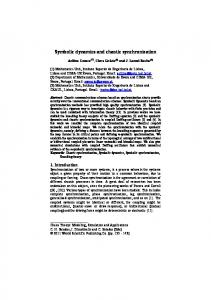
where which make system (1) chaotic [22, 23]. Figure 1 shows the chaotic phenomenon of this system with the initial condition (V1 (0), V2 (0), 𝑖𝐿 (0), 𝜙(0))𝑇 = (0.1302, 0.0924, 0.0078, 0.1253)𝑇 . In the sequel, we mainly adopt the notation and terminology in [23]. To analyze the asymptotic stabilization of system (1), we let
Figure 1: The state trajectory of the memristor based chaotic circuit shown in (1).
The impulsively controlled memristor based chaotic circuit is given by 𝑋̇ = 𝐴𝑋 + 𝜓 (𝑋) , Δ𝑋 = 𝐵𝑋,
𝑡 ≠ 𝜏𝑘 ,
𝑡 = 𝜏𝑘 , 𝑘 = 1, 2, . . . ,
𝑉 (𝑡, 𝑋) = 𝑋𝑇 𝑋.
(13)
(11)
where 𝜏𝑘 denote the moments when impulsive control occurs and 𝐵 ∈ 𝑅𝑛×𝑛 is impulsive control gain. Without loss of generality, we assume that 𝑡0 < 𝜏1 < 𝜏2 < ⋅ ⋅ ⋅ , lim𝑘→∞ 𝜏𝑘 = ∞.
3. Impulsive Control of the Memristor Based Chaotic Circuit Shown by Muthuswamy In this section, we design impulsive control for the memristor based chaotic circuit shown by Muthuswamy. Theorem 1. Let 𝜆 1 be the largest eigenvalue of (𝐼 + 𝐵)𝑇 (𝐼 + 𝐵) and suppose that 𝜆 2 is the largest eigenvalues of 𝐴 + 𝐴𝑇 . Then the origin of impulsive control system (11) is asymptotically stable if 𝜆 2 (𝜏𝑘+1 − 𝜏𝑘 ) ≤ −ln (𝛾𝜆 1 ) , 𝛾 > 1.
Proof. Let us construct the following Lyapunov function:
(12)
It is easy to verify that conditions 1 and 4 of Theorem 3.1.3 in [11] are satisfied. When 𝑡 ≠ 𝜏𝑘 , we have 𝐷+ 𝑉 (𝑡, 𝑋) = 𝑋𝑇 (𝐴 + 𝐴𝑇 ) 𝑋 + 2𝑋𝑇 𝜓 (𝑋) = 𝑋𝑇 (𝐴 + 𝐴𝑇 ) 𝑋 − 6𝑎1 𝛽𝑥12 𝑥42
(14)
≤ 𝑋𝑇 (𝐴 + 𝐴𝑇 ) 𝑋 ≤ 𝜆 2 𝑋𝑇 𝑋. Hence, condition 2 of Theorem 3.1.3 in [11] is satisfied with 𝑔 (𝑡, 𝜔) = (𝜆 2 − 2𝑎1 𝛼) 𝜔.
(15)
From the fact that ‖𝑋 + 𝑈 (𝑘, 𝑋)‖ = ‖𝑋 + 𝐵𝑋‖ ≤ ‖𝐼 + 𝐵‖ ‖𝑋‖
(16)
4
Complexity
and ‖𝐼 + 𝐵‖ is finite, we know that there exists a 𝜌0 > 0 such that 𝑋 ∈ 𝑆𝜌0 , which implies that 𝑋 + 𝑈(𝑘, 𝑋) ∈ 𝑆𝜌 for all 𝑘. When 𝑡 = 𝜏𝑘 , we have 𝐷+ 𝑉 (𝜏𝑘 , 𝑋 + 𝐵𝑋) = (𝑋 + 𝐵𝑋)𝑇 (𝑋 + 𝐵𝑋) = 𝑋𝑇 (𝐼 + 𝐵)𝑇 (𝐼 + 𝐵) 𝑋
(17)
≤ 𝜆 1 𝑋𝑇 𝑋. Hence, condition 3 of Theorem 3.1.3 in [11] is satisfied with 𝜒𝑘 (𝜔) = 𝜆 1 𝜔.
(18)
It follows from Theorem 3.1.3 in [11] that the asymptotic stability of the impulsive control system (11) is implied by that of the following comparison system: 𝜔̇ (𝑡) = (𝜆 2 − 2𝑎1 𝛼) 𝜔, 𝑡 ≠ 𝜏𝑘 , 𝜔 (𝜏𝑘+ ) = 𝜆 1 𝜔 (𝜏𝑘 ) ,
(19)
𝜔 (𝜏0+ ) = 𝜔0 ≥ 0. It follows from Theorem 3.1.4 in [11] that if (𝜆 2 − 2𝑎1 𝛼) (𝜏𝑘+1 − 𝜏𝑘 ) ≤ − ln (𝛾𝜆 1 ) ,
𝛾 > 1,
(20)
is satisfied, then the origin of (11) is asymptotically stable. This completes the proof.
our result is less conservative than Theorem 1 of [23]. Meanwhile, our method is also simpler than Theorem 1 of [23], because we do not need to calculate the supremum of |𝑊(𝑥4 )|. In many practical applications, we cannot guarantee the impulses without any error due to the limit of equipment and technology. So we should take into account the influence of impulsive control gain errors on the systems. Motivated by the above discussions, we will study the stabilization of system (11) with bounded impulsive control gain error. The corresponding system can be described as 𝑋̇ = 𝐴𝑋 + 𝜓 (𝑋) ,
Δ𝑋 = (𝐵 + Δ𝐵) 𝑋, 𝑡 = 𝜏𝑘 , 𝑘 = 1, 2, . . . ,
0
Theorem 3. Let 𝜆 1 be the largest eigenvalue of 1 (1 + 𝜀) (𝐼 + 𝐵 + 𝐵𝑇 ) + (1 + 𝜀 + 𝑚2 (1 + )) 𝐵𝑇 𝐵, 𝜀
̃ is the largest eigenvalues of 𝐴 ̃+ 𝐴 ̃𝑇 . and suppose that 𝜆 2 Yang et al. showed in [23] that the origin of impulsive control system (11) is asymptotically stable if 2√sup {𝑎12 𝑊2
(25)
where 𝜀 > 0 and suppose that 𝜆 2 is the largest eigenvalues of 𝐴 + 𝐴𝑇 . Then the origin of impulsive control system (24) is asymptotically stable if
𝑉 (𝑡, 𝑋) = 𝑋𝑇 𝑋.
0
(24)
where Δ𝐵 is gain error, which is often time-varying and bounded. As pointed out in [21, 24], we can assume that Δ𝐵 = 𝑚𝐹(𝑡)𝐵, 𝑚 ≥ 0, and 𝐹𝑇 (𝑡)𝐹(𝑡) ≤ 𝐼.
Remark 2. Let −𝑎1 𝑎3 𝑎1 𝑎3
𝑡 ≠ 𝜏𝑘 ,
(23)
where 𝐶 = 𝐼 + 𝐵. The rest of proof is the same as that of Theorem 1, so we omit it here for simplicity. This completes the proof. In many practical applications, the parameters 𝑎1 = 1/𝐶1 , 𝑎2 = 1/𝐶2 , 𝑎3 = 1/𝑅, and 𝑎4 = 1/𝐿 may also contain errors. In what follows, we will consider system (24) with parameter uncertainty. The corresponding system can be described as 𝑋̇ = (𝐴 + Δ𝐴) 𝑋 + 𝜓 (𝑋) , 𝑡 ≠ 𝜏𝑘 , Δ𝑋 = (𝐵 + Δ𝐵) 𝑋, 𝑡 = 𝜏𝑘 , 𝑘 = 1, 2, . . . ,
(29)
Complexity
5
where Δ𝐴 is the parametric uncertainty and has the following form: Δ𝐴 = 𝜇𝐺(𝑡)𝐴, 𝐺(𝑡)𝐺𝑇 (𝑡) ≤ 𝐼, 𝜇 ≥ 0. Theorem 4. Let 𝜆 1 be the largest eigenvalue of 1 (1 + 𝜀) (𝐼 + 𝐵 + 𝐵 ) + (1 + 𝜀 + 𝑚 (1 + )) 𝐵𝑇 𝐵, 𝜀 𝑇
2
(30)
where 𝜀 > 0 and suppose that 𝜆 2 is the largest eigenvalues of (𝐴 + 𝐴𝑇 ) + 𝜇(𝐴𝑇 𝐴 + 𝐼). Then the origin of impulsive control system (29) is asymptotically stable if 𝜆 2 (𝜏𝑘+1 − 𝜏𝑘 ) ≤ − ln (𝛾𝜆 1 ) ,
𝛾 > 1.
(31)
Proof. Let us construct the following Lyapunov function: 𝑇
Theorem 5. Let 𝜆 1 be the largest eigenvalue of (𝐼 + 𝐵)𝑇 (𝐼 + 𝐵) and suppose that 𝜆 2 is the largest eigenvalues of 𝐴 + 𝐴𝑇 . Then the origin of impulsive synchronization error system (35) is asymptotically stable if (𝜆 2 + 6𝑎1 𝛽𝑀1 𝑀4 ) (𝜏𝑘+1 − 𝜏𝑘 ) ≤ − ln (𝛾𝜆 1 ) , 𝛾 > 1. (39)
≤ 𝜆 2 𝑋𝑇 𝑋, where 𝐶 = 𝐴 + Δ𝐴. The rest of proof is the same as that of Theorem 1, so we omit it here for simplicity. This completes the proof.
Proof. Let us construct the following Lyapunov function: 𝑉 (𝑡, 𝑒) = 𝑒𝑇 𝑒.
(40)
When 𝑡 ≠ 𝜏𝑘 , we have
4. Impulsive Synchronization of the Memristor Based Chaotic Circuit Shown by Muthuswamy
𝐷+ 𝑉 (𝑡, 𝑒) = 𝑒𝑇 (𝐴 + 𝐴𝑇 ) 𝑒
In this section, we investigate impulsive synchronization of two memristor based chaotic circuits. Equation (9) is the driving system and the driven system is defined as 𝑌̇ = 𝐴𝑌 + 𝜓 (𝑌) , 𝑡 ≠ 𝜏𝑘 , Δ𝑌 = −𝐵𝑒, 𝑡 = 𝜏𝑘 , 𝑘 = 1, 2, . . . ,
(34)
where 𝐵 ∈ 𝑅𝑛×𝑛 is impulsive control gain and 𝑒𝑇 = (𝑒1 , 𝑒2 , 𝑒3 , 𝑒4 ) = (𝑥1 −𝑦1 , 𝑥2 −𝑦2 , 𝑥3 −𝑦3 , 𝑥4 −𝑦4 ) is the synchronization error. Then the error system of the impulsive synchronization is given by 𝑒 ̇ = 𝐴𝑒 + 𝜙 (𝑋) − 𝜙 (𝑌) , 𝑡 ≠ 𝜏𝑘 , Δ𝑒 = 𝐵𝑒,
= (𝜆 2 + 3𝑎1 𝛽 (√𝑥44 + 𝑦12 (𝑥4 + 𝑦4 ) − 𝑥42 )) 𝑒𝑇 𝑒 ≤ (𝜆 2 + 3𝑎1 𝛽 𝑦1 𝑥4 + 𝑦4 ) 𝑒𝑇 𝑒 ≤ (𝜆 2 + 6𝑎1 𝛽𝑀1 𝑀4 ) 𝑒𝑇 𝑒. The rest of proof is the same as that of Theorem 1, which is omitted here for simplicity. This completes the proof.
5. Numerical Examples
𝜙 (𝑋) − 𝜙 (𝑌) =
−3𝑎1 𝛽 [𝑥1 𝑥42
−
𝑇 𝑦1 𝑦42 , 0, 0, 0]
= −3𝑎1 𝛽𝑁 (𝑋, 𝑌) 𝑒,
(36)
In this section, some numerical examples are given to illustrate the effectiveness of our results. The initial condition of the system (11) is 𝑋(0) = (0.1302, 0.0924, 0.0078, 0.1253)𝑇 .
6
Complexity 0.1
0.2
0.15
x2 (t)
x1 (t)
0.05 0.1
0 0.05
0
0
0.5
1
1.5
−0.05
6
0.15
x4 (t)
0.2
x3 (t)
0.5
4
2
1
1.5 ×10−3
t
×10−3 8
0
0
×10−3
t
0.1
0.05
0
0.5
1
1.5
t
×10
0
0
0.5
−3
1 t
1.5 ×10⁻³
Figure 2: The state trajectory of the controlled memristor based chaotic circuit.
Then, we have 𝜆 1 = 0.0400. By Theorem 1, we know that if
Example 1. It is easy to see that 26.7213 81.9672 0 0 [ ] [ 7.0423 −7.0423 −14084.5070 0] ] 𝐴=[ [ 0 0.0633 0 0] [ ] [
1
0
0
𝜏𝑘+1 − 𝜏𝑘 ≤ − (42)
−0.8000
0
0
0
0
−0.8000
0
0
0
0
−0.8000
0
0
0
0
[
] ] ]. ] ]
−0.8000]
(44)
holds, then origin of impulsive control system (11) is asymptotically stable. To do this, we choose 𝛾 = 1.0001; then we have
0]
and 𝜆 2 = 14077.6856. In this example, we choose the impulsive control gain matrix 𝐵 as
[ [ 𝐵=[ [ [
ln (0.0400𝛾) , 𝛾 > 1, 14077.6856
(43)
𝜏𝑘+1 − 𝜏𝑘 ≤ 0.00022.
(45)
The simulation results with 𝜏𝑘+1 − 𝜏𝑘 = 0.0002 are shown in Figure 2. Example 2. In this example, the coefficient matrix 𝐴 and the impulsive control gain matrix 𝐵 are the same as Example 1.
Complexity
7
0.2
0.1
0.15
x2 (t)
x1 (t)
0.05 0.1
0 0.05
0
0
0.5
1
1.5
−0.05
6
0.15
x4 (t)
0.2
x3 (t)
0.5
4
2
1
1.5 ×10−3
t
×10−3 8
0
0
×10−3
t
0.1
0.05
0
0.5
1 t
1.5 ×10
0
0
0.5
−3
1 t
1.5 ×10⁻³
Figure 3: The state trajectory of the controlled memristor based chaotic circuit.
Suppose that Δ𝐵 = 0.05 sin 𝑡𝐵. Then, we have 𝑚 = 0.05. By Theorem 3, we know that if
𝜏𝑘+1 − 𝜏𝑘 ≤ −
ln (𝛾𝜆 1 ) , 𝛾 > 1, 14077.6856
(46)
Example 3. In this example, the matrices 𝐴, 𝐵, and Δ𝐵 are the same as Example 2. For the sake of simplicity, Δ𝐴 is specified as Δ𝐴 = 5 × 10⁻⁶ cos 𝑡𝐴.
(48)
Then, we have 𝜇 = 0.05. By Theorem 4, we know that if holds, then origin of impulsive control system (24) is asymptotically stable. To do this, we choose 𝛾 = 1.0001, 𝜀 = 0.2100; then we have 𝜆 1 = 0.0576 and so 𝜏𝑘+1 − 𝜏𝑘 ≤ 0.00020.
(47)
The simulation results with 𝜏𝑘+1 − 𝜏𝑘 = 0.00020 are shown in Figure 3.
𝜏𝑘+1 − 𝜏𝑘 ≤ −
ln (𝛾𝜆 1 ) , 𝛾 > 1, 𝜆2
(49)
holds, then origin of impulsive control system (29) is asymptotically stable. To do this, we choose 𝛾 = 1.0001, 𝜀 = 0.2100; then we have 𝜆 1 = 0.0576, 𝜆 2 = 14582.0997 and so 𝜏𝑘+1 − 𝜏𝑘 ≤ 0.00019.
(50)
8
Complexity 0.1
0.2
0.15
x2 (t)
x1 (t)
0.05 0.1
0 0.05
0
0
0.5
1
1.5
−0.05
6
0.15
x4 (t)
0.2
x3 (t)
0.5
4
2
1
1.5 ×10−3
t
×10−3 8
0
0
×10−3
t
0.1
0.05
0
0.5
1
1.5
t
×10
0
0
−3
0.5
1 t
1.5 ×10⁻³
Figure 4: The state trajectory of the controlled memristor based chaotic circuit.
The simulation results with 𝜏𝑘+1 − 𝜏𝑘 = 0.00019 are shown in Figure 4. Example 4. In this example, the matrix 𝐴 is the same as Example 1. We choose the matrix 𝐵 as 0
0
0
0
−1.5000
0
0
0
0
−1.5000
0
0
0
0
[ [ 𝐵=[ [ [
−1.5000
[
] ] ]. ] ]
(51)
−1.5000]
Then, we have 𝜆 1 = 0.250, 𝜆 2 = 14077.6856. Meanwhile, we know that |𝑥1 | ≤ 200, |𝑥4 | ≤ 10. By Theorem 5, we know that if 𝜏𝑘+1 − 𝜏𝑘 ≤
− ln (𝛾𝜆 1 ) , 𝜆 2 + 6𝑎1 𝛽𝑀1 𝑀4
𝛾 > 1,
(52)
holds, then the origin of impulsive synchronization error system (35) is asymptotically stable. To do this, we choose 𝛾 = 1.0001 and so 𝜏𝑘+1 − 𝜏𝑘 ≤ 0.00006.
(53)
The initial condition of the driving system (9) is also 𝑋(0) = (0.1302, 0.0924, 0.0078, 0.1253)𝑇 and the initial condition of the driven system (35) is 𝑌(0) = (0.3922, 0.6787, 0.7577, 0.7431)𝑇 . The simulation results with 𝜏𝑘+1 − 𝜏𝑘 = 0.00006 are shown in Figure 5.
6. Conclusion In this note, we discuss impulsive control and synchronization of memristor based chaotic circuits shown by Muthuswamy [22]. Our first result is less conservative than Theorem 1 of [23]. Meanwhile, we also discuss the effect of errors on stability, so our results are more general and more applicable than the ones shown in [23].
Complexity
9
0.4
0.5
0.2
e2 (t)
e1 (t)
0 0
−0.5 −0.2
−0.4
0
0.5
1
×10
t
−1
1.5
0
0.5
−3
0
0 e4 (t)
0.5
1.5 ×10⁻³
t
0.5
e3 (t)
1
−0.5
−1
−0.5
0
0.5
1 t
1.5 ×10
−1
0
−3
0.5
1 t
1.5 ×10⁻³
Figure 5: Simulation results of synchronization errors.
Conflicts of Interest
References
The authors declare that they have no conflicts of interest.
[1] L. O. Chua, “Memristor—the missing circuit element,” IEEE Transactions on Circuit Theory, vol. 18, no. 5, pp. 507–519, 1971. [2] “Memristor-Wikipedia,” https://en.wikipedia.org/wiki/Memristor. [3] D. B. Strukov, G. S. Snider, D. R. Stewart, and R. S. Williams, “The missing memristor found,” Nature, vol. 453, pp. 80–83, 2008. [4] Y. V. Pershin, S. La Fontaine, and M. Di Ventra, “Erratum: Memristive model of amoeba learning,” Physical Review E, vol. 82, no. 1, 2010. [5] A. Afifi, A. Ayatollahi, and F. Raissi, “Implementation of biologically plausible spiking neural network models on the memristor crossbar-based CMOS/nano circuits,” in Proceedings of the ECCTD 2009 - European Conference on Circuit Theory and Design Conference Program, pp. 563–566, Turkey, August 2009. [6] J. Borghetti, G. S. Snider, P. J. Kuekes, J. J. Yang, D. R. Stewart, and R. S. Williams, “‘Memristive’ switches enable “stateful” logic
Authors’ Contributions All authors contributed equally to the writing of this paper. All authors read and approved the final version of this paper.
Acknowledgments This work is funded by Chongqing Research Program of Basic Research and Frontier Technology (no. cstc2017jcyjAX0032), the National Natural Science Foundation of China under Grant no 11601047, Key Laboratory of Chongqing Municipal Institutions of Higher Education (Grant no. [2017]3), and project supported by Program of Chongqing Development and Reform Commission (Grant no. 2017[1007]).
10
[7]
[8]
[9]
[10]
[11] [12]
[13]
[14]
[15]
[16]
[17]
[18]
[19]
[20]
[21] [22]
[23]
[24]
Complexity operations via material implication,” Nature, vol. 464, no. 7290, pp. 873–876, 2010. S. H. Jo, T. Chang, I. Ebong, B. B. Bhadviya, P. Mazumder, and W. Lu, “Nanoscale memristor device as synapse in neuromorphic systems,” Nano Letters, vol. 10, no. 4, pp. 1297–1301, 2010. M. Itoh and L. O. Chua, “Memristor oscillators,” International Journal of Bifurcation and Chaos, vol. 18, no. 11, pp. 3183–3206, 2008. B. Muthuswamy and P. Kokate, “Memristor-based chaotic circuits,” IETE Technical Review, vol. 26, no. 6, pp. 415–426, 2009. Z. Lin and H. Wang, “Image encryption based on chaos with PWL memristor in Chua’s circuit,” in Proceedings of the 2009 International Conference on Communications, Circuits and Systems (ICCCAS), pp. 964–968, Milpitas, Ca, USA, July 2009. T. Yang, Impulsive Control Theory, Springer, Berlin , Germany, 2001. T. Yang, L.-B. Yang, and C.-M. Yang, “Impulsive control of Lorenz system,” Physica D: Nonlinear Phenomena, vol. 110, no. 1-2, pp. 18–24, 1997. J. Sun, Y. Zhang, and Q. Wu, “Impulsive control for the stabilization and synchronization of Lorenz systems,” Physics Letters A, vol. 298, no. 2-3, pp. 153–160, 2002. Z. Ai and C. Chen, “Asymptotic stability analysis and design of nonlinear impulsive control systems,” Nonlinear Analysis: Hybrid Systems, vol. 24, pp. 244–252, 2017. C. Li, X. Yu, Z.-W. Liu, and T. Huang, “Asynchronous impulsive containment control in switched multi-agent systems,” Information Sciences, vol. 370, pp. 667–679, 2016. X. Yang, J. Cao, and J. Qiu, “Pth moment exponential stochastic synchronization of coupled memristor-based neural networks with mixed delays via delayed impulsive control,” Neural Networks, vol. 65, pp. 80–91, 2015. X. Yang and J. Lu, “Finite-time synchronization of coupled networks with Markovian topology and impulsive effects,” Institute of Electrical and Electronics Engineers Transactions on Automatic Control, vol. 61, no. 8, pp. 2256–2261, 2016. Q. Song, H. Yan, Z. Zhao, and Y. Liu, “Global exponential stability of complex-valued neural networks with both time-varying delays and impulsive effects,” Neural Networks, vol. 79, pp. 108– 116, 2016. Q. Song, H. Yan, Z. Zhao, and Y. Liu, “Global exponential stability of impulsive complex-valued neural networks with both asynchronous time-varying and continuously distributed delays,” Neural Networks, vol. 81, pp. 1–10, 2016. W. M. Haddad, V. Chellaboina, and S. G. Nersesov, Impulsive and Hybrid Dynamical Systems: Stability, Dissipativity, and Control, Princeton Series in Applied Mathematics, Princeton University Press, Princeton, NJ, USA, 2006. T. Ma, Impulsive Control and Synchronization, Science Press, Beijing, China, 2016. B. Muthuswamy, “Implementing memristor based chaotic circuits,” International Journal of Bifurcation and Chaos, vol. 20, no. 5, pp. 1335–1350, 2010. S. J. Yang, C. D. Li, and T. W. Huang, “Impulsive control and synchronization of memristor-based chaotic circuits,” International Journal of Bifurcation and Chaos, vol. 24, no. 12, Article ID 1450162, 12 pages, 2014. T. D. Ma and F. Y. Zhao, “Impulsive stabilization of a class of nonlinear system with bounded gain error,” Chinese Physics B, vol. 23, no. 12, Article ID 120504, 2014.
Advances in
Operations Research Hindawi Publishing Corporation http://www.hindawi.com