Dec 6, 2013 - utilizing the solution-processed tungsten oxide (WO3) and zinc oxide ... fluorescence quantum yield and good photostability has stimulated ...
Research Article www.acsami.org
Stable, Efficient, and All-Solution-Processed Quantum Dot LightEmitting Diodes with Double-Sided Metal Oxide Nanoparticle Charge Transport Layers Xuyong Yang,† Yanyan Ma,†,∥ Evren Mutlugun,†,⊥ Yongbiao Zhao,† Kheng Swee Leck,† Swee Tiam Tan,† Hilmi Volkan Demir,*,†,⊥,‡ Qinyuan Zhang,∥ Hejun Du,§ and Xiao Wei Sun*,†,@ †
LUMINOUS! Centre of Excellence for Semiconductor Lighting and Displays, School of Electrical and Electronic Engineering, School of Physical and Mathematical Sciences, and §School of Mechanical and Aerospace Engineering, Nanyang Technological University, Nanyang Avenue, Singapore 639798 ∥ State Key Laboratory of Luminescence Materials and Devices, Institute of Optical Communication Materials, South China University of Technology, Guangzhou, Guangdong, China 510641 ⊥ Department of Electrical and Electronics Engineering, Department of Physics, UNAM-Institute of Materials Science and Nanotechnology, Bilkent University, Bilkent, Ankara, Turkey 06800 @ Department of Electrical and Electronic Engineering, South University of Science and Technology, 1088 Xue-Yuan Road, Shenzhen, Guangdong, China 518055 ‡
ABSTRACT: An efficient and stable quantum dot lightemitting diode (QLED) with double-sided metal oxide (MO) nanoparticle (NP) charge transport layers is fabricated by utilizing the solution-processed tungsten oxide (WO3) and zinc oxide (ZnO) NPs as the hole and electron transport layers, respectively. Except for the electrodes, all other layers are deposited by a simple spin-coating method. The resulting MO NP-based QLEDs show excellent device performance, with a peak luminance of 21300 cd/m2 at the emission wavelength of 516 nm, a maximal current efficiency of 4.4 cd/ A, and a low turn-on voltage of 3 V. More importantly, with the efficient design of the device architecture, these devices exhibit a significant improvement in device stability and the operational lifetime of 95 h measured at room temperature can be almost 20fold longer than that of the standard device. KEYWORDS: quantum dot, light-emitting diodes, nanoparticles, tungsten oxide, zinc oxide
1. INTRODUCTION The development of colloidal quantum dots (QDs) with high fluorescence quantum yield and good photostability has stimulated investigation of quantum dot light-emitting diodes (QLEDs), which exhibit unique properties for lighting and flat panel display applications.1−6 In a typical QLED with a standard structure, the multilayer architecture contains an emissive layer of QDs sandwiched between a hole transport layer (HTL) and an electron transport layer (ETL), in which polyethylene dioxythiophene:polystyrene sulfonate (PEDOT:PSS) serving as the HTL and 1,3,5-tris(N-phenylbenzimidazol-2-yl)benzene (TPBI) as the ETL are widely used.7 The bright all-organic-based QLEDs can be easily fabricated; however, the performance of these devices degrades over time, generally because of the acid corrosion of indium tin oxide (ITO) induced by PEDOT:PSS.2,5,8 Besides, the organic materials cause a wide range of problems, especially the thermal instability and moisture and/or oxygen-induced degradation.9 Many efforts have been made to fabricate QLEDs by replacing the organic layers with inorganic charge transport layers (CTLs). For example, all-inorganic-based QLEDs with © 2013 American Chemical Society
excellent stability have been achieved by using ZnO:SnO2 and NiO as CTLs.10 Nevertheless, because of the carrier imbalance resulting from a large hole injection barrier between the p-type metal oxide and the QDs, the performance of the reported inorganic QLEDs is much worse than that of QLEDs with organic CTLs.11−13 Recently, it has been realized that the hybrid QLEDs with inorganic and organic CTLs can benefit from the dual excitation mechanisms of partial Förster energy transfer and direct charge injection while gaining stability from the ceramic materials.14 QLEDs with one-sided inorganic metal oxides (MOs), for instance, with TiO2 as the CTL, have been demonstrated.9 Promising HTL materials can be the transition metal oxides, including molybdenum oxide (MoO3) and tungsten oxides (WO3), in the hybrid devices, which are known to be attractive hole transport materials for the development of optoelectronic devices.15−18 Moreover, QLEDs with a ZnO layer as the ETL exhibit superior Received: October 15, 2013 Accepted: December 6, 2013 Published: December 6, 2013 495
dx.doi.org/10.1021/am404540z | ACS Appl. Mater. Interfaces 2014, 6, 495−499
ACS Applied Materials & Interfaces
Research Article
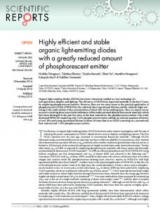
Figure 1. (a) Schematic diagram of layered MO NP-based QLEDs. (b) Energy levels diagram of MO NP-based QLEDs for the various layers.
properties compared with those of the organic counterparts, because of their good electron transport capability and interfacial phase compatibility with the QD layer.19 In addition, because of the need for sophisticated equipment and the possible physical damage introduced into QDs when utilizing thermal evaporation or sputtering, the spin-coating process is used in an attempt to resolve these problems, which provides cost effectiveness, solution processability, excellent stability, visible transparency, and controllable morphologies and interface structures of thin films at the nanometer length scale.20−22 Herein, we report a hybrid QLED based upon the doublesided inorganic MO nanoparticles (NPs) as CTLs (WO3 and ZnO NP layers employed as the ETL and HTL, respectively), in which all of materials are stable inorganic materials except poly[N,N′-bis(4-butylphenyl)-N,N′-bis(phenyl)benzidine] (poly-TPD). Poly-TPD has the advantages of good chemical resistance to organic solvents used for subsequent QD layer deposition and being widely used as the organic hole transporting material.23 The double-sided MO NP-based QLED is obtained by a facile spin-coating process. Such a device demonstrates a high luminance of 21300 cd/m2, a current efficiency (CE) of 4.4 cd/A, and a low turn-on voltage of 3 V. Meanwhile, the QLED lifetime of 95 h with an initial luminance of 600 cd/m2 is achieved in continuous operation under a N2 atmosphere.
by successive centrifugation, and then this emissive layer was prepared on top of the HTL by spin-coating at 2000 rpm, followed by annealing at 90 °C for 30 min. The ZnO nanoparticles dispersed in ethanol were prepared, as the ETL layer by spin-coating at a rate of 1000 rpm on top of the QD layer. Next, the multilayer samples were loaded into a high-vacuum deposition chamber (at a pressure of ≤1 × 10⁻⁴ Torr) to thermally deposit the cathode aluminum (Al), in which a shade mask was used to define the top Al contact and form an active device area of 9 mm2. We also fabricated a control device for comparing the device performance, in which the MO NP layers were substituted by thermal evaporation and sputtering. The optimized WO3 was thermally evaporated on the ITO substrate as the HTL in a deposition chamber, and the ZnO ETL was deposited onto QDs by radiofrequency magnetron sputtering at room temperature using a metallic zinc target in a gas mixture of argon and oxygen. Characterization. Atomic force microscopy (Cypher AFM, Asylum Research) was used to obtain the surface morphologies of the spin-coated WO3 and ZnO NP layers. The electroluminescence (EL) spectra of the fabricated devices were measured using a Photo Research PR705 Spectra Scan spectrometer, while the luminance− current−voltage characteristics of the devices were measured simultaneously with a programmable Yokogawa source meter (GS610) and a Konica Minolta luminance meter (LS-110) in air at room temperature. The devices were measured under ambient conditions without any encapsulation. The lifetimes of the QLEDs were tested in inert N2 at room temperature, and then the decay of brightness was measured under a constant current bias corresponding to an initial luminance of 600 cd/m.
2. EXPERIMENTAL SECTION
3. RESULTS AND DISCUSSION The device architecture of the MO NP-based QLED is schematically shown in Figure 1a. Specifically, the multilayer structure consisting of ITO, WO3 NPs (20 nm), poly-TPD (30 nm), QDs (20 nm), ZnO NPs (40 nm), and Al (190 nm) is used here, in which ITO serves as the anode, WO3 NPs and poly-TPD serve as the HTLs, ZnO NPs serve as the ETL, and Al serves as the cathode. Figure 1b illustrates the corresponding energy diagram of the MO NP-based QLED. As one can see, the hole transport material poly-TPD has a large band gap, which hinders the possibility of electrons from the lowest unoccupied molecular orbital (LUMO) level of QDs being collected at the ITO anode, resulting in a decrease in the extent of electron−hole recombination for the device. In addition, from our previous report, it is realized that the WO3 NPs have a work function of 5.15 eV, which is in favor of the injection of holes into QDs.25 This can be attributed to the extraction of ab electron from the highest occupied molecular orbital (HOMO) level of poly-TPD through the WO3 conduction band, and then into ITO.26 Moreover, the WO3 NPs are stable and therefore
Synthesis of ZnO and CdZnSeS Nanoparticles. The precursor solution for the ZnO layer was synthesized according to a previously reported method by Qian et al.19 The ZnO NPs were washed twice and finally dispersed in ethanol, yielding a concentration of ∼20 mg/ mL. Details of the synthetic method of cadmium selenide/zinc sulfidealloyed QDs can be found elsewhere.24 The colloidal QDs used as the emission layer have a photoluminescence quantum yield of ∼70% in solution. Fabrication of QLED Devices. For the MO NP-based QLED, the layers of WO3 NPs, poly-TPD, QDs, and ZnO NPs were sequentially deposited on ITO by solution processing. First, the prepatterned indium tin oxide (ITO) glass substrates were thoroughly cleaned (sequentially with a nonionic detergent, deionized water, acetone, and 2-propanol for 15 min each), followed by an O2 plasma treatment. Second, in an N2-filled glovebox, the WO3 nanoparticles with an average particle size of 7 nm in an ethanol solution (Nanograde GmbH, product no. 4035) was spin-coated at 5000 rpm on the ITO substrate and baked at 100 °C for 30 min, followed by spin-coating a layer of poly-TPD (ADS 254BE, dissolved in chlorobenzene), which was then annealed at 150 °C for 30 min. The QDs were dissolved in toluene (15 mg/mL) after the removal of the excessive organic ligands 496
dx.doi.org/10.1021/am404540z | ACS Appl. Mater. Interfaces 2014, 6, 495−499
ACS Applied Materials & Interfaces
Research Article
can act as a protection layer for the poly-TPD layer.27 For the ZnO, because of the low band offset for Al/ZnO and small energetic barrier with QDs, the electron transport and injection into QDs are quite efficient. Meanwhile, ZnO with a large band gap and low-valence band level is also favorable for exciton blocking.7,9 In the fabrication of the QLED, the morphology of thin film layers can significantly affect device performance. Therefore, a smooth surface is essential for obtaining a high-performance device. According to the three-dimensional atomic force microscopy (AFM) images shown in Figure 2a, the surface
devices. Moreover, because of the facilitated hole injection from WO3 NPs and poly-TPD as well as electron injection into QDs from ZnO NPs, the carrier recombination within the QD layer becomes more direct and efficient. This is a benefit of the pure emission solely from QDs allowing a spectrally pure QLED. Figure 3b presents the luminance and current density curves as a function of voltage for the MO NP-based QLED. This device shows a low turn-on voltage of 3 V, measured using a highsensitivity spectrometer. The results confirm the minimized barrier height for the injection of charge into the device, and then electrons and holes can be efficiently injected into the QDs even at low driving voltages. From the L−V characteristics, it yields a peak luminance of 21300 cd/m2 at the applied voltage of 10 V, which is comparable with the previously reported best brightness value in QLEDs with noninverted structure.25 Figure 3c illustrates the performances in terms of CE−EQE−V trends of the MO NP-based QLED. The maximal CE and EQE of the resulting device were measured to be 4.4 cd/A and 1.3%, respectively, at the applied voltage of 10 V, representing a more than 10-fold improvement over the previously reported structures of all-organic- and all-inorganicbased QLEDs.2,10,13 Figure 3d displays the photograph of the MO NP-based QLED at an applied voltage of 5 V, which exhibits uniform and bright green emission. As shown above, the hybrid QLED based upon the doublesided inorganic MO NP CTLs is demonstrated with excellent optical properties. Furthermore, the comparative experiments are conducted to demonstrate the superiority of solutionprocessed WO3 and ZnO NP CTLs. Thus, the control device is designed and fabricated, in which the optimized WO3 and ZnO layers are thermally evaporated (5 nm) and sputtered (50 nm), respectively. As shown in Figure 4a, the peak luminance and EQE of 2855 cd/m2 and 0.28%, respectively, are recorded for the optimized control device. Because of the nonradiative recombination of the excessive carriers (holes or electrons), dramatic decreases in luminance and EQE are observed. Figure 4b plots the J−V behaviors of the MO NP-based QLED and control device. Because the control device suffers from greatly unbalanced charge recombination, the turn-on voltage (6 V) is higher than that observed in the MO NP-based QLED (3 V). Obviously, the performance of the MO NP-based QLED is quite superior to that with thermally evaporated WO3 and sputtered ZnO layers. The functions of the WO3 and ZnO NPs can be explained in five ways. (1) Solution-processed WO3 and ZnO NP layers are compatible with QDs for the fabrication of bright and stable QLEDs. (2) The WO3 NPs can effectively improve the hole collection at the interface between the ITO electrode and the active layer.31 (3) The ZnO NP layer acts as an optical spacer and simultaneously an exciton blocking layer, improving electron injection in the QD layer. (4) The solution-processed ZnO NP ETLs do not affect the lower QD layer, while the sputtering process often damages the QD layer to a certain extent. (5) The efficient carrier recombination within QD layers occurs because of the facilitated charge carrier injection into QDs from WO3 and ZnO NP layers, as well as the enhanced charge carrier balance within the devices. All effects have a great influence on enhancing charge recombination in the QD layer. The variation in luminance is displayed as a function of time in Figure 5. The lifetime test of the double-sided inorganic MO NP-based QLED is performed by operating the device under a N2 atmosphere (oxygen concentration of ≤20 ppm) at a
Figure 2. AFM images of spin-coated (a) WO3 NP layers on ITO and (b) ZnO NP layers on the top of a multilayer structure consisting of ITO, WO3, poly-TPD, and QDs.
roughness (RMS) of the WO3 NP layer on top of the ITO electrodes is found to be