Manual on-line programming refers to physically teaching a robot the required trajectory .... Delmia has a Visual Basic editor in the main menu that allows.
Stamping line optimization using Genetic Algorithms and Virtual 3D line simulation. Authors: • Javier A. García-Sedano • Jon Alzola Bernardo • Asier González González
Authors: • Óscar Berasategui Ruiz de Gauna
• Rafael Yuguero González de Mendivil 1
Stamping line optimization using Genetic Algorithms and Virtual 3D line simulation. Author of the presentation: • Asier González González
2
Abstract This paper describes the use of a genetic algorithm (GA) in order to optimize the trajectory followed by industrial robots (IRs) in stamping lines. The objective is to generate valid paths or trajectories without collisions in order to minimize the cycle time required to complete all the operations in an individual stamping cell of the line. A commercial software tool is used to simulate the virtual trajectories and potential collisions, taking into account the specific geometries of the different parts involved: robot arms, columns, dies and manipulators. Then, a genetic algorithm is proposed to optimize trajectories. Both systems, the GA and the simulator, communicate as client - server in order to evaluate solutions proposed by the GA. The novelty of the idea is to consider the geometry of the specific components to adjust robot paths to optimize cycle time in a given stamping cell. 3
0. Index 1. Objective. 2. Stamping line. 2.1. Concepts. 2.2. Components. 3. Stamping cell. 3.1. Workpiece. 3.2. Claw 3.3. Pairs of Dies. 3.4. Press machine. 3.5. Industrial robots. 3.5.1.On-line. 3.5.2.Off-line.
4. Prototype architecture. 4.1. Delmia. 4.1.1. Tags. 4.1.2. Trajectories. 4.1.3. Cycle time. 4.2. Genetics Algorithm 4.3. Communication. 5. Prototype working schema. 6. Results. 6.1. Results of the first model. 6.2. Results of the second model. 6.3. Results of the third model.
4
1. Objetive The objective of this project is to describe a technique for finding optimal trajectory of industrial robots in a stamping line and considering the geometry of the specific components to optimize cycle time.
5
2. Stamping line Some Concepts:
• A stamping line is a set of press machines and industrial robots positioned in a straight line. • More than one press machine is needed because large pieces cannot be placed in a unique press machine. • The pieces that are produced in this type of stamping line are used in the automotive industry.
6
2. Stamping line Components: 1.
Feeding system: The Feeding system provides the raw material needed for manufacturing.
2.
First Press Machine: The first press machine performs the task of deforming the raw material. This is usually the bottleneck process of the stamping line. This first machine is responsible for providing higher deformation.
7
2. Stamping line 3.
Press Machines: They are responsible for shaping the final product. They make the cuts, bends and holes needed for the piece to take its final appearance.
4.
Output Stamping line: The stack of pieces can be done manually by operators or automatically by robots.
5.
Industrial Robots: The industrial robots are responsible for transporting pieces between presses.
8
3. Stamping cell A Stamping cell is formed by a subsystem consisting of an Intermediate press machine of the stamping line and two industrial robots.
One industrial robot introduces the piece in the press machine and the other industrial robot extracts the piece from the press machine. The different parts, that composes the stamping cell, are: – – – – –
3.1. Workpiece 3.2. Claws 3.3. Pairs of Dies 3.4. A press machine. 3.5. Two Industrial robots.
9
3.1. Workpiece The workpiece or piece is a part of material that is worked out to obtain the final product.
In the examples, we have different pieces that are used in the automotive industry.
10
3.2. Claw Claw is a mechanical device that permits to suspend or hold the workpiece. The claw is connected with the industrial robot and moves with it. In this case, the claw is pneumatic to avoid the abrasion marks in the piece.
11
3.2. Claw Claw is a mechanical device that permits to suspend or hold or pull the workpiece. The claw is connected with the industrial robot and move with it. In this case, the claw is pneumatic to avoid the abrasion marks in the piece. suction pad (ventosa)
12
3.3. Pairs of Dies A die is a tool used in manufacturing industries to cut or shape material using a press. Upper Die of the press machine.
Lower Die of the press machine.
13
3.3. Pairs of Dies Upper Die of the press machine.
Lower Die of the press machine. 14
3.4. Press Machine The press machine performs a periodic task is divided into two stages: •T1
•T2
15
3.4. Press Machine (T1) • The time „T1‟ is the time that the two robots are performing their operations (pick the piece and load/unload it) • This time „T1‟, could be optimize by modifying the trajectories of industrial robots.
16
3.4. Press Machine (T2) •Closing: Is the time that the press machine spend in connecting the upper die to the lower die. • Pressing: Is the time that the press machine presses the piece with the pair of dies. • Opening. Is the time that the press machine spends in separate the upper die for the lower die. The time „T2‟ is a fixed time that is composed by:
17
3.5. Industrial robots. An industrial robot is an automatically controlled, reprogrammable, multipurpose manipulator programmable in three or more axes.
Industrial robots have the functions: – Transporting the material between the press machines. – To provide the Feeding system with material. – To Stack finished pieces.
Method of programming industrial robots: • Manual on-line programming. • Off-line programming.
18
3.5.1. Manual on-line programming Manual on-line programming refers to physically teaching a robot the required trajectory, through interaction with teach pendant or other similar device.
Advantages: • No testing is required because the robot is programmed into the real situation. Disadvantages: • It needs that the robot is available. • The productive process needs to be stopped. • More expensive. • Very slow. • Difficulty in the handling of equipments. • knowledge in the language used by the robot. • Technical knowledge to understand the operation of the equipment. • Possible collision. 19
3.5.2. Off-line programming Off-line programming: it is based in graphical simulation platforms, in which the programming and execution process are shown using models of the real objects. Disadvantages:
• Testing is required because the robot is programmed into the simulator.
Advantages: • The robot programmer has to learn only the simulation language and not any of the robot programming languages. • It is possible to include all the elements involved around the industrial robots and planning trajectories for industrial robot to avoid collisions. • The cycle time is possible to be determined. 20
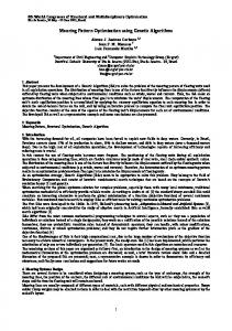
4. Prototype architecture • • •
The trajectories of IRs are simulated with Delmia software Simulator. The genetic algorithm optimizes the trajectories of Industrial Robots. The link between the genetic algorithm and Delmia is achieved via Microsoft’s Component Object Model (COM) interface.
1. The GA changes the Delmia tags by COM interface. 2. Delmia simulates the model. 3. Delmia returns to GA the existence of collision and cycle time.
Delmia Simulator (Server)
Tags
Tags
COM Collision Cycle time
Collisio n
Genetic Algorithm (Client)
Cycle t ime 21
4.1. Delmia •
DELMIA (Digital Enterprise Lean Manufacturing Interactive Application) is the brand for digital manufacturing and simulation solutions from Dassault Systemes.
•
Delmia V5 is a software of a virtual manufacturing tool that allows to define, plan, create, visualize and control production processes, among many other functionalities.
•
It is possible to simulate a process, and then translate IR tasks into IR controller-specific programming languages.
•
The version of Delmia that we use is V5 R18.
•
The documentation of Delmia V5 R18 is available in Dassault Systemes. www.3ds.com
22
4.1.1. Tags Tags represent the points in the space that Industrial Robots' claws must pass through in their trajectories.
Each tag has a position in the space defined by three dimensional space variables (x, y, z) and three angles (yaw, pitch, roll).
23
4.1.2. Trajectories Trajectories defined are programmed in the Delmia virtual process, then they can be tested by performing a simulation.
– If all trajectories of IRs have been performed without incidents, the result is a correct simulation. – If collisions have happened or unreachable points have been found along the simulation execution, then the result is a faulty simulation.
24
4.1.3. Cycle time The cycle time is the sum of times that needs the simulation to finished.
T1 + T2 = Cycle time
25
4.2. Genetic Algorithm Individuals
•An individual is a valid solution for the problem. •The genome of each individual includes: – A matrix of the spatial coordinates (x, y, Z) and angles (yaw, pitch, roll).) of each tag points. –The fitness function is the “cycle time” in seconds.
Fitness/Cost Function:
• The fitness function is the cycle time.
Constraints:
No collisions and unreachable points
Initialization:
Initial solution Line Programmer Experience
26
4.2. Genetic Algorithm Selection:
Crossover mutation operators:
Roulette Wheel Selection.
and uniform crossover and uniform mutation Mutation probability = 0.5 .
27
4.2. Genetic Algorithm
Replacement:
• The size of the population is fixed in 20 individuals. • The Worst Among Most Similar Replacement (WAMS), has been chosen to replace the individuals in order to improve the population.
Stopping criteria:
Optimization stops when: • A number of generations has been reached. • The value of best cycle-time does not decrease over a number of generations. • The execution time limit is overridden.
28
4.3. Communication Component Object Model (COM): •
Delmia has a Visual Basic editor in the main menu that allows communicating with an external program.
• •
The Genetic Algorithm has been developed in C++ with Microsoft Visual Studio. The communication between Delmia and the Genetic Algorithm has been achieved by COM interfacing technology. 29
5. Prototype working schema Schema: 1. The GA software must be executed. 2. A valid process model, without collisions or unreachable points, has to be ready in the Delmia Simulator.
4.
The GA software performs optimization, following these steps:
4.1. GA creates its first individual genome with the matrix of tags of the initial solution. The cycle time is given by the simulator and it corresponds to the fitness value of the individual.
30
5. Prototype working schema 4.2. Repeat
– 4.2.1. Mutation operator is used to create a new genome. – 4.2.2. Delmia simulates, automatically, the matrix of tags of the new genome. • If the simulation is correct, a new individual is created with the genome and the cycle time as fitness value. This individual is inserted in the population. • If the simulation has collisions or unreachable points the genome is discarded.
Until fill the population
31
5. Prototype working schema 4.3. Repeat – 4.3.1. New genomes are generated using selection, crossover and mutation operators. – 4.3.1. Delmia simulates, automatically, the matrix of tags of each new genome. • If the simulation is correct, a new individual is created with the genome and the cycle time as fitness value. This individual can be inserted in the population using replacement operator. • If the simulation has collisions or unreachable points the genome is discarded.
Until stopping criteria is reached. 32
6.1. Results of the first model
33
6.1. Results of the first model
Solution
Time
Improvement
Initial valid solution
17.326 s
Manual solution after two hours of work
16.853 s
0.473 s (2.5 %)
GA solution after two hours of automatic 16.753 s work
0.573 s (3.1 %) 34
6.2. Results of the second model
35
6.2. Results of the second model
Solution
Time
Improvement
Initial valid solution
17.918 s
Manual solution after two hours of work
16.677 s
1.241 s (6.9 %)
GA solution after two hours of automatic 16.527 s work
1.391 s (7.8 %) 36
6.3. Results of the third model
37
6.3. Results of the third model
Solution
Time
Improvement
Initial valid solution
17.997 s
Manual solution after two hours of work
17.032 s
0.965 s (5.4 %)
GA solution after two hours of automatic 16.848 s work
1.049 s (6.5 %) 38
Thanks for your attention
39