Documenta Ophthalmologica 101: 11–18, 2000. © 2000 Kluwer Academic Publishers. Printed in the Netherlands.
Standard for pattern electroretinography MICHAEL BACH1,∗ , MARKO HAWLINA2, GRAHAM E. HOLDER3, MICHAEL F. MARMOR4, THOMAS MEIGEN5, VAEGAN 6 and YOZO MIYAKE7,∗ (for the International Society for Clinical Electrophysiology of Vision) From 1 Univ.-Augenklinik, Freiburg, Germany; 2 University Eye Clinic, Ljubljana, Slovenia; 3 Moorfields Eye Hospital, London, UK; 4 Department of Ophthalmology, Stanford (Calif.) University School of Medicine; 5 Univ.-Augenklinik, Würzburg; Germany; 6 Visiontest Australia, Sydney, Australia; and 7 Nagoya University School of Medicine, Nagoya, Japan Accepted 25 May 2000
Abstract. The pattern electroretinogram (PERG) is a retinal response evoked by viewing an alternating checkerboard or grating. It receives clinical and research attention because it can provide information about inner retinal cells and the macula. However, clinicians may have trouble choosing between different techniques for recording the PERG that have been described in the literature. The International Society for Clinical Electrophysiology of Vision has prepared a standard for a basic PERG recording procedure to aid new users in obtaining reliable responses and to encourage more uniformity among existing users. Key words: clinical electrophysiology, electroretinogram, pattern electroretinogram
Introduction The pattern electroretinogram (PERG) is a retinal biopotential that is evoked when a temporally modulated patterned stimulus of constant total luminance (checkerboard or grating) is viewed. The PERG is most often evoked by alternating reversal of a checkerboard pattern. It may be altered in dysfunction of the macula or of the inner retina selectively, which do not significantly affect the conventional full-field ERG. The PERG receives clinical and research attention in both neurological and ophthalmological practice. However, the PERG is a very small signal, typically in the region of 0.5–8 µV depending on stimulus characteristics, and PERG recording is technically more demanding than the conventional ERG. Recordings published in the literature vary considerably in technical quality as well as technique, and new users may find it difficult to choose which technique to use. ∗ M. Bach chaired the PERG Standardization Committee and Y. Miyake is President of the ISCEV.
12 The International Society for Clinical Electrophysiology of Vision (ISCEV) feels that there is now a sufficient body of knowledge and clinical experience to propose a standard for performing a basic PERG. This document evolved from the ‘PERG Guidelines’ [1] and is intended as a guide to practice and to assist in interpretation of PERGs. Transient PERG as described below represents the minimum of what a PERG evaluation should include. The standard describes simple technical procedures that allow reproducible PERGs to be recorded under a few defined conditions. Different procedures may provide equivalent PERG responses. It is incumbent on users of alternative techniques to demonstrate that their procedures do in fact produce signals that are equivalent in basic waveform, amplitude, and physiologic significance to the standard. Our intention is that the standard method and responses be used widely, but not to the exclusion of other paradigms that individual laboratories may use, tailored to their own requirements. The standard is based upon equipment and analytic capabilities currently found in most neurophysiological or ophthalmological electrodiagnostic clinics. This document addresses recording conditions and technology specific to the PERG, and presumes that readers already have basic understanding and skills in clinical electrophysiology. Although much of this document will apply equally to adults and children, the standard is not necessarily appropriate to paediatric applications. The standard will be reviewed by ISCEV every four years.
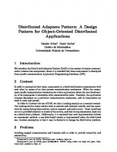
Waveform nomenclature and measurement The waveform of the PERG evoked by pattern-reversal stimuli depends on the temporal frequency of the stimulus. By convention, positivity is displayed upward. Transient PERG At low temporal frequencies (6 reversals per second or less, equivalent to 3 Hz or less) a transient PERG is obtained (Figure 1). The waveform is characterised by a small initial negative (N) component, at approximately 35 ms, which will be referred to as N35. This is followed by a later and larger positive (P) component (45–60 ms) which is typically denoted as P50. This positive portion of the waveform is followed by a large negative component at about 90–100 ms (N95). For the transient PERG, amplitude measurements are made between peaks and troughs: The P50 amplitude is measured from the trough of N35 to the peak of P50. In some patients the N35 is poorly defined; in these cases N35
13
Figure 1. Transient PERG. Parameters: check size 0.8◦ , field size 15◦ ×15◦ , contrast 98%, mean luminance 45 cd/m2 , 4.5 reversals/s.
is replaced by the average between time zero and the onset of P50. The N95 amplitude is measured from the peak of P50 to the trough of N95. It should be recognised that measured in this way, N95 includes the P50 amplitude. Latency measurements should be taken from the onset of the stimulus to the peak of the component concerned; inexperienced workers should note that the highest absolute amplitude point on a waveform will not always be appropriate for the definition of the peak if there is contamination from muscle activity or other artifacts. The peak should be designated where it would appear on a smoothed or idealised waveform. Steady-state PERG At higher temporal frequencies, i.e. above 10 rev/s (5 Hz), the successive waveforms overlap and a ‘steady-state’ PERG is evoked. The waveform becomes roughly sinusoidal, and Fourier analysis is required to determine the amplitude and temporal phase shift (relative to the stimulus).
Basic technology Electrodes Recording electrodes. Electrodes that contact the cornea or nearby bulbar conjunctiva are recommended. This does not include contact lens electrodes or any other electrodes that degrade image quality on the retina. Thin conductive fibres, foils and loops can usually be positioned without topical anaesthesia. Those who perform the test should be aware of possible causes of artifact. Electrode integrity should be checked prior to insertion, to meet guidelines for each electrode type. Note: Some instruments can cause patient
14 harm when impedance is measured in situ. Electrodes should be carefully positioned to minimise instability (a major source of artifact or interference). • Fibre electrodes should be placed in the lower fornix. Draping the electrode across the lower eyelashes at the medial canthus, or taping it to the cheek, may help to stabilise it. • Foil electrodes should be positioned directly under the centre of the pupil so that there is minimal or no movement of the electrode when the patient blinks. This is best achieved by having the foil curve over the lower eyelashes without contacting them, and then tethering the lead to the cheek. The junction of the electrode and lead should form as straight a line as possible and the junction should not touch the skin. • Loop electrodes should be hooked into the lower fornix. Loops should be folded so that the contact windows on otherwise insulated wire are positioned on the bulbar conjunctiva, about 5 mm under the limbus. Loop electrodes should not touch the cornea. To achieve this, the limbs of the loop should be diverged widely (15-20 mm) before entering the fornix. The lead is then taped to the cheek. The appropriate techniques for individual electrode types are very important to achieve stable and reproducible PERG recordings. Additional sources should be consulted in relation to the specific electrode used. Reference electrodes. Surface reference electrodes should be placed at the ipsilateral outer canthi. Mastoid, earlobe or forehead locations may result in contamination of the PERG from cortical potentials or the fellow eye. If monocular PERG recording is performed, the electrode in the occluded eye may be used as a reference. Ground electrodes. A separate surface electrode should be attached and connected to the amplifier ‘ground input’; the forehead would be a typical location. Surface electrode characteristics. The impedance between the skin electrodes used for reference and ground, measured on the subject, should be less than 5 k. The skin should be prepared with a suitable cleaning agent, and a suitable conductive paste should be used to ensure good electrical connection. Since the electrode in the eye will have a very low impedance, low impedance of the reference electrode is especially important for optimal rejection of (common-mode) electrical interference. Electrode cleaning and sterilisation. ERG [2].
See ISCEV Standard for full-field flash
15 Stimulus parameters This standard outlines only a basic protocol for PERG recording. Laboratories may choose to test more conditions or parameters than are described herein. Field and check size. For the ‘basic PERG’, we recommend using a black and white reversing checkerboard with a stimulus field size between 10◦ and 16◦ , and a check size of approximately 0.8◦ . For some applications, such as glaucoma assessment, a larger extent such as 30◦ may be more appropriate. Contrast. For the ‘basic PERG’ the contrast between black and white squares should be maximal (close to 100%) and not less than 80%. Luminance. PERGs are difficult to record with low stimulus luminance, and a photopic luminance level for the white areas of greater than 80 cd m−2 is recommended. Overall screen luminance must not vary during checkerboard reversals. Frame rate. Raster-based CRTs are typically used to present the pattern stimuli. The frame rate of the CRT is a significant stimulus parameter for PERUs, and a frequency of 75 Hz or greater is recommended. Background illumination. The luminance of the background beyond the checkerboard field is not critical when using the suggested PERG technique as long as dim or ordinary room lighting is used; ambient lighting should be the same for all recordings. Care should be taken to keep bright lights out of the subjects’ direct view. Transient and steady-state recording. As a ‘basic PERG’ protocol, we recommend that laboratories record the transient PERG as it allows separation of the P50 and N95 components. There are also situations in which the steady-state PERG is useful; some laboratories favour it for glaucoma studies. Since little extra time is required, laboratories should consider recording it as well. Keep in mind, however, that the proper interpretation of steady-state PERGs requires measurement of amplitude and phase shift (relative to the stimulus) of the second harmonic by Fourier analysis. A significant first harmonic indicates technical problems. We do not recommend steady-state PERG recording without instrumentation for such analysis, and we caution that steady-state stimulation at reversal rates below our recommendation (16 rev/s) requires special equipment to modulate contrast sinusoidally.
16 Reversal rate. For transient PERG we recommend 2–6 reversals per second (1–3 Hz); for steady-state PERG, we recommend 16 reversals per second (8 Hz). Recalibration.
We advise regular stimulus recalibration [3].
Recording equipment Amplification systems. AC-coupled amplifiers with a minimum input impedance of 10 M are recommended. Amplification systems should be electrically isolated from the patient according to the current standards for safety of biologic recording systems used clinically. We recommend that the frequency response of bandpass amplifiers should include the range from 1–100 Hz, and that notch filters (that suppress signals at the alternating current line frequency) not be used. Some users may encounter severe electromagnetic interference that makes it difficult to obtain responses with these filter recommendations. Ideally, such interference should be eliminated by shielding or modifying equipment; rearranging the electrode leads may be of benefit. Laboratories using stronger filtering or a notch filter must recognise that their responses may not be comparable to those from other laboratories, and should note in reports that extra filtering was applied. Averaging and signal analysis. Because of the small amplitude of the PERG, signal averaging is always necessary. For transient PERGs the analysis period (sweep time) should be 150 ms or greater. A Fourier analysis program will be needed if steady-state PERGs are to be recorded, and the analysis period must be a multiple of the stimulus interval (e.g. 8). Artifact rejection. Computerised artifact rejection is essential, and we recommend that this should be set at no higher than 100 µV peak-to-peak, and preferably less. The amplifiers must return to baseline rapidly following artifactual signals to avoid inadvertent storage of non-physiological data. Data display systems. Display systems must have adequate resolution to represent accurately the characteristics of this small amplitude signal. Optimal conditions allow for simultaneous display of input signal and average. In the absence of a simultaneous display, the system should allow a rapid alternation between input signal display and average display. Thus the quality of the input signal can adequately be monitored. Even with a computerised artifact rejection system, it is important that the input signal be monitored for baseline stability and the absence of amplifier blocking.
17 Clinical protocol Preparation of the patient Positioning. The patient should be positioned as comfortable as possible and leaning against a head-rest. Pupils. The PERG should be recorded without dilatation of the pupils, to preserve accommodation and thus retinal image quality. Fixation. A fixation spot in the centre of the screen is essential. If there are any doubts about the quality of fixation in an individual patient, an effective method is to give the patient a pointer and have them point at the middle of the screen throughout. Excessive blinking during recording should be discouraged, pauses may be advantageous. Refraction. Because of the nature of the stimulus, PERG examination should be performed with optimal visual acuity at the testing distance. Patients should wear the appropriate optical correction for the test distances. Monocular and binocular recording. Proper positioning of recording and reference electrodes will permit either monocular or binocular recording of the PERG. Binocular recording of the PERG is recommended for the ‘basic PERG’ because it is generally more stable, it reduces examination time and it allows fixation by the better eye in cases of asymmetric visual loss. Monocular stimulation is required to simultaneously record the PERG and the VEP. Recording. Typically, 150 responses should be averaged, and more may be needed with a ‘noisy’ subject. At least two full recordings of each stimulus condition should be obtained to confirm responses (i.e. one replication). PERG reporting Reporting. It is recommended that all reports contain measurements of P50 and N95 amplitude (see above), and P50 latency (the peak of N95 is often rather broad precluding accurate latency measurement of this component). If steady-state PERGs are performed, amplitude and phase shift of the second harmonic should be reported. All reports should also contain the stimulus parameters and the normal values for the laboratory concerned. Whenever practical, reporting of PERG results should include representative waveforms with appropriate amplitude and time calibrations.
18 Clinical norms. Each laboratory should establish normal values for its own equipment and patient population. It should be noted that there are PERG changes with age. Note:
This document is available on the ISCEV website .
References 1. Marmor MF, Holder GE, Porciatti V, Trick GL, Zrenner E. Guidelines for basic pattern electroretinography. Recommendations by the International Society for Clinical Electrophysiology of Vision. Doc Ophthalmol 1996; 91: 291–298 2. Marmor MF, Zrenner E. Standard for clinical electroretinography (1999 update). Doc Ophthalmol 1999; 97: 143–156 3. Brigell M, Bach M, Barber C, Kawasaki K, Kooijman A. Guidelines for calibration of stimulus and recording parameters used in clinical electrophysiology of vision. Doc Ophthalmol 1998; 95: 1–14
Address for correspondence: M. Bach, Univ.-Augenklinik, Killianstr. 5, D-79106 Freiburg, Germany E-mail:
[email protected]