Abstract. As networks become faster there is an emerging need for security
analysis ... Keywords: Intrusion Detection, High-Speed Networks, Se- curity
Analysis.
Stateful Intrusion Detection for High-Speed Networks Christopher Kruegel Fredrik Valeur Giovanni Vigna Richard Kemmerer Reliable Software Group University California, Santa Barbara kruegel,fredrik,vigna,kemm�@cs.ucsb.edu
Abstract As networks become faster there is an emerging need for security analysis techniques that can keep up with the increased network throughput. Existing network-based intrusion detection sensors can barely keep up with bandwidths of a few hundred Mbps. Analysis tools that can deal with higher throughput are unable to maintain state between different steps of an attack or they are limited to the analysis of packet headers. We propose a partitioning approach to network security analysis that supports in-depth, stateful intrusion detection on high-speed links. The approach is centered around a slicing mechanism that divides the overall network traffic into subsets of manageable size. The traffic partitioning is done so that a single slice contains all the evidence necessary to detect a specific attack, making sensorto-sensor interactions unnecessary. This paper describes the approach and presents a first experimental evaluation of its effectiveness. Keywords: Intrusion Detection, High-Speed Networks, Security Analysis.
1 Introduction Network-based intrusion detection systems (NIDSs) perform security analysis on packets obtained by eavesdropping on a network link. The constant increase in network speed and throughput poses new challenges to these systems. Current network-based IDSs are barely capable of real-time traffic analysis on saturated Fast Ethernet links (100 Mbps) [3]. As network technology presses forward, Gigabit Ethernet (1000 Mbps) has become the de-facto standard for large network installations. In order to protect such installations, a novel approach for network-based intrusion detection is necessary to manage the ever-increasing data volume.
Network speeds have increased faster than the speed of processors, and therefore centralized solutions have reached their limit. This is especially true if one considers in-depth, stateful intrusion detection analysis. In this case, the sensors have to maintain information about attacks in progress (e.g., in the case of multi-step attacks) or they have to perform application-level analysis of the packet contents. These tasks are resource intensive and in a single-node setup may seriously interfere with the basic task of retrieving packets from the wire. To be able to perform in-depth, stateful analysis it is necessary to divide the traffic volume into smaller portions that can be thoroughly analyzed by intrusion detection sensors. This approach has often been advocated by the highperformance research community as a way to distribute the service load across many nodes. In contrast to the case for standard load balancing, the division (or slicing) of the traffic for intrusion detection has to be performed in a way that guarantees the detection of all the threat scenarios considered. If a random division of traffic is used, sensors may not receive sufficient data to detect an intrusion, because different parts of the manifestation of an attack may have been assigned to different slices. Therefore, when an attack scenario consists of a number of steps, the slicing mechanism must assure that all of the packets that could trigger those steps are sent to the sensor configured to detect that specific attack. This paper presents an approach to in-depth, stateful intrusion detection analysis and a tool based on this approach. The approach allows for meaningful slicing of the network traffic into portions of manageable size. The slicing approach and a tool based on the approach are presented in Section 3, after a discussion of related work in Section 2. Section 4 presents the results of the quantitative evaluation of the first prototype of the tool. Section 5 presents some final remarks and outlines future research.
2 Related Work The possibility of performing network-based intrusion detection on high-speed links (e.g., on OC-192 links) has been the focus of much debate in the intrusion detection community. A common position is to state that high-speed network-based intrusion detection is not practical because of the technical difficulties encountered in keeping pace with the increasing network speed and the more widespread use of encrypted traffic. Others advocate locating highly distributed network-based sensors at the periphery of computer networks; the idea being that the traffic load is, possibly, more manageable there. Even though both of the advocated approaches above have good points, analysis of network traffic on high-speed links still represents a fundamental need in many practical network installations. The commercial world attempted to respond to this need and a number of vendors now claim to have sensors that can operate on high-speed ATM or Gigabit Ethernet links. For example, ISS [4] offers NetICE Gigabit Sentry, a system that is designed to monitor traffic on high-speed links. The company advertises the system as being capable of performing protocol reassembly and analysis for several application-level protocols (e.g. HTTP, SMTP, POP) to identify malicious activities. The tool claims to be the “first network-IDS that can handle full Gigabit speeds.” However, the authors of the tool also state that “GigaSentry handles a full Gigabit in lab conditions, but real-world performance will likely be less. [. . . ] Customers should expect at least 300 Mbps real-world performance, and probably more depending up the nature of their traffic. [. . . ] GigaSentry can only capture slightly more than 500,000-packets/second.” These comments show the actual difficulties of performing network-based intrusion detection on high-speed links. Other IDS vendors (like Cisco [1]) offer comparable products with similar features. Unfortunately, no experimental data gathered on real networks is presented. TopLayer Networks [11] presents a switch that keeps track of application-level sessions. The network traffic is split with regard to these sessions and forwarded to several intrusion detection sensors. Packets that belong to the same session are sent through the same link. This allows sensors to detect multiple steps of an attack within a single session. Unfortunately, the correlation of information between different sessions is not supported. This could result in missed attacks when attacks are performed against multiple hosts (e.g., ping sweeps), or across multiple sessions. Very few research papers have been published that deal with the problem of intrusion detection on high-speed links. Sekar et al. [10] describe an approach to perform highperformance analysis of network data, but unfortunately they do not provide experimental data based on live traffic analysis. Their claim of being able to perform real-time
intrusion detection at 500 Mbps is based on the processing of off-line traffic log files. This estimate is not indicative of the real effectiveness of the system when operating on live traffic.
3 A Slicing Approach to High-Speed Intrusion Detection The problem of intrusion detection analysis in highspeed networks can be effectively attacked only if a scalable solution is available. Let us consider the traffic on the monitored network link as a bi-directional stream of linklayer frames (e.g., Ethernet frames). This stream contains too much data to be processed in real-time by a centralized entity and has to be divided into several smaller streams that are fed into a number of different, distributed sensors. Each sensor is only responsible for a subset of all detectable intrusion scenarios and can therefore manage to process the incoming volume in real-time. Nevertheless, the division into streams has to be done in a way that provides each sensor with enough information to detect exactly the same attacks that it would have witnessed when operating directly on the network link.
3.1 Requirements The overall goal is to perform stateful intrusion detection analysis in high-speed networks. The approach presented in this paper can be characterized by the following requirements. The system implements a misuse detection approach where signatures representing attack scenarios are matched against a stream of network events. Intrusion detection is performed by a set of sensors, each of which is responsible for the detection of a subset of the signatures. Each sensor is autonomous and does not interact with other sensors. The system partitions the analyzed event stream into slices of manageable size. Each traffic slice is analyzed by a subset of the intrusion detection sensors. The system guarantees that the partitioning of traffic maintains detection of all the specified attack scenarios. This implies that sensors, signatures, and traffic slices are configured so that each sensor has access to the traffic necessary to detect the signatures that have been assigned to it.
ID Sensors
Outside Internet
Switch
Reassemblers
Slicers
Scatterer
Tap
Inside
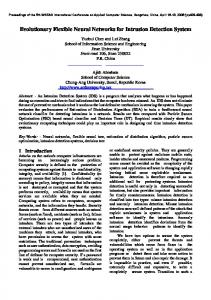
Figure 1. High-level architecture of the high-speed intrusion detection system. Components can be added to the system to achieve higher throughput. More precisely, the approach should result in a scalable design where one can add components as needed to match increased network throughput.
3.2 System Architecture The requirements listed in the previous section have been used as the basis for the design of a network-based intrusion detection system. The system consists of a network tap, a traffic slicers traffic scatterer, a set of �, a switch, a set of stream reassemblers � � , and a set of intrusion detection sensors � � . A highlevel description of the architecture is shown in Figure 1. The network tap component monitors the traffic stream on a high-speed link. Its task is to extract the sequence of link-layer frames � � � � that are observable on the wire during a time period . This sequence of frames into subis passed to the scatterer which partitions sequences � � . Each � contains a (possibly empty) subset of the frame sequence . Every frame � is an element of exactly one sub-sequence � and therefore ��� . The scatterer can use any algorithm to parti�� � tion . Hereafter, it is assumed that the splitting algorithm simply cycles over the sub-sequences in a round-robin
� ������ � ������ � ������
�
�
�
� �����
� �� �
� �� �
�
�
�
�
�
�
fashion, assigning � to � mod� � . As a result, each � contains an -th of the total traffic. Each sub-sequence � is transmitted to a different traffic slicer � . The task of the traffic slicers is to route the frames they receive to the sensors that may need them to detect an attack. This task is not performed by the scatterer, because frame routing may be complex, requiring a substantial amount of time, while the scatterer has to keep up with the high traffic throughput and can only perform very limited processing per frame. The traffic slicers are connected to a switch component, which allows a slicer to send a frame to one or more of outgoing channels � . The set of frames sent to a channel is denoted by � . Each channel � is associated with a stream reassembler component � and a number of intrusion detection sensors. The set of sensors associated with channel � is denoted by � . All the sensors that are associated with a channel are able to access all the packets sent on that channel. The original order of two packets could be lost if the two frames took different paths over distinct slicers to the same channel. Therefore, the reassemblers associated with each channel make sure that the packets appear on the channel in the same order that they appeared on the high-speed link. That is, each reassembler � must make sure that for each pair of frames � � � � it holds that ( � before � ) �� .
�
�
�
�
�
�
�
� �
�
� � � � ������
�
Each sensor component � is associated with different attack scenarios � � � �� � . Each attack scenario �� has an associated event space �� . The event space specifies which frames are candidates to be part of the manifestation of the attack. For example, consider an attack targeting a Web server called spider within the network protected by the intrusion detection system. In this case, the event space for that attack is composed of all the TCP traffic that involves port 80 on host spider. Event spaces are expressed as disjunctions of clauses, that is, �� ��¼ ��½ ��� , where each clause . denotes a value �� is an expression of the type derived from the frame � (e.g., a part of the frame header) while specifies an arithmetic relation (e.g., =, !=, ). can be a constant, the value of a variable, or a value derived from the same frame. Clauses and event spaces may be derived automatically from the attack descriptions, for example from signatures written in attack languages such as Bro [6], Sutekh [7], STATL [2], or Snort [8].
�
�
� ��
�
�
�
��� � ��� �
� �
3.3 Frame Routing Event spaces are the basis for the definition of the filters used by the slicers to route frames to different channels. The filters are determined by composing the event spaces associated with all the scenarios that are “active” on a specific channel. More precisely, the set of active scenar�� ios is � �� � where � is the set of scenarios of � � � . The event space � for a channel � is the disjunction of the event spaces of all active scenarios, which corresponds to the disjunction of all the clauses of all the active scenarios. The resulting overall expression is the filter that each slicer uses to determine if a frame has to be routed to that specific channel. Note that it is possible that a certain frame will be needed by more than one scenario. Therefore, it will be sent on more than one channel. The configuration of the slicers as described above is static; that is, it is calculated off-line before the system is started. The static approach suffers from the possibility that, depending on the type of traffic, a large percentage of the network packets could be forwarded to a single channel. This would result in the overloading of sensors attached to that channel. The static configuration also makes it impossible to predict the exact number of sensors that are necessary to deal with a Gigabit link. The load on each sensor depends on the scenarios used and the actual traffic. The minimum requirement for the slicers is that the capacity of their incoming and outgoing links must be at least equal to the bandwidth of the monitored link. One way to prevent the overloading condition is to perform dynamic load balancing. This is done by reassigning scenarios to different channels at run-time. This variant obviously implies the need to reconfigure the filter mechanism
� � � � � �
� �
at the traffic slicers and update the assignment of clauses to channels. In addition to the reassignment of whole scenarios to different channels, it is also possible to split a single scenario into two or more refined scenarios. The idea is that each refined scenario catches only a subset of the attacks that the original scenario covered, but each can be deployed on a different channel. Obviously, the union of attacks detectable by all refined scenarios has to cover exactly the same set of attacks as the original scenario did. This can be done by creating additional constraints on certain attributes of one or more basic events. Each constraint limits the number of attacks a refined scenario can detect. The constraints have to be chosen in a way such that every possible value for a certain attribute (of the original scenario) is allowed by the constraint of at least one refined scenario. Then the set of all refined scenarios, which each cover only a subset of the attacks of the original one, are capable of detecting the same attacks as the original. A simple mechanism to partition a particular scenario is to include a constraint on the destination attribute of each basic event that represents a packet which is sent by the attacker. One has to partition the set of possible destinations such that each refined scenario only covers attacks against a certain range of hosts. When the union of these target host ranges covers all possible attack targets, the set of refined scenarios is capable of finding the same attacks as the original scenario. Such an approach is necessary when a single scenario causes too much traffic to be forwarded to a single channel. In addition, obviously innocent or hostile frames could be filtered out before the scenario clauses are applied, thereby eliminating traffic that needs no further processing. This could be used, for instance, to prevent the system from being flooded by packets from distributed denial-of-service slaves that produce traffic with a unique, known signature.
4 Evaluation The initial set of experiments were primarily aimed at evaluating the effectiveness of the scatterer/slicer/ reassembler architecture. For these experiments, we deployed three ) and four stream reassemblers ( ) traffic slicers ( with one intrusion detection sensor per stream. The next section presents the details of the hardware and software used to realize the initial prototype, and the section after that gives the details of each experiment and presents the corresponding results.
��
���
4.1 Prototype Architecture The prototype is composed of a number of hosts responsible for the analysis of the traffic carried by a Gigabit link.
The Gigabit link is realized as a direct connection (crossover cable) between two machines equipped with Intel Xeon 1.7 GHz processors, 512 MB RAM and 64-bit PCI 3Com 996-T Gigabit Ethernet cards running Linux 2.4.2 (Red Hat 7.1). One of the two machines simulates the network tap and is responsible for creating the network traffic (via tcpreplay [12]). The other machine acts as the traffic scatterer and is equipped with three additional 100 Mbps 3Com 905C-TX Ethernet cards. The scatterer functionality itself is realized as a kernel module attached to the Linux kernel bridge interface. The bridge interface provides a hook that allows the kernel to inspect the incoming frames before they are forwarded to the network layer (e.g., the IP stack). The scatterer module intercepts frames coming from the Gigabit interface and immediately forwards them to one of the outgoing links through the corresponding fast Ethernet card. The links are selected in a round-robin fashion. The scatterer also attaches a sequence number to each packet, which is later used by the reassemblers. In order to overcome the problem of splitting Ethernet frames with a length close to the maximum transferable unit (MTU), the sequence number has to be integrated into the Ethernet frame without increasing its size. To leave the data portion untouched, we decided to modify the Ethernet header. We also wanted to limit the modifications of the Ethernet frame to a minimum in order to be able to reuse existing hardware (e.g., network interface cards, network drivers). Therefore, the MTU had to remain unchanged. For this reason, we decided to use the six-byte Ethernet source address field for sequence numbers. As a result, before the traffic scatterer forwards a frame, it writes the current sequence number into the source address field and increments it. The experimental setup demonstrates that the partitioning of traffic is possible and that it allows for the detailed analysis of higher traffic volume (including defragmentation, stream reassembly, and content analysis). Because we only use three traffic slicers (with an aggregated bandwidth of 300 Mbps), sustained incoming traffic of 1 Gbps would overload our experimental setup. However, the introduction of additional traffic slicers would allow us to handle higher traffic inputs. The traffic slicers (Intel Pentium 4 1.5 GHz, 256 MB RAM, 3Com 905C-TX fast Ethernet cards running Linux 2.4.2 - Redhat 7.1) have the NIC of the link that connects them to the traffic scatterer set to promiscuous mode, in order to receive all incoming frames. The data portion of each incoming frame is matched against the clauses stored for each channel. Whenever a clause for a channel is satisfied, a copy of the frame is forwarded to that channel. Note that this could (and usually does) increase the total number of frames that have to be processed by the intrusion detection sensors. Nevertheless, a sufficiently large number of sen-
sors combined with sophisticated partitioning enable one to keep the amount of traffic at each sensor low enough to handle. In our test setup, the partitioning (i.e., the clauses) was determined as follows. Similar to Snort [9], we distinguished between an inside network and an outside network, representing the range of IP addresses of the protected network and its complement, respectively. The protected network address range is divided according to the existing class C subnetworks. The network addresses are then grouped into four sets, each of which is assigned to a different channel. This partitioning allows the system to detect both attacks involving a single host and attacks spanning a subnetwork. As explained in Section 3.3 more sophisticated schemes are possible by analyzing additional information in the packet headers or even by examining the frame payload. Once the filters have been configured, the frames have to be routed to the various channels. As in the case for the transmission between the scatterer and the traffic slicers, we want to prevent frames from being split when sent to the channels. This makes it necessary to include the destination address information of the intended channel in the Ethernet frame itself without increasing its size and without modifying the payload. To do this we use the Ethernet destination address. Therefore, the destination address is rewritten with values 00:00:00:00:00:01, 00:00:00:00:00:02, etc., depending on the destination channel. There were two reasons for using a generic link number instead of the actual Ethernet addresses as the target address for sensors. First, a number of sensors may be deployed on each channel, processing portions of the traffic in parallel. Since each sensor has to receive all packets on the channel where it is attached, selecting the Ethernet address of a single sensor is not beneficial. Second, whenever the NIC of a sensor has to be replaced, the new Ethernet address would have to be updated at each traffic slicer. In order to save this overhead, each traffic slicer simply writes the channel number into the target address field of outgoing frames. The actual frame routing is performed by a switch (a Cisco Catalyst 3500XL) that connects traffic slicers with reassemblers. The MAC address-port table of the switch holds the static associations between the channel numbers (i.e., the target Ethernet addresses set by the traffic slicers) and the corresponding outgoing ports. In general backplanes of switches have very high bandwidth compared to Ethernet links, so they are not likely to be overloaded by traffic generated by the scatterer. In our setup, the stream reassemblers are located at each sensor node (using the same equipment as the traffic slicers), and they provide the intrusion detection sensors with a temporally sorted sequence of frames by using the encapsulated sequence numbers. The reassembly procedure
Tap Outside Internet
Inside
Figure 2. Single-node Snort setup. has been integrated into libpcap so that every sensor that utilizes these routines to capture packets can be run unmodified. For each frame, we assume that no other frame with a smaller sequence number can arrive after a certain time span (currently 500 ms). This means that when an out-of-order packet is received, it is temporarily stored in a queue until either the missing packets are received and the correctlyordered batch of packets is passed to the application, or the reassembler decides that some packets have been lost because a timeout expired and the packet is passed without further delay. Therefore, each received packet is passed to the sensors with a worst case delay being the timeout value. The timeout parameter has to be large enough to prevent the situation where packets with smaller sequence numbers arrive after subsequent frames have already been processed but small enough so that the reaction lag of the system is within acceptable limits. Since the processing and transmission of frames is usually very fast and no retransmission or acknowledgments are utilized, one can expect frames to arrive at each reassembler in the correct order most of the time. In principle, this allows one to safely choose a very short time span. We expect to have no problems in reducing the current timeout value, but at the moment we have no experimental evaluation of the effect of different timeout values on the effectiveness of intrusion detection. The network cards of the nodes would normally be receiving traffic at rates close to their maximum capacity. If administrative connections, such as dynamically setting clauses, reporting alarms, or performing maintenance work were to go through the same interfaces, these connections could potentially suffer from packet loss and long delays. To overcome this problem, each machine is connected to a second dedicated network that provides a safe medium to perform the tasks mentioned above. An additional communication channel decoupled from the input path has the additional benefit of increasing the resiliency of the system against denial-of-service attacks. That is, alarms and reconfiguration commands still reach all intended receivers, since they do not have to compete against the flood of incoming packets for network access.
4.2 Experimental Results The goal of the set of experiments described in this section is to get a preliminary evaluation of the practicality and effectiveness of our approach. The general assumption is that we are interested in in-depth, stateful, application-level analysis of high-speed traffic. For this reason, we chose Snort as our “reference” sensor and we enabled reassembling and defragmenting. To run our experiments we used traffic produced by MIT Lincoln Labs as part of the DARPA 1999 IDS evaluation [5]. More precisely, we used the data from Tuesday of the fifth week. The traffic log was injected on the Gigabit link using tcpreplay. To achieve high speed traffic we had to “speed up” the traffic. We assumed that this would not affect the correctness of our experiment. We also assumed that the LL/MIT traffic is a reasonable approximation of real-world traffic. This assumption has often been debated, but we think that for the extent of the tests below this assumption is reasonable. The first experiment was to run Snort on the tcpdump traffic log. The results of this “off-line” run are: 11,213 detections in 10 seconds with an offline throughput of 261 Mbps. The ruleset used included 961 rules. The second experiment was to run Snort on a single-node monitor. The setup is shown in Figure 2. In practice, Snort is run on the scatterer host and it reads directly from the network card. We measured the decrease in effectiveness of the detection when the traffic rate increases 1 . The ruleset used included only the 18 rules that actually fired on the test data. Figure 3 shows the results of this experiment. The reduced performance is due to packet loss, which becomes substantial at approximately 150 Mbps. This experiment identifies the saturation point of this setup. The third experiment was to run Snort in the simple setup of Figure 2 with a constant traffic rate of 100 Mbps and an increasing number of signatures. The experiment starts with only the eighteen signatures that are needed to achieve 1 The limit of 200 Mbps in the graphs is the maximum amount of traffic that tcpreplay is able to generate.
12000
10000
alerts
8000
6000
4000
2000 single-node sensor
0 0
20
40
60
80
100 120 Mbps
140
160
180
200
Figure 3. Single-host monitor detection rate for increasing traffic levels.
12000
10000
alerts
8000
6000
4000
2000 single-node sensor
0 0
100
200
300
400
500 600 rules
700
800
900 1000
Figure 4. Single-host monitor detection rate for increasing number of signatures.
maximum detection for the given data. The plot in Figure 4 shows how the performance decreases as more signatures are added to the sensor. This experiment demonstrates that such a setup is limited by the number of signatures that can be used to analyze the traffic stream. The fourth and fifth experiments repeated the previous two experiments using Snort sensors in the proposed architecture. Figure 5 and 6 present the results of these experiments. The performance of the single-node experiments are included for comparison. The drop in detection rate at high speeds by the distributed sensor, which can be seen in Figure 5, is caused by packet loss in the scatterer. The network cards currently used for the output traffic are not able to handle more than about 170 Mbps. The experimental results show that the proposed architecture has increased throughput and is much less sensitive to the number of signatures used.
5 Conclusion and Future Work This paper presents the design, implementation, and experimental evaluation of a distributed network monitor. The system supports stateful, in-depth analysis of network traffic on high-speed links. The evaluation of the first prototype showed that the approach is more scalable than the singlehost monitor approach. The current results are very preliminary and a thorough evaluation will require experimentation in a real-world environment. Future work will include a more thorough evaluation of the trade-offs when configuring the system, the development of a mechanism for dynamic load balancing, and the use of hierarchically structured scatterers/slicers to achieve higher throughput levels.
Acknowledgments This research was supported by the Army Research Office, under agreement DAAD19-01-1-0484 and by the Defense Advanced Research Projects Agency (DARPA) and Rome Laboratory, Air Force Materiel Command, USAF, under agreement number F30602-97-1-0207. The U.S. Government is authorized to reproduce and distribute reprints for Governmental purposes notwithstanding any copyright annotation thereon. The views and conclusions contained herein are those of the authors and should not be interpreted as necessarily representing the official policies or endorsements, either expressed or implied, of the Army Research Office, the Defense Advanced Research Projects Agency (DARPA), Rome Laboratory, or the U.S. Government.
References [1] CISCO. CISCO Intrusion Detection System. Technical Information, Nov 2001. [2] S.T. Eckmann, G. Vigna, and R.A. Kemmerer. STATL: An Attack Language for State-based Intrusion Detection. In Proceedings of the ACM Workshop on Intrusion Detection Systems, Athens, Greece, November 2000. [3] NSS Group. Intrusion Detection and Vulnerability Assessment. Technical report, NSS, Oakwood House, Wennington, Cambridgeshire, UK, 2000. [4] ISS. BlackICE Sentry Gigabit. http://www.networkice.com/products/sentry gigabit, November 2001. [5] MIT Lincoln Laboratory. DARPA Intrusion Detection Evaluation. http://www.ll.mit.edu/IST/ideval/, 1999. [6] V. Paxson. Bro: A System for Detecting Network Intruders in Real-Time. In Proceedings of the 7th USENIX Security Symposium, San Antonio, TX, January 1998. [7] J. Pouzol and M. Ducass´e. From Declarative Signatures to Misuse IDS. In W. Lee, L. M´e, and A. Wespi, editors, Proceedings of the RAID International Symposium, volume 2212 of LNCS, pages 1 – 21, Davis, CA, October 2001. Springer-Verlag. [8] M. Roesch. Writing Snort Rules: How To write Snort rules and keep your sanity. http://www.snort.org. [9] M. Roesch. Snort - Lightweight Intrusion Detection for Networks. In Proceedings of the USENIX LISA ’99 Conference, November 1999. [10] R. Sekar, V. Guang, S. Verma, and T. Shanbhag. A High-performance Network Intrusion Detection System. In Proceedings of the 6th ACM Conference on Computer and Communications Security, November 1999. [11] Toplayer networks. http://www.toplayer.com, November 2001. [12] M. Undy. tcpreplay. Software Package, May 1999.
12000
10000
alerts
8000
6000
4000
2000 single-node sensor distributed sensor
0 0
20
40
60
80
100 120 Mbps
140
160
180
200
Figure 5. Distributed monitor detection rate for increasing traffic levels.
12000
10000
alerts
8000
6000
4000
2000 single-node sensor distributed sensor
0 0
100
200
300
400
500 600 rules
700
800
900 1000
Figure 6. Distributed monitor detection rate for increasing number of signatures.