Static and Dynamic Visualisation of Software Architectures for Component-based Systems John C. Grundy†, Warwick B. Mugridge†† and John G. Hosking†† Department of Computer Science† University of Waikato Private Bag 3105, Hamilton, New Zealand
[email protected] Department of Computer Science†† University of Auckland Private Bag 92019, Auckland, New Zealand {rick, john}@cs.auckland.ac.nz Abstract Component-based software architectures are increasingly being adopted as solutions for various software engineering problems. We describe a component-based software architecture and its supporting CASE tool we have been developing. Our tool supports both static and dynamic visualisation of component-based systems, together with end-user configuration of such systems by user extension of these visualisations. We describe the application of this tool to the development of component-based design environments, focusing on visualisations developed when specifying a process modelling tool.
1. Introduction Component-based software architectures are becoming more common as software developers realise these have greater potential for improved reusability, robustness and end-user configuration than conventional software systems. Example domains include user interfaces, databases, client-server architectures, design tools and visualisation tools. The central idea of component-based software architectures is the composition of software systems from discrete, usually highly reusable "components" - units of data and functionality that can be connected together to produce a complete software package. Event propagation between components is often used to facilitate their intercommunication, in addition to conventional procedure and method invocation. Often components can be "plugged into" running systems to enhance them, and components easily replaced with others as appropriate.
This is in contrast to conventional software systems, which usually require recompilation and often rearchitecturing when doing such enhancements. We have been using software components to build design tools, such as software development systems, data modelling tools, and process modelling environments. We chose a components-based approach as it allows us to reuse significant aspects of such tools, such as multiple view management, repository management, cooperative work support and a variety of user interface components. A component-based architecture for such tools also makes for easier integration with third-party tools. However, developers building such componentbased tools require supporting design notations, static visualisation tools and dynamic visualisation and querying tools to assist them. These visualisation tools may include techniques employed for conventional software, but additional capabilities for visualising component interconnection schemes, event propagation and handling, and allowing dynamic modification of component structures are required. We describe an example component-based software architecture, and a design environment which we have built using this. We then describe JComposer, a tool which supports the static specification and visualisation of systems developed with our architecture, and describe and illustrate JVisualise, a complementary tool utilising a similar visual notation for dynamic component-based system visualisation. A comparison of JComposer and JVisualise to related approaches is given.
2. Component-based Architectures Component-based systems are comprised of units of data and functionality called "components", linked
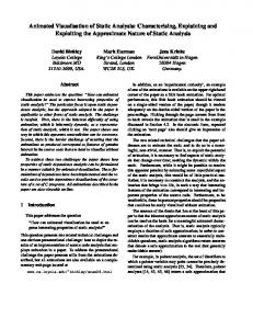
together to build a complete software product. The difference between component-based systems and more conventional software systems (e.g. using function libraries and class frameworks) is that component-based systems allow components to be "plugged" in at runtime, or unplugged and interchanged with other components. This supports user-configuration of systems, reusbility of components, and a more versatile and potentially robust "building block" approach to system architectures. Listen before/after changes sent by Comp1 Relationship Component
Component1
"change descriptions" sent from Comp1 to RelComp before and/or after change effected Listen before/after Comp2 receives changes from RelComp
Listen before/after changes sent by RelComp Component2
Component3
Figure 1. The JViews component-based architecture. JViews is a component-based software architecture we have been developing to support the construction of component-based design environments [10]. JViews exploits and extends the Java Beans componentware API of Java 1.1 [15]. The basic structure of a JViews component-based system is illustrated in Figure 1. Components (rectangles) are linked by relationship components (ovals) or simple reference links (solid lines). When a component undergoes a state change, it sends a "change description" object describing this change to "interested" linked components and relationship components. Interested components can choose to listen before and/or after the state change
occurs, or can even listen when other components receive change description objects. Change descriptions can be stored and used to implement a wide range of system functionality, including undo/redo for diagrams, attribute recalculation and constraint enforcement, versioning and collaborative editing [8]. JViews-based environments also support multiple views of work artefacts via "view relationships" between repository components and view components. View components are rendered in graphical or textual forms, and provide appropriate editing functionality. Figure 2 shows two examples of JViews-based environments in use. The view on the left hand side is from JComposer, a JViews-implemented CASE and meta-CASE tool. New JViews-based systems are specified in JComposer using an adaption of the notation in Figure 1, and JViews-based implementations of these tools are generated. The view shown on the right hand side is from the Serendipity-II process modelling environment. The Serendipity-II process model view shows stages in a software process, enactment event flows between stages, and start and end stages of this simple process model [12]. When designing and implementing a componentbased system, developers need to specify and visualise: • the components that make up such systems (i.e. name, attributes, methods). Users should be able to selectively show, hide, define, modify and delete such components and their basic characteristics. • the inter-component structure i.e. how the components are "wired" together to build a software system, and how methods in one component utilise methods in others.
Figure 2. An example of JComposer and a JComposer-generated environment.
•
the flow of events between components, as one characteristic of component-based systems is their strongly event-based nature [11]. This includes seeing when component-generated events are propagated and the nature of these events. • the way events propagated to a component are handled i.e. acted upon by the receiving component. This may be coded in a low-level programming language or specified using higherlevel constructs. Similar issues arise when trying to visualise running component-based systems. Visualisation of running systems is often desired by users and/or developers, in order to determine how such systems work, to locate and correct errors, and possibly to extend the running system by adding, removing or modifying components. Users of such systems are likely to want to be able to visualise: • running component states i.e. attribute values and component structural interconnections. Users may even want the ability to modify such running component states, including being able to create and link in new components. • event propagation between running components, to monitor how they behave. • event-handling of running components, and be able to modify this in limited ways, to dynamically change the behaviour of the system. • queries on the component structures that make up the system, with running component instances visualised using these query structures.
Our experiences with component-based software architectures has indicated that utilising similar, if not the same, notations to visualise static and dynamic aspects of such systems is preferred by users of these visualisations [11]. In the following sections we show how we have addressed some of the above issues for component-based systems utilising the JViews software architecture.
3. Static Structure Visualisation In order to facilitate the specification and static visualisation of JViews-based software architectures, we developed a visual Architecture Description Language (ADL) for the JViews architecture. This ADL evolved from earlier work with event-based software architectures, and is a unification of these ideas in the domain of component-based systems [9]. Figure 3 illustrates the basic components of this ADL for specifying in several views different aspects of the Serendipity-II environment. JComposer uses the same notation as introduced for JViews in Figure 1: rectangles represent components; ovals relationship components; and arrowed lines with name and arity represent intercomponent links. Some links indicate aggregation of several component instances by another component. Component specifications contain a name, superclass and some attributes and methods of the component. The user of JComposer can selectively hide or show component attributes and methods.
Figure 3. Specifying and navigating static component structures in JComposer.
The front view in Figure 3 (also shown in Figure 2) uses this notation to describe the basic Serendipity-II repository components, including a "base layer" (i.e. repository) component, process model stage components, a hashtable relationship linking stages to the repository component, and event flow components, which link stages in the process model. Such static visualisations are created by users of JComposer either interactively adding component and relationship specifications in views, or expanding existing components from the JComposer repository into views. Pop-up menus are used to facilitate navigation between views, specifying component information, adding, modifying and deleting attributes and methods, and creating new views. An important part of JViews-based (and componentbased systems in general) is the propagation of events between components. JViews uses the structural intercomponent links and relationship components as event propagation paths. Only specified links are used in this fashion, however, and links are annotated (if the user so requests) to indicate the kind of event propagation. JViews allows connected components to listen before and after events are actioned by the propagating component, and also allows components to listen before and after propagated events are actioned by a receiving component. We call this event "listening" and "handling" respectively.
Figure 4. Event propagation annoataions.
These additional link characteristics are visualised in JComposer views via appropriate annotation of link labels, as shown in Figure 4. We indicate such event dependency between components with lb ("listen before"), la ("listen after"), hb ("handle before"), ha ("handle after"), and agg ("aggregate") annotations. We tried using extra iconic annotations, as we used in the ViTABaL event-based ADL [7], but this became unwieldy. Users may visualise intercomponent event dependency and aggregation using these annotations, but specify such behaviour for a tool under design in
JComposer using a dialogue box. The dialogue box in Figure 4 is used to configure dependencies between the repository component and base stages relationship component. In this example, the repository component is sent events from the hashtable component after they occur and the hashtable aggregates linked base stages with the repository (hence the "(la, agg)" annotation). The hashtable relationship is sent base stage component events both before and after these are actioned, so it can check base stages have unique IDs and that if stages IDs are changed, the hashtable key is updated. The event flow component is sent base stage events after they have been actioned by the generating base stage component, so it can enact the base stage linked to it by the "inEvent" link.
4. Static Event Handling Visualisation In addition to visualising static component-based system structure and event propagation, there is a need to visualise how received events are handled by receiving components. Most component-based systems and tools require low-level programmatic coding of such behaviour. In our experience, such low-level handling of received events is difficult to visualise in a manner that assists users and developers of component-based systems to understand their behaviour. We have developed a complementary visual notation in JComposer for JViews-based systems which uses a simple, visual "filter" and "action" model of event processing. This language consists of reusable "filter" components which pattern match events or sequences of events of interest, and "action" components, which on receiving an event carry out some specified processing. This language is based on an earlier event handling language we developed for a predecessor of SerendipityII [12, 13]. While it does not completely replace the need for textually-coded event responses, it does allow both novice and experienced users of JViews-based systems to readily visualise and understand event handling. Figure 5 shows this language being used to statically specify an event handler for the Serendipity-II process modelling tool under construction. The user has connected action components (shaded ovals) to the hashtable and base event flow components. The "EnsureUniqueNames" action component listens before changes are made to the hashtable, with change events flowing into the top entry point of this action, defined in the right hand view. If the change is the addition of a new base stage (EstablishRel), or the change to a base stage ID (the hashtable key), the corresponding filters (square icons) checking for theis passes the event to the "NonUnique" filter.
Figure 5. Visualising event handling using JComposer filters and actions. This queries the hashtable to ensure the new base stage component ID is unique. If not, the change is rejected by passing the event onto the "NotifyError" and the "AbortOperation" actions. If the ID is unique the event is passed to the “Change Ok” exit point. The "EnactStage" action, attached to the BaseEventFlow component, handles events sent to the enactment flow component from base stage components. This action determines if a base stage has been completed, and if so it enacts the base stage linked to the enactment flow component by the "inEvent" link. Lowlevel filters and actions have their functionality programmed in Java, but may be reused via the visual filter and action language in many places in a JViewsbased system as required.
We use a slightly modified form of the JComposer notation, where component "IDs" are shown in place of the component name, and the type (component class) is shown in place of the superclass name. All links are shown as ovals ("relationship components" in JComposer). As links may be one-to-many, using this approach allows JVisualise to show only some dynamic link instances and allows users to interact with links. Relationship, filter and action components can be visualised using their JComposer notation (oval, rectangle, shaded oval respectively) or using the component icon so their attribute values can be viewed.
5. Dynamic Structure Visualisation When using a component-based system implemented using JViews there is often a need to visualise running components. For example, the developer of a system may wish to observe the system in use for debugging purposes, a user may wish to query a tool repository to locate particular components, or the user may wish to extend the functionality of the environment. We have developed the JVisualise tool which, for any JViews-based system, allows users of the system to visualise running JViews component structures. JVisualise uses a similar notation to the static JComposer ADL illustrated in previous sections. Figure 6 shows a Serendipity-II process model view (left hand view) being visualised using JVisualise (right hand view). In this dynamic visualisation the view component itself is shown at the top, with three view components (the "p1" and "p2" process stages and the event flow which links them). Some of the attributes of these components have been displayed, along with the "Parent" and "Child" links between the event flow "arrow" and the stage "icons".
Figure 6. Visualising components using JVisualise. To construct such dynamic visualisations, the user of JVisualise first specifies which initial JViews component they want added to a new or existing JVisualise view, via a pop-up menu item in any JViews view. The component is initially visualised showing only its ID and class name, and the user can then interact with this visualisation using a pop-up menu to specify attribute values to show, links to expand, etc. A simple automatic layout algorithm places visualised components, but users can then interactive move components to produce visualisations that best fit their cognitive model of the system. The composition and layout of dynamic visualisations can also be saved as "templates", and reused to visualise
different component instances with the same structure. Users reload a saved visualisation structure and indicate which running component they want the first visualised component replaced by. The other components in the visualisation are then updated to reflect the actual running state of the newly visualised system. Any links and components which no longer match actual running components are drawn in pale grey. JVisualise dynamic visualisations change when any component's attribute values change, or one of the visualised components or links is deleted. Users can also specify they want links highlighted when change descriptions are propagated between the components being visualised, to aid in debugging and understanding event flow in a JViews system.
Figure 7. User enhancement of a JViews-based system. Users of JVisualise can extend the visualised component structures by creating and linking components into the visualisation themselves. This permits end-user enhancement of environments, again utilising a similar notation to that of JComposer. For example, figure 7 shows another visualisation of the Serendipity model of Figure 6. The user has specified additional filter and action component instances by interactively adding them to visualised JViews components which have been interactively expanded into the view. When a component visualisation is interactively added in this way, JVisualise attempts to create a new instance of the component. When components are joined by links interactively by the user, JVisualise attempts to establish relationships between the running, visualised components. In Figure 7, the new filters and actions the user has created specify that when the “p1” process stage icon is modified, the user is informed by highlighting the icon in the view. The change description (modification event) generated indicating the change is also stored in a “version record” component. The latter is used to provide a dialogue box for viewing a history of changes. The user can interact with the newly created components in the same manner as ones which have been expanded into the view, to visualise them in other views, connect them to other components and so on. We have found the ability
of users of JViews-based environments to dynamically modify the state of a running system via our dynamic JVisualise tool, especially to add additional event handling behaviour, greatly enhances the power of users to tailor systems to the individual needs. Using a similar notation to the static visualisations in JComposer also allows users to work with models of a running system they are familiar with.
6. Dynamic Structure-based Querying The dynamic visualisations in the previous section are produced under tight user control; users incrementally extend the visualisation of a JViews component via popup menus and direct manipulation until they gain a satisfactory visualisation of a group of running component structures. Users may also specify multiple visualisations of containing common structures as required. However, while this approach is useful for localised component structures, we have found it poor for large collections of components, such as the repositories of Serendipity-II and JComposer-style tools. To allow users to better construct appropriate visualisations in such situations, we have incorporated a visual query component into JVisualise. Figure 8 shows a JVisualise visual query applied to the Serendipity-II repository to select all process model stages which have an output event flow named "finished". We use the JVisualise notation to formulate this query, constructed by direct manipulation. Instead of showing particular dynamic component and link instances, this query is run to link component and link icons to component instances and links in the Serendipity-II repository matchinf the query constraints. In this example, the user has specified they want any base stage component which is linked to an event flow named "finished". Users specify optional links to match (0:1 or 0:n), AND/OR conditions, and attribute names to be shown in the result. When such queries are run, JVisualise locates all components which match those specified in the query. These are not all displayed at once, however, as a great many components and links may match a query. Instead, an exact copy of the query visualisation is made , which is used to display the query result. The first component matching the first component specification in the query is visualised, with other matching components (if any) added to a pop-up menu item for the component icon in the query result. For each component specification linked to this first component visualised, the first matching component in this "subquery" is visualised, with other components matched added to pop-up menus. The user may then successively select differently-matched component instances for each component icon in the query result, viewing different subquery results as they do so. This is illustrated in Figure 8. One base stage
matches the query, and it is visualised in the query result by linking the query view icons to the matching component instances. If more than one base stage were matched, the user can select other matches via the popup menu item. Instances of the event flow component and the base stage linked to the event flow by the "inEvent" link change if the user selects a different base stage.
prebuilt components in an appropriate manner. They do not however provide visual event-handling configuration. Visual query languages have been developed for both database and CASE tool repository inspection. Examples include graphical querying of ER models [4, 20], and CASE tool repository querying [17, 1]. Such approaches to visual querying usually attempt to fully formulate queries visually [17, 4], but often present results in a conventional textual manner. We took the approach of allowing users to use the JVisualise notation for queries, with component structures queried visually but attribute constraints done textually. We have found this more convenient to use for end-users than (often cumbersome) fully visual query languages. We also use the visual query structure to present the results of the query to users, which provides a more easily navigated visualisation of matching software components than textual output. An alternative would be to visualise ALL matching software components, resulting in potentially very large component interconnection graphs. While various approaches exist to visualise such output [2, 5], we have found the use of the JVisualise queries most useful in our application domain. Other event-based software system visualisation techniques include those of ViTABaL [7], Zhang et al [23, 19], and Wirtz [22], and those of dataflow languages, such as Prograph [3]. We have found the use of simple annotation techniques in JComposer to be less cumbersome and cluttered than visual annotations. The visualisation of running component event propagation is currently simplistic in JVisualise, but can be straightforwardly enhanced by filters and actions. 8.
Figure 8. A dynamic JVisualise component query. 7.
Discussion
Many systems have been developed which attempt to provide static and dynamic visualisations of event-based and/or component-based systems. For example, VisualAge for Java [16] and Jbuilder [24] provide limited Java Beans component static visualisation capabilities to support the generation of Java Beans classes. Similarly, ClockWorks [6] provides a tool for specifying and generating Clock components. Such tools do not generally provide a range of different kinds of component visualisations, such as JComposer's filters, actions and relationship components. Dynamic visualisation of component-based systems are often used to allow end-users to configure such systems themselves. Examples include BeanMachine [14], MET++ [21], and VisualJavaScript [18]. These systems allow users to compose systems by combining
Summary
We have described a variety of novel static and dynamic visualisation techniques for component-based software systems. Developers of such systems need facilities to statically specify the components, component interconnections and event handling of such systems. Our JComposer tool provides for systems utilising the JViews component-based software architecture. JVisualise provides dynamic visualisation capabilities for JViewsbased systems, including component inspection, component interconnection visualisation, event handling enhancement and visual querying of JViews component structures. We are enhancing JComposer and JVisualise with additional notation, for example distinguishing between reused and built-from-scratch components, inherited and user-specified component interconnections, and allowing change description events to be visually displayed on diagrams. We are also adding method calling links to our notation to allow intercomponent method calls to be distinguished from event propagation. These enhancements will allow developers to more easily
understand complex aspects of component-based systems with significant numbers of reused components and disparate change descriptions being propagated. We are also investigating the use of improved automatic layout algorithms for JVisualise views, and the use of large graph structure visualisation using VR techniques to assist in understanding of very large component-based software. References [1]
Bird, B., “An Open Systems SEE Query Language,” in Proc. of 7th Conference on Software Engineering Environments, IEEE CS Press, Netherlands, 1995. [2] Consens, M., Medelzon, A., and Ryman, A., “Visualising and querying software structures,” in Proc. 14th International Conference on Software Engineering, IEEE CS Press, Australia, May 1992. [3] Cox, P.T., Giles, F.R., and Pietrzykowski, T., “Prograph: a step towards liberating programming from textual conditioning, , IEEE Computer Society Press,” in Proc. 1989 IEEE Workshop on Visual Languages, 1989, pp. 150-156. [4] Czejdo, B., Elmasri, R., Rusinkiewicz, M., and Embley, D.W., “A Graphical Data Manipulation Language for an Extended Entity-Relationship Model,” COMPUTER, vol. 23, no. 3, 26-36, 1990. [5] Eades, P. and Feng, Q., “Drawing very large graphs using clustering,” in Proc. 1997 Workhop on Software Visualisation, Department of Computer Science, Flinders University, Australia, Dec 1997. [6] Graham, T.C.N., Morton, C.A., and Urnes, T., “ClockWorks: Visual Programming of ComponentBased Software Architecture,” Journal of Visual Languages and Computing, 175-19, July 1996. [7] Grundy, J.C. and Hosking, J.G., “ViTABaL: A Visual Language Supporting Design By Tool Abstraction,” in Proc. 1995 IEEE Symposium on Visual Languages, IEEE CS Press, Darmsdart, Germany, September 1995, pp. 5360. [8] Grundy, J.C., Venable, J.R., Hosking, J.G., and Mugridge, W.B., “Coordinating collaborative work in an integrated Information Systems engineering environment,” in Proc. 7th Workshop on the Next Generation of CASE tools, Crete, 20-21 May 1996. [9] Grundy, J.C., Hosking, J.G., and Mugridge, W.B., “Towards a Unified Event-based Software Architecture,” in Proc. SIGSOFT'96 Workshops, ACM Press, October 14-15 1996, pp. 121-125. [10] Grundy, J.C., Mugridge, W.B., and Hosking, J.G., “A Java-based toolkit for the construction of multi-view editing systems,” in Proc. Second Component Users Conference, Munich, Germany, July 1997. [11] Grundy, J.C., Hosking, J.G., and Mugridge, W.B., “Visualising Event-based Software Systems: Issues and Experiences,” in Proceedings of SoftVis'97, Dept. of Computer Science, Flinders University, Australia, December 11-12 1997. [12] Grundy, J.C. and Hosking, J.G., “Serendipity: integrated environment support for process modelling, enactment Automated Software and work coordination,” Engineering, vol 5, no 1, 1998.
[13] Grundy, J.C., Hosking, J.G., and Mugridge, W.B., “Support for end user specification of workflows, work coordination and tool integration,” Journal of End User Computing, vol. 10, no. 2, May, 1998. BeanMachine™, [14] Lotus Lotus`Inc., http://www.lotus.com/beanmachine, 1997. [15] Java Beans 1.0 Specification, Sun Microssystems Inc, http://www.javasoft.com/beans/, 1996. Visual Age for Java™, [16] IBM IBM, http://www.software.ibm.com/ad/vajava, 1997. [17] Liu, H., “A Visual Interface for Querying a CASE Repository,” in Proc. 1995 IEEE Symposium on Visual Languages, IEEE CS Press, 1995, pp. 21-28. [18] Netscape Visual JavaScript™, Netscape`Inc., http://www.netscape.com/compprod/products/, 1998. [19] Stankovic, N. and Zhnag, K., “Graphical composition of messgae-passing programs,” in Proc. 1997 Workshop on Software Visualisation, Department of Computer Science, Flinders University, Australia, Dec 11-12 1997. [20] Teorey, T.J., Yang, D., and Fry, J.P., “A Logical Design Methodology for Relational Databases Using the Computing Extended Entity-Relationship Model,” Surveys, vol. 18, no. 2, 197-222, 1986. [21] Wagner, B., Sluijmers, I., Eichelberg, D., and Ackerman, P., “Black-box Reuse within Frameworks Based on Visual Programming,” in Proc. 1st Component Users Conference, SIGS Books, 1997. [22] Wirtz, G., “A Visual Approach for Developing, Understanding and Analyzing Parallel Programs,” in Proc. 1993 IEEE Symposium on Visual Languages, IEEE CS Press, 1993, pp. 261-266. [23] Zhang, D.Q. and Zhang, K., “A Visual Programming Environment for Distributed Systems,” in Proc. 1995 IEEE Symposium on Visual Languages, IEEE CS Press, Darmsdadt, Germany, 1995. JBuilder™, [24] Borland Borland Inc., http://www.borland.com/jbuilder, 1997.