May 14, 2006 - Status Report: Towards Shape-Changing Robots. David Johan Christensen. The Maersk Mc-Kinney Moller Institute for Production Technology.
Status Report: Towards Shape-Changing Robots
David Johan Christensen The Maersk Mc-Kinney Moller Institute for Production Technology University of Southern Denmark May 14, 2006
2
Abstract This topic of this status report described the author’s progress towards the realization of shape-changing robot. The majority of the work circles around the control of a particular selfreconfigurable robot, the ATRON. The developed control strategy is based on meta-modules that move on the surface of other modules. The idea is that by controlling the flow of meta-modules from one position to another the desired shape-change can be realized. This control strategy is shown to be able to control the shape-change of large groups of ATRON modules in a both failure tolerant and scalable way. Inspired by the problem of assembling complex functionality robots from a large number of modules, we then define a series of biological inspired functional building blocks. The building blocks which are assembled from ATRON modules have functionality inspired by bone, neuron, muscle and joints. The idea is, and future work will explore this, to assemble functional robots using such building blocks assembled from miniaturized modules. We also define the concept of a novel class of shape-changing robots: ”Robotic Deformable Sheets”. The idea is to have 2D surfaces of a robotic material which folds and deforms into 3D shapes. The main difference from self-reconfigurable robots is an expected simpler hardware realization and a faster shape-change. We describe some initial steps towards realization of such a system.
3
4
Preface This status report documents the research I have done during my first two years as a Ph.D.-student at the Maersk Mc-Kinney Moller Institute for Production Technology, University of Southern Denmark. It described the results achieved so far and future lines of research for the remaining two years. The topic of my work is self-reconfigurable robots, in particular the ATRON system, developed at the Maersk Institute.
David Johan Christensen, May, 2006
5
6
Contents 1 Introduction 1.1 What is a Self-Reconfigurable Robot? . . . . 1.2 Why Study Self-Reconfigurable Robots? . . . 1.3 A Brief History of Self-Reconfigurable Robots 1.4 Taxonomy of Self-Reconfigurable Robots . . .
. . . .
. . . .
. . . .
. . . .
. . . .
. . . .
. . . .
. . . .
. . . .
. . . .
. . . .
9 9 9 10 10
2 Related Work 2.1 Systems and Control for Self-Reconfiguration 2.1.1 Chain Type . . . . . . . . . . . . . . . 2.1.2 2D Lattice Type . . . . . . . . . . . . 2.1.3 3D Lattice Type . . . . . . . . . . . . 2.1.4 3D Hybrid Type . . . . . . . . . . . . 2.1.5 Abstract Proposed Types . . . . . . . 2.2 Alternative Ways to Self-Assemble . . . . . . 2.2.1 Swarm Robots . . . . . . . . . . . . . 2.2.2 Stochastic Self-Assembly . . . . . . . . 2.2.3 Fluid Modules . . . . . . . . . . . . . 2.2.4 Biological Inspired Morphogenesis . . 2.2.5 Physical Self-Reproduction . . . . . .
. . . . . . . . . . . .
. . . . . . . . . . . .
. . . . . . . . . . . .
. . . . . . . . . . . .
. . . . . . . . . . . .
. . . . . . . . . . . .
. . . . . . . . . . . .
. . . . . . . . . . . .
. . . . . . . . . . . .
. . . . . . . . . . . .
. . . . . . . . . . . .
13 13 13 15 17 19 20 22 22 22 22 23 23
3 ATRON Self-Reconfigurable Robotic 3.1 Design of the ATRON Module . . . 3.2 Application Versatility of ATRON . 3.3 Related Work On ATRON Control .
System 25 . . . . . . . . . . . . . . . . 25 . . . . . . . . . . . . . . . . 27 . . . . . . . . . . . . . . . . 28
4 Control of ATRON Using Meta-Modules 4.1 Introduction . . . . . . . . . . . . . . . . . . . . . . 4.2 The Meta-Module Control Strategy . . . . . . . . . 4.2.1 What is a Meta-Module? . . . . . . . . . . 4.2.2 Meta-Module Life-Cycle . . . . . . . . . . . 4.2.3 Attraction-points as Task Specification . . . 4.2.4 Reachable Space of Meta-Modules . . . . . 4.3 Selecting a Meta-Module Type . . . . . . . . . . . 4.3.1 Small and Non Lattice-based Meta-Modules 7
. . . . . . . .
. . . . . . . .
. . . . . . . .
. . . . . . . .
. . . . . . . .
. . . . . . . .
. . . . . . . .
. . . . . . . .
31 31 32 32 32 33 34 34 34
8
CONTENTS
4.4
4.5
4.6 4.7
4.3.2 Different Meta-Modules Types . . . . 4.3.3 Characteristics of Meta-Module Types 4.3.4 Results and Conclusion . . . . . . . . Evolving Control for Meta-Module . . . . . . 4.4.1 The Selected Meta-Module Type . . . 4.4.2 Artificial Neural Network Controller . 4.4.3 Evolution of Artificial Neural Network Experiments . . . . . . . . . . . . . . . . . . . 4.5.1 Shape-Change and Self-Repair . . . . 4.5.2 Scalability and Failure Tolerance . . . 4.5.3 Physical Meta-Modules . . . . . . . . Discussion . . . . . . . . . . . . . . . . . . . . Conclusion and Future Work . . . . . . . . .
. . . . . . . . . . . . . . . . . . . . . . . . . . . . . . . . . . . . Controller . . . . . . . . . . . . . . . . . . . . . . . . . . . . . . . . . . . .
. . . . . . . . . . . . .
. . . . . . . . . . . . .
. . . . . . . . . . . . .
. . . . . . . . . . . . .
. . . . . . . . . . . . .
35 38 42 42 42 43 46 47 47 49 54 59 59
5 Building Blocks From Micro ATRON Modules 5.1 Motivation . . . . . . . . . . . . . . . . . . . . . 5.2 Why Size Matters! . . . . . . . . . . . . . . . . . 5.2.1 Connector Strength . . . . . . . . . . . . 5.2.2 Speed of Self-Reconfiguration . . . . . . . 5.3 Biological Inspired Building Blocks . . . . . . . . 5.3.1 Bone . . . . . . . . . . . . . . . . . . . . . 5.3.2 Neuron . . . . . . . . . . . . . . . . . . . 5.3.3 Muscle . . . . . . . . . . . . . . . . . . . . 5.3.4 Joint . . . . . . . . . . . . . . . . . . . . . 5.3.5 Other considerations . . . . . . . . . . . . 5.4 Discussion, Summary and Future Work . . . . .
. . . . . . . . . . .
. . . . . . . . . . .
. . . . . . . . . . .
. . . . . . . . . . .
. . . . . . . . . . .
. . . . . . . . . . .
. . . . . . . . . . .
. . . . . . . . . . .
. . . . . . . . . . .
61 61 61 62 63 64 64 65 65 67 68 68
6 Discussion and Future work 6.1 Future Challenges of Shape-Changing Robots 6.2 Redesigning the ATRON Hardware . . . . . . 6.3 Three degree of freedom ATRON modules . . 6.4 Robotic Deformable Sheets . . . . . . . . . . 6.4.1 The concept . . . . . . . . . . . . . . . 6.4.2 Design Considerations . . . . . . . . . 6.4.3 Towards implementation . . . . . . . . 6.4.4 Summary and Future work . . . . . .
. . . . . . . .
. . . . . . . .
. . . . . . . .
. . . . . . . .
. . . . . . . .
. . . . . . . .
. . . . . . . .
. . . . . . . .
. . . . . . . .
71 71 72 73 75 75 76 78 78
. . . . . . . .
. . . . . . . .
7 Conclusion
81
A Publication List
99
Chapter 1
Introduction 1.1
What is a Self-Reconfigurable Robot?
The concept of self-reconfigurable robots were introduced in [32] by Fukuda and Nakagawa, they define that a self-reconfigurable robot: Consists of several cells (or modules), each cell have some measure of intelligence and the cells can automatically be combined and detached. Today most self-reconfigurable robot systems, consist of a number of interconnected mechanical robot modules. Modules have their own computational power and are able to communicate with other modules and sense the environment. The modules have connector and actuated degrees of freedom that allow them to connect to, disconnect from and move relative to other modules in order to change the configuration of modules without human intervention. The design of the modules provide the self-reconfigurable robot with abilities such as shape-change to optimal configuration in a given situation and failure tolerance from redundancy and ability to self-repair.
1.2
Why Study Self-Reconfigurable Robots?
The reasons for studying self-reconfigurable robots are at least two-fold. On one side the exploration of such systems may provide insight into the nature and principles of biological organisms: To understand biology we must understand its basic principles such as modularity, redundancy, emergence, selforganization and self-replication. On the other side a strong reason for studying self-reconfigurable robots may be its possible applications. Potential short term areas of applications include exploration of unknown and hazardous environments such as space or earth-quake areas, entertainment such as art or toys and production such as flexible robot arms. On the long term applications also include three dimensional physical screens and remote physical presence. The two reasons for studying self-reconfigurable robots are by no means exclusive. A strong focus on the basic research of biological principles will in time reveal new possibilities and open new doors for applications. On the other hand a focus 9
10
CHAPTER 1. INTRODUCTION
on applications will force real life constraints onto the otherwise abstract theory and much experience can be transferred to theory by working with real world problems. The study conducted in this thesis is a compromise between the two extremes. The studies conducted are not far from possible applications, while at the same time contains a more fundamental scientific value.
1.3
A Brief History of Self-Reconfigurable Robots
The idea and fascination of building artificial creatures has been around for as long as humans. Drawings on the walls of caves and figures carved in wood or amber is amongst the earliest examples. Historically new technology and insight has served as inspiration for the creation of artificial creatures. In the mid-19th century the new found understanding of biological cells and genetics stimulated the development of new types of artificial creatures. John Von Neumann founded the field of Cellular Automata, when he in 1950 described self-reproducing automata [79]. Later mechanical prototypes for self-assembly and self-replication were developed, for example Penrose’s wooden bricks from 1957 [88, 89]. With biological cells as a clear source of inspiration, Fukuda and Nakagawa in 1988 described the concept of ”Dynamically Reconfigurable Robotic System” [32]. They proposed that this type of robot system should consist of ”several cells”, each cells should have some ”intelligence” and the cells should be able to ”be combined and detached by one another automatically”. Compare to traditional robots they claimed that the advantages were amongst other: optimal shape under circumstances, fault tolerance and self repair. Fukuda et al. also reported the first implementation of a self-reconfigurable robot, the cell structured robot (CEBOT) [27, 34, 35], which is briefly described in section 2.1.3. Before that some similar systems had been proposed but they had never reached past the conceptual level. Since this first self-reconfigurable modular robotic system, about twenty such systems have been constructed. Some of these systems are reviewed in chapter 2. Today the field is still gathering momentum and new system are being constructed: The ATRON, SuperBot and Catom systems are examples of new systems. Some systems, such as Superbot, are designed with a focus on space or inspection, taking self-reconfigurable towards applications. While other systems, such as the Catom, focus on micro-scale modules in great numbers which brings the system closer to the original source of inspiration: the biological cell.
1.4
Taxonomy of Self-Reconfigurable Robots
Self-reconfigurable modular robotic systems are classified by properties of the module type(s) comprising the system, by the characteristics of interconnected modules and by the control strategy applied to the system. This section presents some of the most commonly used distinctions used for classifying self-reconfigurable robots.
1.4. TAXONOMY OF SELF-RECONFIGURABLE ROBOTS
11
Homogeneous vs. Heterogeneous A system may be homogeneous in hardware and/or in control. If only one module type exist in the system the hardware is homogeneous, if more than one it is heterogeneous. Most selfreconfigurable robots today consist of only one or two module types. The reason is probably that the system becomes simpler to design on the conceptual level and modules cheaper to mass produce. However it might very well be the case that some desirable robot behaviors can not be achieved using only one module type. Lattice vs. Chain Based On way to categorize different self-reconfigurable robotic systems is by dividing them into lattice or chain based systems. In lattice-based system the modules are positioned and move within a lattice like the atoms of a crystal. The lattice facilitates self-reconfiguration, since it helps to align connectors on neighbor modules. In chain based systems the modules are positioned in a chain that may branch and contain loops. The chain based approach can be more easily applied to real world problem such as locomotion. Some system can be categorized as hybrids since they can function both as chain and in lattice configurations, the M-TRAN, ATRON and SuperBot are examples of such systems. Centralized vs. Distributed Control Control for self-reconfiguration may be centralized, where the actions of the individual modules are organized from a central computer or human with a plan. Or it may be distributed control where the modules themselves select their actions based on local conditions, and the collective behavior emerges. The pros of distributed control is that it seems to facilitate scalability and fault-tolerance while centralized control is provable, closer to optimal and easier to design. Static (hard-coded) control is useless in most applications; it is however the way most physical self-reconfigurable robots are controlled today. Degree of Freedom To do actual work on the environment and to self-reconfigure modules must be actuated. The degree of freedom of each module, affects the complexity of controlling and constructing the system. The actuated degrees of freedom are usually rotational or linear. Connector Mechanism The connector system is crucial for supporting selfreconfiguration and is one of the most channelling mechanical parts in such a system. Connector systems can be categorized into unisex or male/female types. They can also be categorized by their technology: mechanical, magnetic, electro static, etc. Important aspects of connectors include their strength, rigidity, alignment tolerances and whether or not they need energy to connect/disconnect and stay connected. Energy The means of energy supply affects the autonomy of the individual modules and the system as a whole. Some modular systems are powered externally through wire, while other systems gets their energy from onboard batteries. Power-sharing between modules is an important feature not yet implemented in many systems.
12
CHAPTER 1. INTRODUCTION
Communication Communication are needed to coordinated the actions of the modules. Direct communication may be divided into global or local. Global, broad-cast types, communications has the problem that it does not scale well with the number of modules. The local alternative is neighbor to neighbor communication, which has a problem with communication speed in system with many modules, since the message must pass through many modules to reach its target. In some control work stigmergy (emergent communication through the environment), is as important as direct communication.
Chapter 2
Related Work This chapter first briefly describes a number of different self-reconfigurable robotic systems and some of the control strategies developed to control them. The systems are grouped into Chain, 2D lattice, 3D lattice and Hybrid systems. Then alternative ways to self-assemble, other than self-reconfiguration, are described.
2.1 2.1.1
Systems and Control for Self-Reconfiguration Chain Type
Polypod The first chain based self-reconfigurable robot, Polypod, was developed by Yim [134, 135] as part of his Ph.D work in the early 90’s. It consist of two module types: Segments and nodes. Segments have two degree of freedom (DOF) and are equipped with actuation, sensing, computation and communication. Node modules have batteries and six connectors to allow chains in the robots. Unisex connectors, that passively connect and disconnect using a shape memory alloy (SMA), allow the Polypod to self-reconfigure. The main ability of the Polypod is locomotion, such as snakes, walkers and rolling tracks [134, 136] and autonomous shifting between different locomotion styles, figure 2.1(a) shows the Polypod segment. Different locomotion styles is controlled using gait control tables, which defines the action of each module in a given global time-step. Polybot The Polybot [139] is a second generation of Yim’s Polypod. Polybot also consist of nodes and segments but the mechanical complexity of segments have been decreased. Polybot segments only have a single rotational degree of freedom, see figure 2.1(b). Since the late 90’s three generations of the Polybot system has been developed [23]. The later versions (not the first) are able to self-reconfigure and most of the versions use external power. It is more difficult to self-reconfigure chain than lattice based systems, since the lattice helps aligning connectors. On the Polybot, IR emitting and sensing are used to 13
14
CHAPTER 2. RELATED WORK
(a)
(b)
(c)
Figure 2.1: (a) Polypod segments. (b) Polybot segment. (c) Conro module. align the unisex connectors [93, 146]. As for the Polypod, the Polybot is able to perform many different types of locomotion [138, 141] and also surface-based distributed manipulation has been shown [143]. Locomotion is controlled using phase automata patterns [155], that is state machine, defining the actions of a module in a given state. The shift from one state to another is event (time or sensor) driven. Proposed applications for the Polybot include manipulation and locomotion in space [144], urban search and rescue [137] and land warfare [25]. Conro The Conro system [15–17] consist of homogenous modules, see figure 2.1(c). The modules are self-contained including batteries. Each module has two rotational DOF (yaw and pitch). A module has one female and three male connectors, which allows snake, tree or single loop configurations. In its latest version the female connector it is actively able to release the male connector [53, 54]. Automatic docking has been achieved [94, 101], as for the PolyBot, connectors are aligned using IR feedback for guidance. The Conro system is especially suited for different styles of locomotion. The rule-based control strategy was developed by Stoy in [108, 109, 111]. A role is automatically selected by each module dependent on its position in the configuration tree. This allows Conro robots to shift from one locomotion style to another when they are manually reconfigured [110]. First proposed by Shen et al. [98, 99] hormonebased control is a generic strategy which allow information to be distributed between the modules. Digital hormones represent information which propagates through the configuration of modules. Using digital hormones modules can detect topological changes, coordinate and synchronize actions for locomotion or self-reconfiguration [95, 100]. Self-Reconfiguration of Chain-Based Systems The natural approach to represent the configuration of a chain-based robot, is with a graph [18]. An distributed algorithm for discovery of topology changes were given by Salemi et al. in [96]. In [14], Casal and Yim divides reconfiguration into three different classes: Mobile (each module is mobile in the environment), Substrate (lattice based systems) and Closed chain (chain based systems) reconfiguration. For closed chain reconfiguration planning algorithms transforming one configura-
2.1. SYSTEMS AND CONTROL FOR SELF-RECONFIGURATION
(a)
(b)
15
(c)
Figure 2.2: (a) Workings of a Fracta unit. (b) Group of Fracta units. (c) Two micro-units. tion graph to another, and thereby the robot from one configuration to another. Such planning algorithms has been presented in [14] and [140]. The latter algorithm required O(log n) (n≤ number of modules) reconfiguration steps to transform any configuration to any other, which is optimal. However physics is not included in the planning trajectories, so the plans might be unfeasible.
2.1.2
2D Lattice Type
CEBOT The first self-reconfigurable robot were the cell structured robot (CEBOT), proposed and partly implemented from the late 80’s by Fukuda et al. [27, 34, 35]. The proposed system is heterogenous with three levels of module/cells types: 1) actuation and mobile cells, 2) branching, length adjustable, orientation changing and power cells, 3) Work cells, such as end-effectors. Different prototypes of different modules types have been developed. In [34] a mobile (wheeled) cell, with some sensing capabilities can dock to a passive object cell using infrared light for guidance. Communication between cells is explained in [31], and in [28] cells are assembled using robot arms. A number of studies is conducted on distributed control of the CEBOT, including how to organize distributed knowledge [33], how to organize groups behavior [29] and how to make distributed decisions [30, 52]. Fracta In 1994, Murata et al. presented the Fracta unit [76], see figure 2.2(a) and 2.2(b). Its simple and clever, design allowed it to rotate around any of its six neighbour units using tree electro-magnets. The hardware implementation includes computation and optical neighbor to neighbour communication, power is external. 20 modules were made. A simple random based selfreconfiguration/self-assembly strategy were presented in [76]. Based on local conditions a unit can estimate a distance to its goal, if the distance is not zero it will with some probability make a random move. In [154] the self-reconfiguration strategy is improved to avoid deadlocks and speeded up by moving in the direction more probable to be correct instead of just random. If units are removed from the system a process of self-repair begins. The system self-reconfigures so that spare units to take over the holes in the structure. This method works well
16
CHAPTER 2. RELATED WORK
(a)
(b)
(c)
Figure 2.3: (a) A single Crystalline Atom. (b) A group of Crystalline Atoms. (c) Two Catoms. for system with few units ( 50) the transitions that should be performed to change from one shape to another, is infeasible to define by hand. For such applications automated control strategies are necessary. Centralized control strategies have the problem that they generally do not scale well in terms of neither communication nor computation. Instead we use distributed control, where each module for itself decides what to do and when. The shape change of large groups of ATRON modules then emerge from the actions of the individual modules. There are hard motion constraints on the individual ATRON modules, mainly because they only have a single degree of freedom. This makes it highly complex to compute the sequence of actions the modules must perform to move a single ATRON module from one place to another in the configuration of modules. Actually such an sequence of actions can be very long and might not even exist. To overcome such motion-constraints, we use meta-modules that are able to move much more freely on the surface of other modules, than a single ATRON module. In this chapter we first introduce the meta-module based control strategy 31
32
CHAPTER 4. CONTROL OF ATRON USING META-MODULES
used. Then in section 4.2 we compare six different meta-module types composed of ATRON modules. Variations of meta-module morphology and meta-actions are investigated for its ability to shape-change the robot. We conclude that two of the investigated meta-module types are able to shape-change the robot to an acceptable extent and select one for further investigations. In section 4.4 we evolve an artificial neural network based controller for the most promising of the meta-module types. The controller is identical on every module and controls when a meta-module emerges, how it move and when it stops. Section 4.5.1 demonstrates how this evolved control strategy allows the ATRON robot to shape-change to support an unstable roof, build a bridge across a gap and to self-repair a broken bone. In section 4.5.2 we present experiments in simulation that verify that the evolved controller scales to thousands of modules. We also present experiments that show how different degrees of catastrophic module failure affect the robot’s ability to shape-change to support an insecure roof. We conclude that the robot show a graceful degradation of functionality when the number of module failures increase. Even at a module failure rate of 10% the robot is able to perform its function. Finally section 4.5.3 presents experiments with meta-module on the physical system. That demonstrates the basic functionality of meta-modules and shows how meta-modules can move around unknown obstacles and how multiple meta-modules can co-exist. The experiments work as a proof of concept, showing that the meta-module control strategy is indeed transferable to the physical modules.
4.2 4.2.1
The Meta-Module Control Strategy What is a Meta-Module?
A meta-module is composed of a number modules collaborating to achieve the common task - to move the meta-module. Seen from the outside a meta-module is considered a single acting entity or agent. We define a meta-module type by its morphology and the meta-actions it is able to perform: • Morphology: Meta-modules of a given type are composed of a specific number (one or several) of modules, which are interconnected in a specific way. • Meta-Actions: Meta-modules of a given type can perform a specific number of different meta-actions. Meta-actions are composed of a sequence of basic module actions, which are performed by the modules part of, or neighbour to, the meta-module. Basic module actions of the ATRON are rotation, connection and disconnection.
4.2.2
Meta-Module Life-Cycle
A meta-module starts its life by emerging from the structure of modules; that is, a module or group of modules agrees to form a meta-module. Then the metamodule starts performing a sequence of meta-actions, which result in movement
4.2. THE META-MODULE CONTROL STRATEGY
33
of the modules which comprise the meta-module. At some point the metamodule decides that it is time to stop and the modules become passive once again. This approach is similar to the division, migration and death of biological cells. The problem of self-reconfiguration is then to control the flow of meta-modules from one place to another on the structure of modules. In our implementation the life cycle of a meta-module consists of 3 phases: Emerge: Based on local information modules can decide to become a metamodule, if they are interconnected in a valid meta-module configuration. When they emerge the modules are no longer regarded as a part of the structure but as a living agent moving on the surface of the structure. Move: In this phase the meta-module moves on the surface of the structure modules, that is, the modules that are currently not part of a metamodule. Meta-modules are not allowed to move on other meta-modules as they might try to move themselves. The movement of meta-modules is based on attraction points which define the shape of the desired global configuration. The goal of the meta- module is to minimize its distance to an attraction point. Stop: At some point in time the meta-module might reach an attraction point or discover that it is not possible for it to do so. Then the meta-module will stop and the modules cease to collaborate. When stopped the modules are no longer regarded as a moving agent but as a part of the structure such that other meta-modules can move on its surface. This life cycle of the meta-modules can be repeated and the modules can at a later time again be part of a different meta-module. The local autonomous control based on attraction points makes it possible for a large number of metamodules to be active at any given time increasing the speed of the shape change.
4.2.3
Attraction-points as Task Specification
We use attraction-points to control the flow of meta-modules from one place to another on the structure of modules. Attraction-points are virtual points in space, whose positions are known to the modules. Meta-modules are attracted by attraction-points and move toward them if possible. Attraction-points are used to specify tasks for the self-reconfigurable robot. E.g. if the robot is to change its shape to meet some specifications this could be done by providing the robot with a set of attraction-points in the desired shape. Two types of attraction-points have been used in this work: inhibiting and non-inhibiting. An inhibiting attraction-point turns off if a module is placed at its position, then meta-modules are no longer attracted by that point. Non-inhibiting attractionpoints always attract meta-modules.
34
CHAPTER 4. CONTROL OF ATRON USING META-MODULES
4.2.4
Reachable Space of Meta-Modules
Any meta-module that emerges will be able to move in some well defined space on the structure of modules. From its starting state (position and orientation) it will be able to perform a finite number of meta-actions each of which may be legal or illegal (e.g. would result in collision between modules). A legal metaaction performed by the meta-module will change the state of the meta-module. If we assume the structure to be static, this will allow us to build a graph for each meta-module, having the meta-module states as vertices and meta-actions as edges. This graph will define the reachable space of the meta-module: • The reachable-space of a meta-module is a graph, where vertices are legal states (position and orientation) of the meta-module and edges are legal meta-actions which brings the meta-module from one legal state to another. In section 4.3 we use the reachable-space of meta-modules to measure some characteristics of the different meta-module types. In section 4.4 a local subset of a meta-module’s reachable-space is used to control it. Some example reachablespaces of different meta-module types is visualized in figure 4.3.
4.3
Selecting a Meta-Module Type
To find a meta-module type able to handle the hard motion constraints of the ATRON module we compare six different meta-module types in this section. The meta-module should be small, highly moveable, effective and efficient.
4.3.1
Small and Non Lattice-based Meta-Modules
None of the six meta-module types we investigate in this section are composed of more than 3 modules. It is possible to build larger meta-modules from, e.g., 12 modules, which have very good motion capabilities. Such meta-modules are positioned and move within a lattice of meta-modules. In this work we do not consider lattice-based meta-modules which are so large for a number of practical reasons: • Meta-modules that sit in a lattice increase the granularity of the system. • The increase in cost and complexity of a single meta-module (e.g. 12-DOF) can hardly be justified by the improved motion capabilities. • It would be impossible to do experiments with more than a few metamodules using the existing 100 prototypes of the ATRON modules. None of the above is true for the meta-modules explored in this work. In particular the meta-modules do not increase granularity (except meta-module type 6), because they emerge, move and stop. When stopped, the modules which were
4.3. SELECTING A META-MODULE TYPE
(a)
35
(b)
Figure 4.1: Difference between lattice-based meta-module types and metamodule types that emerge. (a) A two module meta-module could sit in a permanent 2D lattice as indicated. The meta-modules would move from one lattice position to another. This increases the system’s granularity. (b) In this work any combination of two connected modules may emerge as a meta-module. The meta-modules do not sit in any particular lattice and modules are free to be part of different meta-modules at different times, therefore granularity does not increase.
part of a meta-module may at a later time become part of a different metamodule which is not necessarily composed of the same modules, as illustrated in figure 4.1.
4.3.2
Different Meta-Modules Types
We compare six different meta-modules types, differentiated by their morphology and meta-actions. The meta-modules are referred to as meta-module type 1 – 6. The number of modules in the meta-module types and the number of meta-actions is summarized in table 4.1. The three different meta-module types’ morphologies, shown in figure 4.2(b)-(c), are selected so that they can often emerge from unstructured groups of modules. The meta-actions for type 1, 2, 3 and 4 are designed by taking direct inspiration from the morphology of the meta-modules. Meta-module types 5 and 6 expand type 4. The expansions come from experience gained by investigations of type 4. The morphology and meta-actions of the six different meta-module types are explained below. Examples of reachable spaces for meta-module type 1 – 6 is shown in figure 4.3(a)-(e). Investigations of such graphs indicate that meta-module types 3 – 6 are much more moveable than type 1 or 2. Meta-module type 1 is composed of a single module, see figure 4.2(b). It has the ability to perform 16 different meta-actions that all have the same blueprint. First, the meta-module disconnects all neighbor modules except one. Second, the meta-module remote controls the connected neighbor module to disconnect all other modules on that hemisphere and rotate left or right, thus moving the meta-module. Later, when the meta-module has moved away, the
36
CHAPTER 4. CONTROL OF ATRON USING META-MODULES
(a)
(b)
(c)
Figure 4.2: Photographs of: (a) Single module meta-module (type 1) connected to half a module(white). (b) Two module meta-module (type 2 and 3) connected to half a module. (c) Three module meta- module (type 4, 5 and 6) connected to half a module. Type of Meta-Module Type 1 Type 2 Type 3 Type 4 Type 5 Type 6
Modules in Meta-Module 1 2 2 3 3 3
Number of Meta-Actions 16 4 32 8 12 12
Table 4.1: Basic properties of different meta-module types.
neighbour module will reverse the rotation and disconnections to return to its initial state. Meta-module type 2 is composed of two modules which stay connected throughout the lifetime of the meta-module, see figure 4.2(c). It is able to perform 4 meta-actions. First, the meta-module connects to all neighbour modules on one of the two hemispheres which are not used to keep the two modules in the meta-module connected. Second, all other neighbour modules are disconnected. Finally the module in the meta-module, that is connected, rotates and thereby moves the other module. Meta-module type 3 expands meta-module type 2 with 28 extra metaactions. These meta-actions all follow the same blueprint. First, the metamodule disconnects all except one neighbour module (it has up to 14 neighbors). Second, the meta-module remote controls the connected neighbour module to disconnect all other modules on that hemisphere and rotate left or right to move the meta-module. The neighbour module will later return to its initial state. Meta-module type 4 is composed of three modules which are connected
4.3. SELECTING A META-MODULE TYPE
37
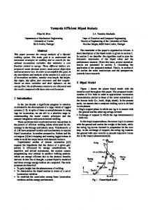
Figure 4.3: Reachable Space of ATRON Meta-Modules. Examples of the six types of meta-module are shown in (a)-(e). (e) Represents both meta-module type 5 and 6 since they have identical reachable-spaces. Small black spheres are vertices and lines are edges in the graph of the reachable-space. For simplicity in this illustration, only the position of one of the modules comprising the metamodule is used to visualize the states. For type 2 and 3 the top module is used and for type 5 and 6 the middle body module is used.
38
CHAPTER 4. CONTROL OF ATRON USING META-MODULES
Figure 4.4: A meta-module of type 6 must never emerge or stop if it does not have precisely this orientation.
so that a centre (body) module is connected to two modules (legs), one on each hemisphere, see figure 4.2(c). The meta-module is able to perform 8 different meta-actions. First, the meta-module connects to a neighbour module using a hemisphere on a leg-module not connected to the body-module. Second, all other neighbour modules are disconnected. Finally, the connected leg-module or the body-module performs a rotation either left or right. Such meta-actions allow the meta-module to move as a two legged walker on a flat surface of ATRON modules. Meta-module type 5 expands meta-module type 4 with 4 extra metaactions. For simplicity we will not explain the meta-action’s blueprint but only their effect. 2 meta-actions allow the meta-module to move one leg-module so that it connects to the other leg-module, which then becomes a new bodymodule. The last 2 meta-actions either rotate the meta-module 90 or -90 degrees, changing its orientation. The 4 extra meta-actions require the help of a neighbour module. This meta-module type is further explained in section 4.4.1, see also figure 4.5. Meta-module type 6 expands meta-module type 5 but not with extra meta-actions. Instead we put constraints on the emerging and stopping or1ientation of a meta-module. Meta-modules may only start or stop in precisely the orientation shown in figure 4.4. The motive is to help the emergence of flat structures of modules, on which it is particularly easy to move on for this meta-module type.
4.3.3
Characteristics of Meta-Module Types
Experimental Setup We measure the characteristics of the ATRON meta-modules in simulation as they perform a shape-changing task. The task is to shape-change one randomly generated structure of modules to another randomly generated goal structure.
4.3. SELECTING A META-MODULE TYPE
39
Meta-modules are centrally controlled and only one meta-module is moved at each time-step. In each time-step we calculate the reachable space of each of the possible meta-modules in the structure. From the reachable-spaces we find for each meta-module the state which will minimize the distance between the current and goal structure. The corresponding difference in distance we call a metamodule potential to decrease distance (PDD). Then the meta-module with the highest PDD is selected and it emerges, moves to and stops at the state which realizes its PDD (in a single time-step). Using this control strategy the distance between the starting structure and the goal structure will gradually decrease or stabilize, but it will never increase. Note that this control strategy is not how we intend to control the meta-modules. The purpose is only to have a common test scenario under which the different meta-module types may be evaluated. Characteristics of the different meta-module types are measured as the average of 10 different random shape-changing tasks. In each experiment a total of 90 modules are used in the initial and goal structure. Each experiment runs for 20 time-steps which in most cases is plenty for the result to stabilize. Structures of modules are randomly generated using the following algorithm: Starting with a single seed module, the algorithm repeatedly insert a module to the structure, at a randomly selected, unoccupied connector on a module, part of the structure. This algorithm produces initial and goal structures, which on average have an initial overlap of 45%. Distance between two structures (S1 and S2) is measured as the sum of distances between the modules in S1 to S2. The distance between a module and a structure is measured as the Euclidean distances from the module to the nearest module in the structure. Task Related Characteristics Task-related characteristics measure how well the meta-module performs the shape-changing task. We measure the efficiency as the effect achieved (decrease in distance between structures) compared to the number of rotations performed by modules during the task. Effectiveness is measured as the relative decrease in distance between the current and goal structure after 20 time-steps. Ef f iciency
=
Ef f ectiveness =
Dstart − Dend #Rotations Dstart − Dend Dstart
(4.1) (4.2)
Meta-Module Related Characteristics Meta-module related characteristics measure the individual and cooperative capabilities of meta-modules of a particular type. The system should contain a high proportion of moveable modules which can move as part of a meta-module, that is, modules which are not locked in place by constraints on their movement from their morphology and/or through blocking from other modules. We define
40
CHAPTER 4. CONTROL OF ATRON USING META-MODULES
this characteristic as system moveability. It is measured as the ratio between the number of moveable modules and modules in total in the structure. Similarly, a meta-module should be able to move freely on the surface of other modules. We measure meta-module moveability as the ratio between the number of connectable modules and the total number of modules in the structure. Connectable modules are the modules the meta-module, within its reachable space, is able to connect to. #M oveableM odules #M odules #ConnectableM odules M etaM oduleM oveability = #M odules SystemM oveability =
(4.3) (4.4)
When a meta-module moves, side effects may have a beneficial or undesired effect on the other meta-modules. We measure side effects in terms of change in the meta-modules’ potential to decrease distance (PDD). While performing a shape-change task side effects may occur at each time-step, from i to i + 1. In terms of distance, D, and PDD this can be expressed as difference equations: Di+1 mms X
P DDi+1
max = Di − P DDi→i+1 mms X max = (P DDi ) − P DDi→i+1
+SideEf f ectsi→i+1 In each time-step the meta-module with a maximum PDD (P DDmax ) moves to the corresponding state, this decreases the distance between the current and goal structure. However, as a side effect, the PDD of the other meta-modules (mms) in the system may also change. The sum of the side effects from timestep i = 0 to i = n may be calculated as: i=n X
SideEf f ectsi→i+1 = (D0 − Dn ) −
mms X
(P DD0 − P DDn )
i=0
In general, the starting distance may be much larger than the starting sum of PDD, which means that the side effects should be positive. For the shape-change to be completed at time-step i = n, the sum of side effects should be: i=n X
SideEf f ectsi→i+1 = D0 −
mms X
P DD0
i=0
From these considerations we define the side effect balance which is positive if the movement of meta-modules generates beneficial side effects: SideEf f ectBalancei = Pmms
D0 − Di −1 (P DD0 − P DDi )
(4.5)
4.3. SELECTING A META-MODULE TYPE
41
Table 4.2: Efficiency of meta-module types. Type of Meta-Module Type 1 Type 2 Type 3 Type 4 Type 5 Type 6
Mean Efficiency 0.89 1.31 1.18 0.29 0.34 0.36
95% Confidence Interval [0.76, 1.01] [1.17, 1.43] [1.06, 1.31] [0.26, 0.32] [0.28, 0.41] [0.28, 0.44]
Table 4.3: Effectiveness of meta-module types. Type of Meta-Module Type 1 Type 2 Type 3 Type 4 Type 5 Type 6
Mean Effectiveness 0.20 0.21 0.62 0.66 0.66 0.51
95% Confidence Interval [0.17, 0.24] [0.17, 0.24] [0.58, 0.66] [0.58, 0.73] [0.59, 0.72] [0.46, 0.56]
Table 4.4: System moveability of meta-module types. Type of Meta-Module Type 1 Type 2 Type 3 Type 4 Type 5 Type 6
Mean System Moveability 0.43 0.76 0.67 0.67 0.69 0.36
95% Confidence Interval [0.40, 0.45] [0.72, 0.79] [0.62, 0.71] [0.62, 0.72] [0.63, 0.74] [0.34, 0.39]
Table 4.5: Meta-module moveability of meta-module types. Type of Meta-Module Type 1 Type 2 Type 3 Type 4 Type 5 Type 6
Mean Meta-Module Moveability 0.096 0.088 0.21 0.23 0.28 0.79
95% Confidence Interval [0.09, 0.10] [0.087, 0.090] [0.19, 0.22] [0.21, 0.25] [0.27, 0.29] [0.76, 0.81]
Table 4.6: Side effect balance of meta-module types. Type of Meta-Module Type 1 Type 2 Type 3 Type 4 Type 5 Type 6
Mean Side Effect Balance -0.10 -0.28 -0.49 -0.66 -0.71 0.73
95% Confidence Interval [-0.24, 0.052] [-0.32, -0.23] [-0.55, -0.42] [-0.69, -0.63] [-0.74, -0.67] [ 0.33, 1.33]
42
4.3.4
CHAPTER 4. CONTROL OF ATRON USING META-MODULES
Results and Conclusion
The task-related characteristics of the different meta-module types are shown in table 4.2 and 4.3. In terms of efficiency the one- and two-module metamodule (type 1, 2 and 3) performs much better than the three module metamodules (type 4, 5 and 6). Meta-module type 3, 4 and 5 performs similar in terms of effectiveness (0.62, 0.66 and 0.66). Such effectiveness is acceptable in a range of applications which does not require shape-change into precisely specified structures. The meta-module related characteristics of the different meta-module types are shown in table 4.4, 4.5 and 4.6. Meta-module type 6 stands out since it is highly moveable and has a positive side effect balance; however, it is not high enough to also have a high effectiveness. Because of its extra meta-actions meta-module type 5 is slightly more moveable than type 4. Overall types 3 and 5 seem to be the best choices of types investigated. From the effectiveness we see that both have the ability to shape-change a structure of modules to an acceptable extent. Both are highly moveable and most of the modules in a system are able to move as part of a meta-module at any given time. One detail, however, differentiate the two meta-module types. Type 3 requires the help of neighbor modules to perform 28 out of 32 different meta-actions, while type 5 only requires help in 4 out of 12. This make type 3 less autonomous than type 5 and presumably also less robust. So in conclusion we select meta-module type 5 for further investigations.
4.4 4.4.1
Evolving Control for Meta-Module The Selected Meta-Module Type
In section 4.3 we investigated six different meta-module types and found that meta-module type 5, were the best type investigated. In this section we evolve an artificial neural network based controller to control this meta-module. First we will explain the meta-module type in somewhat greater detail. The meta-module type 5 is composed of three ATRON modules: one centre module (body) is connected to two other modules (legs), one on each hemisphere, see figure 4.5(a). To move meta-modules perform meta-actions, which consist of a sequence of connections, disconnections and ±90 degree rotations. The meta-module is able to perform twelve different meta-actions which fall into three different blueprints: Blueprint 1 (8 meta-actions): Meta-actions following this blueprint allow the meta-module to move as a two legged walker on a flat surface of modules. First, the meta-module connects to a structure-module using a hemisphere of a leg which is not connected to the body. Second, the meta-module is disconnected from all other modules. Third, either the connected leg-module or the bodymodule makes a ±90 degree rotation, as illustrated in figure 4.5(e) and 4.5(d). Blueprint 2 (2 meta-actions): The ∗-marked module in figure 4.5(b) is required to help the meta-module when performing this meta-action. The four modules perform a sequence of connections, disconnections and rotations, which
4.4. EVOLVING CONTROL FOR META-MODULE
(a) ATRON module.
Meta- (b) Meta-action: corners.
43
Turn around (c) Meta-action: Shifting orientation.
(d) Meta-action: Rotation of body-module.
(e) Meta-action: Rotation of leg-module.
Figure 4.5: Illustrations of the morphology of the ATRON meta-module type 5 and its meta-actions. The dark modules comprise the meta-module. The ∗marked modules in (b) and (c) are required to participate in the corresponding meta-actions.
makes it turn around a ”corner” as illustrated in figure 4.5(b). A different metaaction following the same blueprint allows it to turn around a corner in the opposite direction. Blueprint 3 (2 meta-actions): The ∗-marked module in figure 4.5(c) is required to rotate one leg-module towards the other leg-module, which then becomes the new body-module of the meta-module. Similarly a meta-action that rotates the other leg follows this blueprint. The effect of these meta-actions is to shift the orientation of the meta-module as illustrated in figure 4.5(c). The combination of morphology and meta-actions provides the meta-module with a high ability to move on the surface of other modules. Movement is achieved by performing a sequence of meta-actions.
4.4.2
Artificial Neural Network Controller
Modules make decisions concerning: 1. When the module should emerge as part of a meta-module? 2. Which meta-actions the meta-module should perform to move? 3. When the meta-module should stop? Decisions are made by three feedforward, 3-layer, sigmoid activation function, artificial neural networks (ANN), one for answering each of the questions. The controller calculates at runtime a number of inputs to the ANN’s. The inputs are calculated based on positions of attraction-points and the state of
44
CHAPTER 4. CONTROL OF ATRON USING META-MODULES
the local surrounding, such as positions and orientation of nearby modules and obstacles. In this subsection we first we explain how the meta-modules calculate a subset of their reachable-space from which the inputs to the ANN’s are calculated. Second we explain how the ANN’s are used to control the meta-modules. Meta-modules calculates a subset of their Reachable-Space Meta-modules calculate online a small subset of their reachable-space, to produce inputs for the ANN’s: 1) The meta-module builds a map of the local surroundings using neighbor to neighbor communication. The communication range is limited to six neighbors away. The map contain information about which positions, in the ATRON lattice, are known (by modules) to contain passive modules, modules part of a meta-module, obstacles and which positions are empty. 2) The reachable-space subset is calculated using the map in a breadthfirst manner. Initially the subset only contains one state - the actual state of the meta-module. Iteratively the reachable-space subset is expanded by repeatedly applying rules to the states in it. Rules correspond to meta-actions, so in total there are twelve rules one for each meta-action. A rule has a pre-condition which states which positions relative to the meta-module should be empty, which should contain passive modules and constraints on the orientation of the metamodule (for some meta-actions). A rule also has a post-condition which give the new state of the meta-module relative to the old one. To avoid computational explosion, states already seen are not recalculated and a fixed number (12) of iterations on the graph are done. This keeps the size of the graph down. Based on 5000 test samples there are on average 83 and a maximum of 687 vertices in the graph. The relative small size of the graph enables it to be calculated at runtime on the ATRON modules. Emergence of Meta-module With a low probability a passive module will attempt to emerge a meta-module. It randomly selects two passive neighbour modules, one on each hemisphere. It then calculates the reachable-space subset of that meta-module. From this it calculates the following inputs to an ANN which have 3 neurons in input-layer, 3 neurons in hidden-layer and 1 neuron in output-layer: • Distance to nearest attraction-point from current state of the meta-module. • Distance to nearest other meta-module from current state of the metamodule. • Biggest known possible reduction in the distance between the meta-module and its nearest attraction-point. The distance is calculated as the sum of the Euclidian distances for the three modules in the meta-module. If the output value of the ANN is greater than 0.5 the meta-module will emerge and the ANN’s for movement and stopping will control the meta-module.
4.4. EVOLVING CONTROL FOR META-MODULE
45
Movement of Meta-module When a meta-module has emerged it starts to move, by selecting one of the twelve meta-actions. The selected meta-action is then performed and the process is repeated. An ANN with 4 neurons in input-layer, 4 neurons in hidden-layer and 1 neuron in output-layer is used to select which meta-action to perform next. Each state in the reachable-space subset is evaluated separately. We make extensive use of the shortest path sequence of meta-actions (SPSM) that brings the meta-module from its current state to the state being evaluated. The following inputs are given to the ANN for each state: • Number of meta-actions in the SPSM. • Number of common meta-actions between the current SPSM and the previous SPSM. The previous SPSM is the latest sequence of meta-actions from which the meta-module performed the first meta-action. • Shortest distance to another meta-module, measured from a state along the SPSM. • Reduction in distance between the meta-module and its nearest attractionpoint, if it moves to the state being evaluated. The state, which is being evaluated, is assigned a fitness value from the output of the ANN. The state in the reachable-space subset which has the highest fitness value is selected. And the first meta-action in the corresponding SPSM is then performed by the meta-module. Since the structure of modules is dynamic and information in the map may be incomplete it happens that the performance of a meta-action fails. The meta-module then recovers as good as possible, e.g. if a rotation fails because of collision the rotation will be inverted and the meta-action cancelled and ignored until another meta-action succeeds. Stopping of Meta-module Each time the meta-module has performed a meta-action it decides if it is time to stop or perform another meta-action. An ANN with 5 neurons in input-layer, 3 neurons in hidden-layer and 1 neuron in output-layer makes this decision based on the following inputs: • Biggest known possible reduction in the distance between the meta-module and its nearest attraction-point. • Distance to nearest attraction-point from current state of the meta-module. • Number of possible connections between the meta-module and its passive neighbors modules. • Reduction in distance to nearest attraction-point over the last five metaactions.
46
CHAPTER 4. CONTROL OF ATRON USING META-MODULES • Number of cancelled meta-actions (e.g. because of collision) in the lifetime of the meta-module.
If the output of the ANN is greater than 0.5 the meta-module will stop moving and connect to all passive neighbor modules.
4.4.3
Evolution of Artificial Neural Network Controller
Evolution is chosen to optimize the value of the ANN’s weights, since there is no obvious way of training the network and since evolution may be good to exploit cooperation between meta-modules. The actions of one meta-module may affect other meta-modules in ways which are difficult to analyze and harder to exploit. Encoding of Artificial Neural Networks The topologies of the networks are fixed, only the weights are optimized by means of evolution. The genome of each individual is the 50 weights which are directly encoded as floating points values. Initially the weights have random values between -0.5 and 0.5. Genetic Algorithm A simple genetic algorithm is used. Each generation consist of 100 individuals. The individuals in each generation are evaluated and their fitness calculated. The 3 fittest individuals are used as elites and directly copied to the new generation. A child has two parents randomly selected from the group of the 25 fittest individuals. The child is produced by using a randomized 12-point crossover and a mutation rate of 5%. When mutating a gene it is with equal likelihood replaced with a new random value or a small random value added to or subtracted from the gene. Fitness Evaluation To evaluate the individuals they perform two tasks, which are randomly generated with the algorithm described in section . A task is to shape-change a structure of 50 modules into another random structure specified by 50 inhibiting attraction-points, placed within the ATRON lattice. The individuals in a generation are all evaluated on the same random tasks, but from generation to generation new random tasks are generated. A task is terminated if there within 300 time-steps (approximately 45 sec. on the physical modules) has been no decrease in Euclidian distance between the modules and the attraction-points. The fitness of an individual is calculated as the average fitness from each of the two tasks. The fitness from a task is simply the effectiveness, defined in equation 4.2, which is calculated as the relative change in distance between the structure of modules and the attraction-points: f itness = (Dstart − Dend )/Dstart . A number of evolutionary experiments were performed before reaching the details described above. The final controller, used for experiments in this work, was
4.5. EXPERIMENTS
47
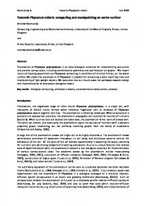
Figure 4.6: The graph show the average and highest fitness for each generation, when evolving the weights of the artificial neural network controller for the ATRON modules.
obtained from a evolutionary run for which the fitness graph is shown in figure 4.6. The noise in the fitness evaluation indicates that some tasks are harder to solve than other.
4.5
Experiments
In this section we first demonstrate how shape-change and self-repair behaviors may be achieved using attraction-points and the evolved artificial neural network controller. Second we present experiments to validate that the evolved controller is scalable and fault-tolerant. Third we present proof of concept experiments, with meta-modules, on the physical platform.
4.5.1
Shape-Change and Self-Repair
Experiment: Support Unstable Roof In earth quake or cave environments it might be desirable to have systems which can support an unstable roof. In this experiment a random structure of 500 modules initially lay on a floor. A roof is positioned at the height of 26 modules above the floor. The target functionality is the same as that of a pillar. To achieve this functionality 117 inhibiting attraction-points are placed in a column shape. As the robot change-shape upwards the attraction-points of lower positions will be inhibited by the modules at their positions. The result of this simulated roof supporting experiment is shown in figure 4.7.
48
CHAPTER 4. CONTROL OF ATRON USING META-MODULES
Figure 4.7: In order to support an unstable roof the structure of 500 ATRON modules shape-change, stretching upwards to achieve the functionality of a pillar. The process is guided by attractions-points which are shown as small spheres.
Experiment: Bridge Gap In a range of scenarios it may be useful to have a system which can build a bridge across a gap. In this experiment 1000 ATRON modules are initially placed in a random structure. A single non-inhibiting attraction-point is placed as shown in figure 4.8. The shape of the ATRON robot stretches towards the attractionpoint, effectively building a bridge across the gap. The ATRON simulator does not support physics. During this experiment long thin arms of ATRON modules are build, which most likely would break off in a real-world gravity environment. This problem could be reduced by adding more attraction-points to guide the shape-change. Experiment: Self-Repairing Bone A future miniaturization of modules would open up for new possible applications, e.g. smart material which could self-repair. This experiment demonstrates the use of miniature ATRON modules in a self-repair scenario. Initially, using a CAD model, 3426 ATRON modules are assembled in the form of a bone, see figure 4.9. A total of 1663 inhibiting attraction-points are placed at the same positions as ATRON modules which is connected to eight neighbours. This leaves the surface of the bone free of attraction-points. At timestep 20, 114 modules are removed which damage the strength of the bone. Since the removed modules no
4.5. EXPERIMENTS
49
Figure 4.8: A structure of 1000 ATRON modules build a bridge across a gap. A single non-inhibiting attraction-point is used to guide the modules shape-change.
longer inhibit the attraction-points this triggers the emergence of meta-modules. After 1000 timesteps (app. 150 sec.) the modules have rearranged themselves, the bone is self-repaired and its strength largely recovered.
4.5.2
Scalability and Failure Tolerance
Experiment: Scalability The ANN controller was evolved using tasks containing 50 modules. To investigate how the controller scaled to shape-changing structures of more modules we measured the controller’s performance as it performed a series of tasks. Tasks were of the same random type as used when evolving the controller, but the number of attraction-points and modules were varied from 50 to 1200 in steps of 50 modules. The stop criteria were no improvement in 300 time-steps. The graph in figure 4.10 indicate that the relative change in distance, when performing a task, does not decline as a function of the number of modules in the structure. Therefore the experiment indicates that the evolved controller scales up to at least 1200 modules. Further experiments with 1500, 2000 and 2500 modules indicate that the evolved control scales even to this number of modules. With 2500 modules the average (based on 10 exp.) decrease in distance is 0.345. For comparison the equivalent graph of an alternative controller is also shown in figure 4.10. This alternative controller is hand-coded based on its reachable-
50
CHAPTER 4. CONTROL OF ATRON USING META-MODULES
Figure 4.9: Self-repair of a bone build from 3426 ATRON modules: At timestep 0, there is no activity. At timestep 20, the bone breaks. At timestep 1000, modules have rearranged themselves to self-repair the bone.
4.5. EXPERIMENTS
51
Figure 4.10: The graphs show how the relative change in distance of an evolved and an alternative hand-coded controller scale from 50 to 1200 modules in the structure. Each point in the graphs is calculated as the average of 10 tasks. Calculated from the entire interval, the evolved controller has a 95% confidence interval for the mean of 0.325 to 0.345 and a standard deviation of 0.0787. The alternative controller has a 95% confidence interval for the mean of 0.237 to 0.260 and a standard deviation of 0.0875. The evolved controller performs significantly better than the alternative controller.
space subset and does not use ANN’s. The alternative controller: • Emerge, if it is able to reduce its distance to the nearest attraction-point. • Move, along the shortest path of meta-actions, towards the state that minimize its distance to an attraction-point. • Stop, if it no longer is able to reduce its distance to the nearest attractionpoint. The experiments indicate that the evolved controller performs significantly better than the alternative controller. Figure 4.11 shows how the time to self-reconfigure scales in relation to the number of modules in the structure. We can see that it in the interval from 700 to 2500 the time to self-reconfigure (without any decrease in effectiveness) is almost constant. This is somewhat counter-intuitive but may be a result of the high degree of modules able to move as a meta-module at any given time (system moveability) and the ability of evolution to exploit it. We can however not expect this time to be constant for much higher number of modules. Experiment: Module Failure Tolerate To investigate the evolved controller’s ability to tolerate catastrophic module failures, a series of experiments have been performed. The task is to support
52
CHAPTER 4. CONTROL OF ATRON USING META-MODULES
Figure 4.11: The graph shows an estimation of the time of self-reconfigure a given number of modules, from one random shape to another. The interval from 50 to 1200 is investigated in steps of 50 modules, from 1200 to 2500, experiments with 1500, 2000 and 2500 modules is performed. The grey area indicates standard deviation. Each point is the average of 10 trials.
Figure 4.12: The meta-module based control is fairly tolerant to module failures. The initial (random) configuration of 500 ATRON modules is shown on the left. The robot shape-change guided by attraction-points shown as small dots. On the right the result is shown for different amount of module failures. The failed modules are black and are failed from the start of the simulation.
4.5. EXPERIMENTS
53
Figure 4.13: The graph shows the performance of a 500 module robot as a function of module failures rate. The robot shape-change from an initial random configuration to support an insecure roof. Each point is the average of 10 experiments with varying starting configurations. Error-bars are 95% confidence intervals.
an insecure roof as the experiment described in section 4.5.1. The initial structure consists of 500 modules and 117 attraction points. If no module fails the robot will reach the roof and thereby support it. The experiment is rerun with failure rates of 5%, 10% and 15%. A failure rate of e.g. 10% means that initially and during the experiment 50 randomly selected modules out of the 500 ATRON modules are non-functional. This means that the modules are unable to communicate, rotate, connect or disconnect. The initial state of a connector is connected, so a failed module will generally lock other functional modules in place with its male connectors. The functional modules can not use the failed module to move on since they have no way of detecting it as a module, in fact it will be treated as an obstacle. As can be seen from figure 4.12 the robot is able to support the roof up to a failure rate of 10%, but the strength of the robot tends to become lower as the failure rate increase. Also the speed of changing shape declines when the failure rate increases. This tolerance to module failures emerge from the redundancy of modules and the used of distributed controlled meta-modules. In figure 4.13 we show how the performance of the robot decline when the module failure rate increase. We measure performance as effectiveness, see equation 4.2, although it is not a good performance measurement for this particular task, it is however a good general performance measurement for the ability to shape-change. We normalize the effectiveness of each task with respect the effectiveness on the same task in the case of 0% module failure rate.
54
CHAPTER 4. CONTROL OF ATRON USING META-MODULES
Figure 4.14: In this experiment a meta-module moves across a structure of modules following an off-line planned sequence of 15 meta-actions.
4.5.3
Physical Meta-Modules
This section present steps towards implementation of the meta-module concept on the physical ATRON modules. We present experiments with up to three meta-modules doing online planning moving on top of 24 passive modules. The scale and amount of experiments on the physical system is limited by one factor: The infra red communication between modules is quite unstable. We are currently working towards resolving this problem. Experiment: Basic Meta-Module Behavior Experiments have shown that the basic functionality of a meta-module is transferable to the physical modules. Figure 4.14 shows one example. It shows a meta-module of type 5 moving on a structure of modules. The fifteen metaactions performed by the meta-module largely cover the range of different metaactions types. The meta-module is controlled by the centre (body) module, which is programmed with a state machine type program for each of the different meta-action blueprints. The centre module sends commands (such as rotate and connect) to the two leg modules, that responds when they have finished their given command. The performed sequence of meta-actions is planned off-line. The theoretical maximum lifetime of the modules comprising a meta-module, is
4.5. EXPERIMENTS
55
Figure 4.15: In this experiment a meta-module dynamically calculates a shortest path of meta-actions to perform. The meta-module repeatedly moves shortest path from one randomly selected state in its reachable-space to another.
given by the battery lifetime which is above two hours. Experiment: Meta-Module Move on Surface (On-line planning) In these and the following experiments the meta-modules are doing on-line planning in their reachable space to find the sequence of meta-actions to perform. The meta-module uses an A* algorithm [43] to find shortest-paths of metaactions from its reachable-space (known at compile-time). In the experiment shown on figure 4.15 the meta-module selects a random state, moves (following shortest path) to that state, then selects a new random state and so forth. For each meta-action it performs it recalculates the shortest path, which allows it to adapt to possible changes in the environment or configuration of modules. The details of four experiments is shown in table 4.7. From this we can see that a meta-action on average takes 6.3 seconds to perform, inclusive the calculation of shortest path and the coordination between modules comprising the meta-module.
56
CHAPTER 4. CONTROL OF ATRON USING META-MODULES Exp.
#Meta-Actions
1 2 3 4 Total
8 48 38 93 187
Exp. Time (seconds) 52 330 228 570 1180
Second pr. Meta-Action 6.5 6.9 6.0 6.1 6.3
Table 4.7: This table shows the experimental result of four experiments with a single meta-module following online planned sequences of meta-actions. The number of meta-actions performed in the experiment, the duration of the experiment and average number of second pr. meta-action is shown. Exp.
#Collisions
1 2 3 Total
5 4 10 19
#Meta-Actions (performed) 32 24 38 94
#Meta-Actions (optimal) 20 17 20 57
Percent Longer Than Optimal 38% 29% 47% 39%
Table 4.8: This table shows the experimental detail of three different experiments, where a meta-module moves from a starting to a goal position around an obstacle. The number of cancelled meta-actions due to collision with the obstacle is shown. Also the number of meta-actions performed (including the cancelled) to moved to the goal state, along with the shortest path (without collision) is shown. The final column shows the ratio between the number of meta-actions performed and the shortest path.
Experiment: Meta-Module Move Around Unknown Obstacle In this experiment we demonstrate how a meta-module handles collisions with obstacles in its environment. By using its centre-encoder a meta-module detect an obstacle when it collides with it. When the meta-module is in the process of performing a meta-action and then detects a collision with an obstacle it performs a rollback rotation to the lattice-position it came from. The state in the meta-modules reachable-space is then assumed to be filled with an obstacle and is hereafter ignored when doing shortest-path search in the A* algorithm. The meta-module then finds an alternative shortest-path and follows that until it perhaps again collides with an obstacle. By repeating this pattern the metamodule is able to find its way around an unknown obstacles as demonstrated in figure 4.16. Table 4.8 summarize the results of three different experiments with unknown obstacles. We see that the path length found by the meta-modules, using this trial-and-error approach range from being 29% to 47% longer than what could optimally be achieved using global knowledge.
4.5. EXPERIMENTS
57
Figure 4.16: In this experiment the meta-module must move from one corner to the opposite corner. In its way there is an obstacle unknown to the metamodule. The meta-module detects the obstacle by collision and finds its way around it by trying alternative routes.
58
CHAPTER 4. CONTROL OF ATRON USING META-MODULES
Figure 4.17: In this experiment three meta-modules move on the same surface of modules. They do not communicate so they collide with one another, but the control system is able to tolerate this so that they can co-exist.
Experiment: Meta-Modules Co-Exist The main problem with having meta-modules co-exist is that they from time to time will collide with one another. The evolved controller does not have any explicit communication between meta-modules, and collisions do happen. To handle this we apply the same ”rollback” rotation strategy as for the unknown obstacles. In the experiment of figure 4.17 three independent meta-modules moves following shortest path of meta-actions from one randomly selected state to another. The meta-modules collide but the system handles this and the metamodules find their way around each other. Table 4.9 summarize two experiments with two and three meta-modules moving on a surface of 24 passive modules. During the experiment 12.5% and 19%, for two and three meta-modules respectively, of the performed meta-actions are cancelled due to collisions.
4.6. DISCUSSION
59
#Meta-Modules
#Meta-Actions
#Collisions
2 3
56 52
7 10
Collisions pr. Meta-Action 0.125 0.19
Table 4.9: This table shows the results of two experiments, with two and three meta-modules following online planned sequences of meta-actions. The number of cancelled meta-actions due to collision and the total number of meta-actions (including the cancelled) performed is shown, along with the ratio between them.
4.6
Discussion
The control strategy presented in this chapter has a number of important features: First of all it is shown to be able to handle the hard problem of controlling the ATRON system. Second it provides an easy approach to control large structures of modules through attraction points and has no requirements on the initial structure of modules. Also it is robust to module failures and transferable to the physical modules. Furthermore the control is distributed and every module runs an identical program which complies with the distributed and homogeneous nature of the hardware. Also the control is self-organizing and display emergent properties. It is highly parallel and scales to thousands of modules. However we can not expect this control strategy to scale to hundreds of thousands of modules or more. This is due to the very fact that the meta-module move on the surface of the structure and not through it. As more modules are added to the system, an increasing percentage of the modules will be trapped inside the structure. Another limitation with the method is that it does not produce very precise approximations of shapes, perhaps less than 50%. This is good enough in some applications but not in others. Finally it can not be claimed to be simple, but neither is the problem of shape-changing thousands of ATRON modules. There might very well be a solution, which is simple, minimal and better, but if so this has yet to be found.
4.7
Conclusion and Future Work
In this chapter we have explored the idea of shape change achieved using distributed controlled meta-modules. The meta-modules emerge from unstructured groups of modules moves from one place to another and then stop at a new position. We investigated six different combinations of meta-module morphology and meta-actions for the ATRON system. The morphology varied from 1 to 3 modules and the number of meta-actions from 4 to 32. Different characteristics of the meta-module types were measured as they performed the task of shape-changing a structure of ATRON modules. From these characteristics we selected a three-module meta-module type. On the basis of the meta-modules reachable-space graph we then evolved
60
CHAPTER 4. CONTROL OF ATRON USING META-MODULES
an artificial neural network controller for the selected meta-module type. The controller controls the emergence, movement and stopping of meta-modules composed of three ATRON modules. Tasks of the robot are specified using attraction-points which trigger meta-modules to emerge and move towards them. In simulation we then used the evolved controller on a number of different shape change examples containing thousands of ATRON modules. Also in simulation we verified that the control strategy scaled without decrease in performance from 50 to 2500 modules and used an almost constant time to selfreconfigure from 700 to 2500 modules. We also demonstrated that the evolved controller were tolerant to some degree of catastrophic module failures. On the physical modules we verified the basic functionality of a meta-module and performed a number of different experiments with meta-modules doing on-line planning to co-exist with other meta-modules and move around unknown obstacles in their environment. Further work includes a complete transference from simulation to the physical world of the results obtained with this meta-module based control of the ATRON system.
Chapter 5
Robot Building Blocks From Miniaturized ATRON Modules 5.1
Motivation
The current size (centimetre scale) of the ATRON modules limits the versatility of the ATRON robot. There are approximately 800 ATRON modules in a one cubic meter robot. So robots consisting of tens of thousands of modules would be very large and heavy. If however the modules were miniaturized to the scale of micro-meters it would open up new possibilities. Then robots could be assembled from millions, billions or trillions of modules. We would like such robots to take on the form and functionality of biological organisms, for example a cat! A cat is a complex organism consisting of perhaps a trillion cells. The cells are differentiated to undertake different functionalities needed in the animal body. At a higher level of abstraction the cells form different tissue types and from this we get our metaphorical inspiration. The idea is to assemble configurations of modules that roughly exhibit the functionality of different tissue types. Bones, muscles and neurons are examples of this, and may be important building blocks when assembling complex functionality robots, such as artificial cats, from miniaturized ATRON modules.
5.2
Why Size Matters!
In this section we will briefly consider what would happen to the properties of the ATRON modules if they were scaled down in size. For this purpose we use a simple spherical geometrical model of the ATRON module as sphere, see figure 61
62 CHAPTER 5. BUILDING BLOCKS FROM MICRO ATRON MODULES
(a)
(b)
(c)
Figure 5.1: (a) The model of a ATRON module is a sphere, with radius r. (b) The connector system is assumed to be parallel plate capacitors. (c) We measure the maximum possible length of a ATRON chain, which can carry its own weight (in gravity) without breaking apart.
5.1(a). A sphere has a surface area, S, and a volume, V, as follows: S
=
V
=
4πr2 4 3 πr 3
(5.1) (5.2)
Notice that the volume is dependent on the cube of the ATRON radius, r, while the surface area is dependent on the square of radius. This means that as things get smaller their surface area increase compared to the volume. And since the mass is dependent on the volume, an ATRON module will become lighter compared to its surface area when it decreases in size. This works to our advantage when scaling down the module size. In the following paragraphs we will consider the scaling effects on connector strength and self-reconfiguration speed. We will see that we can expect both connector strength and the speed of self-reconfiguration to increase relative to size. A more thoughtful review on scaling laws can be found in [119].
5.2.1
Connector Strength
Strength of connection decides the strength of the ATRON material. So let us consider a simple scalable connector system, which could be used to connect two ATRON modules. A metallic plate is mounted on the surface of each module, see figure 5.1(a) and 5.1(b). The metal plates will attract each other when they are charged with a charge, Q, of opposite signs. Assuming the metal plates to be parallel, we can model it as a parallel plate capacitor which means that the force attracting one plate towards the other is:
5.2. WHY SIZE MATTERS!
63
Figure 5.2: The graph shows the maximum length of a chain of ATRON modules witch can carry its own weight in gravity without breaking apart. Left axis in terms of number of modules and right axis in terms of absolute length in meters.
F =
κe �0 V 2 A 1 QE = 2 2d2
(5.3)
We then assume the plate area, A, to be 1/20 of the total surface area, the voltage drop, V, to be 100V and the distance, d, between the plates to be 1/100 of the sphere radius. The insulation material between the plates, could be muscovite mica whit a dielectric constant, κe = 5.4, and dielectric strength of 160 M V /m. One way to get a feel for the strength of the connectors are by calculating how long a chain of ATRON modules can be build without it breaking apart due to its own weight, see figure 5.1(c). We set the density of a single module to 1200 kg/m3 , which is the approximate value in the current macro-size implementation. Figure 5.2 shows the maximum chain length both in terms of number of modules and in absolute length. If a module had a radius of 1.0mm it would be able to carry a chain of 30 modules, if it were 0.1mm it could carry 30 thousand modules (that is 6 meters). Note that there would be a voltage breakdown of the insulation between the capacitor plates at module radius of 0.0625mm. Also note that if d was not dependent on r, but instead constant, the absolute length of the chain would be independent on the scale of the modules. In conclusion we can expect the interconnections of ATRON modules to become stronger relative to the module mass, when they decrease in scale. This will in turn make the robots assembled from ATRON modules stronger.
5.2.2
Speed of Self-Reconfiguration
The speed of self-reconfiguration is both dependent on the connecting and rotational speed, in the current implementation it takes about 6 sec. for an ATRON
64 CHAPTER 5. BUILDING BLOCKS FROM MICRO ATRON MODULES module to rotate 360 degrees and 2.5 sec to (dis)connect. The mass of a module is the important limiting factor in rotation, but this scales as the cube of the module radius. An important limiting factor of actuation strength is cooling, but cooling is dependent on the surface area which is proportional to the square of the radius. So the actuation strength compared to the module mass can be expected to increase (proportional to the radius) as modules scales down in size. A more thoughtful analysis done by Peris et al. [87] verifies this. This means that if a module scales by a factor of 10, say, from 1mm to 0.1mm the absolute speed of the module can also be expected to increase also by a factor of 10. On an absolute scale this means that if we can develop algorithms for self-reconfiguration that scales linearly with respect to the number of modules. The time to self-reconfigure a robot of a given size, say 1m3 , will be constant, independent on the size of the modules. Note that we here assume that the modules environment is able to absorb the thermal energy. If the modules were space-filling, which the ATRON modules are not, this might be problematic. Another uncertainty is the effect of friction, which increase drastically as things get smaller. This might be especially hard to avoid for a miniaturized ATRON module since its two rotational hemispheres are in contact. However, in conclusion, we can still expect the speed of the modules to increase as the scale of the modules decrease.
5.3
Biological Inspired Building Blocks
In this section we present different biological inspired building blocks assembled from ATRON modules. The building blocks may be used to assemble robots with complex functionality from millions of miniaturized modules.
5.3.1
Bone
Organisms use bones to support the weight of their body. Some of the most important properties of bones are therefore their high strength and light weight. The current implementation of the ATRON modules is well suited for such strength related functionality. A structure of modules connected in the lattice is much like the atoms in a crystal. Each module is interconnected with up to eight other modules through strong aluminium connector hooks. Two modules can not be ripped apart without breaking metal. This gives a structure of modules a relatively high strength. The mass density of an ATRON material is approximately 720kg/m3 , for bone the mass density is about 1900kg/m3 . So the ATRON material is lighter than bone. It is however also much weaker than bone: yield stress for the ATRON material is 0.067M P a [81] and more than 50M P a for human femoral bone [36]. Off-course such properties will change, when the modules decrease in size due to necessary changes in the mechanical design and the way the laws of physics scale. Both biological and ATRON bones are able to self-repair. In [21] a bone assembled from ATRON modules was first partly broken, compromising the strength of the bone. Then an emergent control
5.3. BIOLOGICAL INSPIRED BUILDING BLOCKS
(a)
65
(b)
Figure 5.3: (a) A structure of ATRON modules connected in the surface centered cubic lattice structure have high structural strength. (b) Part of an ATRONbone assembled from 3426 ATRON modules using a CAD-model of the bone, the CAD model is shown as a wire-frame. strategy (relying on meta-modules) self-repaired the bone, largely recovering its strength. Figure 5.3 illustrates the idea of assembling strong bone-like building blocks from ATRON modules.
5.3.2
Neuron
To coordinate the trillions of cells in the biological body, some sort of computation and communication must take place between the cells. Certain forms of coordination are slow such as chemical hormones through the bloodstream. Others are faster, such as electrical synapses between neurons. Coordination between ATRON modules is in most of our previous work distributed between the modules, much like the emergent coordination between cells. Communication in its current implementation is direct infra-red communication between neighbor modules. Furthermore each module is able to do a considerable amount of computation using their on- board microprocessors. In biological organisms, sensory neurons are used to sense the environment. Similar the ATRON modules is already equipped with different types of sensors such as acceleration, orientation and for sensing of internal states. This collection of sensors could be further extended e.g. to include the sensing of light, heat, touch, sound and chemicals.
5.3.3
Muscle
Muscles are able to contract and as a result produce a force. This force is for example used to move bones relative to other bones and as a result produce
66 CHAPTER 5. BUILDING BLOCKS FROM MICRO ATRON MODULES
(a)
(b)
Figure 5.4: ATRON-muscle made from 8 ATRON modules. The structure contracts by forming a compact helix shape. Such ATRON-muscles could be used as building blocks in complex functionality robots assembled from miniaturized ATRON modules.
Figure 5.5: Experimentally found contraction strength as a function of contraction length for a 6 module ATRON-muscle. Notice that the strength is highest when the ATRON-muscle is fully extended.
5.3. BIOLOGICAL INSPIRED BUILDING BLOCKS
(a)
(b)
67
(c)
Figure 5.6: Different joint types, that can be assembled using ATRON modules. (a) Hinge joint. (b) Hinge Joint assembled from ATRON modules. This joint type has a single degree of freedom and scales along the rotational axes. (c) A socket-ball joint assembled from ATRON modules. This joint type has three degrees of freedom and scales in three dimensions. It is crucial to minimize the friction between socket and ball for the joint to be efficient. The lattice can be realigned using ATRON-muscles as anchors. locomotion and/or manipulation. The ATRON modules are not designed with muscles in mind. It is, however, possible to assemble structures of ATRON modules that exhibit the contractive functionality of biological muscles. Long chain like structures where each module (except the end modules) are connected to two other modules, one on each hemisphere can contract by forming a compact helix shape, see figure 5.4. This is done only by actuation of the modules no self-reconfiguration is involved. Experiments have shown that this type of ATRON-muscle is able to contract by a factor of 4.2 or 76%. In its extended form the cross-sectional area is 11x11cm, in the contracted form it is 21x21cm. The contraction force is strongest when its fully extended and decrease rapidly as the ATRON-muscle shortens, see figure 5.5. In the fully extended form the contractive strength is about 120N and 165N for ATRON-muscles with length of respectively 4 and 6 modules. The maximum force delivered by the muscle increases with the number of modules, to a fixed level. This force level is higher than the force a single module can exert, because the angle between the modules and the direction of contractive force works as a gearing. The main disadvantage of the ATRON muscle is that it exerts a poor force/weight ratio. An ATRON-muscle of length 8 as in figure 5.4 is just barely able to lift its own weight, but as discussed in section 5.2 a miniaturization of the ATRON system can be expected to would improve the force/weight ratio. The strength of an ATRON-muscle could be scaled up by having a number of muscles in parallel just as muscle fibers in biological muscles.
5.3.4
Joint
Joints are needed to allow one ATRON-bone to be rotated relative to another ATRON-bone using the contractive force of ATRON-muscles. A single ATRON
68 CHAPTER 5. BUILDING BLOCKS FROM MICRO ATRON MODULES module may be considered a rotational joint, but this does not scale well, since this single module should be able to withstand the weight of the bones and the forces generated by the muscles. Using ATRON modules we can assemble a hinge joint, see figure 5.6(a) and 5.6(b) , that has improved strength compared to the single module joint since it distributes the forces on a larger number of modules. This hinge joint has the feature that the modules on both sides of the joint always can return to the same global lattice. This is important in order to have complete reversibility when changing from one shape to another. Ballsocket type joints, see figure 5.6(c), can not be assembled from ATRON modules without separating the lattice of the ball from the lattice of the socket. The solution to maintain reversibility is to use ATRON-muscles as anchors between the two lattices. The idea is that the ATRON-muscles can function as bridges for transporting modules and communication from one lattice to the other. And that they can realign the lattices by contraction. Friction between the ATRON ball and socket should be minimized by careful design of the outer shape of the modules. This anchoring technique could equally allow the construction of other types of joints, e.g. saddle joints.
5.3.5
Other considerations
Biological organisms use the bloodline to transport energy to the individual cells. Similarly on the ATRON system power is shared amongst the modules through the connectors-hooks. This feature has, however, been removed due to technical difficulties in the current version of the electronics. In a miniaturized version of the modules, power-sharing would be necessary. Biological organisms use skin as a shield from the environment. Similarly protection from the environment for a large cluster of ATRON modules could be achieved using sheets of ATRON modules. Such a sheet, much like the one in figure 5.6(b), can bent if certain of the inter-module connections are disconnected. A sheet made from a grid of ATRON-muscles can both bend and also stretch.
5.4
Discussion, Summary and Future Work
In this chapter we first discussed how a miniaturization of the ATRON modules would affects their properties. We saw that we can expect to have stronger and faster modules compared to their weight, when they scale down. Then we discussed how to use ATRON modules for construction of biological inspired building blocks. Properties of structures resembling bone, joints and muscles, were investigated using the current macro-size modules. The long-term goal of this research is to reproduce the entire workings of biological organisms only using massive numbers of miniaturized robotic modules. This goal may very well be unreachable using only ATRON modules. However, the example of biological organisms proves the principle that complex beings can be constructed using many, relatively simple, buildings blocks. And we believe that using metaphori-
5.4. DISCUSSION, SUMMARY AND FUTURE WORK
69
cal inspiration from biology may help us achieve this goal. Future work towards this includes: identifying more necessary building blocks and their properties, simulate building blocks to explore their use in massive-module robots and finally miniaturize the robot modules to do it for real.
70 CHAPTER 5. BUILDING BLOCKS FROM MICRO ATRON MODULES
Chapter 6
Discussion and Future work 6.1
Future Challenges of Shape-Changing Robots
The goal of our research is to build robots that are versatile, robust and adaptive. Our approach to achieve this is by building shape-changing, self-repairing, selfassembling robots. Lattice-based modular robots appear to be a good way to go about this problem. As the ATRON example shows the modules can be constructed using relatively traditional mechanics. The robots assembled from such modules may be structural strong and able to achieve any desired shape. Also the control of the individual modules in a lattice-based self-reconfigurable robot also seems to be manageable. The lattice defines a simple mapping between the desired shape of a robot and the positions of its modules. The abilities of the modules are well defined as they move from one lattice-position to another. Also some level of tolerance to module failures and adaptation to the environment can be obtained through the proper use of redundancy and distributed control. However, the lattice-based design of systems, such as the ATRON, also poses a number of challenges: Module Failures The dependency between modules is quite high: A failure of one module will tend to escalate, which complicates the control problem and reduce the robustness. Interaction with Environment The lattice complicates interaction with the environment: The robot can adapt its morphology but only to the extent defined by the lattice. It is possible to build something rigid, but not something soft. Since the world does not fit within a lattice, interaction with the environment is problematic. Versatility The robots have limited versatility: It is not obvious how to assemble robots with complex functionality from many modules. Either the robot contains few modules or the functionality originates from shapechanging into structural strong structures. 71
72
CHAPTER 6. DISCUSSION AND FUTURE WORK
Self-Assembly Self-assembly becomes highly complex: The desirable scenario of having a robot self-assemble from modules lying unstructured in an environment is difficult, since the assembled structure of modules must fulfil the lattice invariant. Self-repair Self-repair as well is problematic: To remove a defect module from the centre of a large structure of modules, the defect module must be transported to the surface, which as well is a complex task. Shape-change Shape-change is slow: To change from one shape to another a high number of modules must move from one position to another. It is not always the case that a large portion of modules can be moved in parallel. For example with the ATRON meta-module based control only the modules on the surface move. The lattice-based self-reconfigurable approach to versatile, robust and adaptive shape-changing robots has quite a number of challenges. Some issues have already been addressed in this thesis, the meta-module based control strategy, from chapter 4, was shown to be robust to some degree of module failures. And real-world meta-modules were shown to be able to interact with obstacles in its environment. In simulation the meta-module based approach was shown to be able to shape-change and self-repair. Similarly the miniaturized building blocks from chapter 5 address the problem of robots as versatile as biological organism. However the proposed solutions resolve none of the challenges completely. We are still a long way from robots which are truly versatile, robust and adaptive. So where should we go from here? - The following three sections suggest three different answers. First, in section 6.2, we consider how the ATRON system could be improved, by redesigning the mechanics and electronics. Second, in section 6.3, we propose a new self-reconfigurable robotic system which is very much based on the ATRON system but has improved motion capabilities. Finally, in section 6.4, the concept of ”robotic deformable sheets” is introduced and advantages and disadvantages compared to self-reconfigurable robots are explained. As it turns out these three directions, combined with the miniaturized ATRON building blocks, are also the directions of my future thesis work.
6.2
Redesigning the ATRON Hardware
Putting aside a few bugs, the current hardware implementation of ATRON is in general in a fine condition. However a number of issues have been identified which should be considered if the modules ever should be redesigned from scratch: Unisex connector It is a general problem with male-female connector systems that it complicates the control problem, since it become important how the male-female connectors are positioned. This is a trade-off with the presumably more complicated design of a unisex connector.
6.3. THREE DEGREE OF FREEDOM ATRON MODULES
73
Double Sided Disconnect A failed (dead) module may lock up to four other modules in place through its male-connectors, having a grave effect on the shape-changing ability of the robot. The best solution is to use a unisex connector where each connector is able to disconnect independent from the other connector. Connected Sensor Sensors should be added to allow a module to sense whether or not an attempted connection did succeed. In the current implementation connection is done open-loop. Connectivity Sensor When a disconnection is made there is the chance that it will break the connectivity of the structure of modules (a group of modules will fall off). A sensor for detecting this would simplify the control complexity. The best known solution for preventing the connectivity to break relies heavy on the use of communication, which then slows down self-reconfiguration. Manual Assembly Mechanical connectors make the manual assembly of robots tedious. To increase the usability of the system this issue should be considered. Power-Sharing In an earlier version of the electronics the modules were able to share power through the connectors. In the current version of the electronics this feature has been removed since there was a risk of shortcircuiting the modules. This means that each module must be charged separately which complicates the use of the modules. To have truly robust robotic systems, autonomy in relation to power would be necessary and power-sharing could be a step towards this. Smaller and Stronger The size and strength of the modules limits the usability of the modules. Stronger modules compared to their weight would make the system more fit for locomotion and manipulation tasks. Robustness In order to bring the ATRON system closer to applications, robustness in relation to the environment must be considered. Making the ATRON modules resistant to water, shock and dust would allow experiments in real world scenarios (e.g. earth quake). Not everything can be fixed with an optimization of the ATRON hardware design. Especially the motion capabilities (in relation to self-reconfiguration) does not improve, which is one of the major limitations with the current ATRON design.
6.3
Three degree of freedom ATRON modules
One of the main limitations with the design of the ATRON modules is its motion capabilities. The strict motion constraints increase the control complexity and decrease the ability to self-reconfigure. The known best method for
74
CHAPTER 6. DISCUSSION AND FUTURE WORK
(a)
(b)
Figure 6.1: (a) The current implementation of the ATRON system has a single rotational degree of freedom. (b) A possible future module design that generalizes the ATRON system, could have three rotational degree of freedom.
self-reconfiguring large structures of ATRON modules, the meta-module based approach, is unable to self-reconfigure groups of ATRON modules into precise approximations of shapes. However, there exists an obvious generalization of the ATRON design, which seriously decreases the motion constraints. This system, BTRON for now, increase the rotational degrees of freedom from one to three degrees. This module is able to rotate around three perpendicular axes instead of the one rotational axes of ATRON, see figure 6.1. The modules are still positioned in a surface centred lattice structure however, in contrast to ATRON, they will all have the same orientation. With the extra degrees of freedom, the system only gains functionality, since anything possible with the ATRON system is also possible with the BTRON system. I relation to motion capabilities the system represents a serious improvement. The modules might self-reconfigure so easily that the work on abstract types of omnipotent modules can be applied to the system. Future work includes a more thoughtful investigation of this.
However, the mechanical design will be more complicated. For the three degree of freedom rotational axes one might taking inspiration from the mechanics of a Rubic’s Cube. Concerning the connectors, they must also be redesigned to be symmetrical around the connection-axes. The main question therefore remains - can we construct such a system?
6.4. ROBOTIC DEFORMABLE SHEETS
(a)
75
(b)
(c)
Figure 6.2: The concept of robotic deformable sheets. A 2D sheet able to bend and fold itself into 3D shapes.
6.4 6.4.1
Robotic Deformable Sheets The concept
This section present a novel concept, which we1 name ”Robotic Deformable Sheets”. The concept is inspired by the concept of self-reconfigurable robots, and the goal is quite similar: to have robots that dynamically and autonomously can change their shape appearance. The idea is to have 2D sheets of robotic material that can deform, by folding, extending and contracting, into approximation of 3D shapes. The material is build up by active elements that sit in a permanent grid. Each element is controlled in parallel and can by actuation, affect the global shape of the sheet. The concept of robotic deformable sheets is demonstrated in figure 6.2 where a 2D sheet bend and fold itself into a hollow 3D shape. Figure 6.3 shows the related PinArt toy. Its arrangement of pins allows it to be manipulated to take on a large range of different shapes. It is possible to actuate the individual pins of such a toy, however, there are also strict limitations on the types of shapes the surface can achieve using this kind of mechanism. In contrast to self-reconfigurable robots there are no modules that self1 The
concept is developed in cooperation with Kasper Støy
76
CHAPTER 6. DISCUSSION AND FUTURE WORK
Figure 6.3: Pin-art is an example of a 2D surface that can form 3D shapes. Pin-arts can be actuated, for example using pneumatic or SMA, however their are limitations on the types of shapes that can be achieved. reconfigures by moving on and (dis)connecting from other modules. This simplifies both the problems of hardware and control: Elements are mechanically simpler since they are interconnected in a permanent grid and only need to be able to perform simple actuation tasks. Elements should be unable to do any ”illegal” actions, since such illegal action e.g. disconnections that breaks connectivity, is complicating the control of self-reconfigurable robots. Shape shifting is produced entirely by local actuation and given by the state of the individual elements. Therefore we expect the shifting into a given 3D shape to be nearly trivial. Also shape-shifting is fast, only taking the time for a single element to reach its final state. This means that shape-shifting can be done in constant time, independent on the scale and number of elements comprising the system. Surely the application range of robotic deformable sheets is more limited than self-reconfigurable robots. The sheets can reach a large class of 3D shapes but not any shape is reachable, e.g. shapes with holes in them. Possible applications mainly take advantage of the shape shifting ability such as 3D physical screens, which amongst other things could be used for remote presence. But also manipulation application which requiring limited force, such as distributed manipulation on a surface. Other applications such as robot arms and locomotion are more infeasible, since they require higher strength than it is feasible to achieve with robotic deformable sheets.
6.4.2
Design Considerations
In order to implement a successful robotic deformable sheet, the following issues have to be taken into account: • What are the basic requirements of the elements?
6.4. ROBOTIC DEFORMABLE SHEETS
(a)
(b)
77
(c)
Figure 6.4: Three possible designs of the basic robotic element in the deformable sheets: (a) Element that can contract/extend such as a linear actuator. (b) Element that can control the angle to neighbor elements. (c) Element that can control how they bend. • How can the complexity of the elements be limited? • How can the elements be constructed to facilitate mass production and scalability? • How can a sheet maintain one given shape without constant use of energy? • How should the elements be put together? -in a grid? -and what grid? • How can the control of the individual elements produce the desired global behavior? Figure 6.4 shows three possible designs of some simple active elements for robotic deformable sheets. Common for the different designs are that they are shaped like beams and are permanently connected to other elements in each end. Such elements could either be able to contract/extend, control the angle to neighbor elements or bend. The pros and cons of the different element designs are still under investigation. However it is not obvious how to produce 3D shape from 2D sheets using the contraction/extension type element alone. For this the rotation and bending seems more appropriate. The problem with these is rigid constraints between the elements, which do not allow the surface area to change. One possible solution is to relax the rigid constraints by connecting the elements with a stretchable material. Another solution, is to have bistable element which never change the distance between elements, but jump between stable states to change the local curvature. This also solves the problem with constant energy consumption, since a sheet in a given structure would maintain its shape without any use of energy.
78
CHAPTER 6. DISCUSSION AND FUTURE WORK
(a)
(b)
Figure 6.5: (a) SMA-actuated element. A realistic deflection of such an element, if outer coating were applied, is indicated on the figure. (b) Bistable triangular grid of unactuated elements. Possible grid layout includes triangular, square and hexagonal grid. On top of the grid a flexible material, such as stretchable cloth or a flexible screen cold be placed. The latter could then show images that matched the shape of the sheet - this would be an implementation of a 3D physical screen.
6.4.3
Towards implementation
We have developed some early simple prototypes of the active element for deformable surfaces. The basis for the elements is bendable plastic material shape as a beam. Shape memory alloy (SMA) wires are used for actuation. SMA wire is able to contract by approximately 5% when heated and will return to its original length when cooled down. By stretching a SMA wire between the two ends on each side of the plastic beam, a bendable element can be build, see figure 6.5(a). The deflection of the element can be improved by adding a outer plastic layer to hold the SMA near to the beam [131]. This makes it possible to achieve relatively large bending motions from the relatively little motion of the SMA. A number of bistable, but unactuated, elements in a triangular grid can be see figure 6.5(b).
6.4.4
Summary and Future work
In this section we have presented the concept of ”Robotic Deformable Sheets”(RDS). We compared it to self-reconfigurable robots and concluded that using RDS we can, at the expense of versatility, achieve faster global shape shifting using simpler hardware and control. We discussed possible designs of the active elements, and presented a simple prototype of a bending element. Future work includes simulation of large-scale systems to explore the design requirements of the active elements. As well as a small scale ”proof of concept” physical imple-
6.4. ROBOTIC DEFORMABLE SHEETS
79
mentation of an active deformable sheet. Note that the concept of RDS and self-reconfigurable robots are by no means incompatible. Actually the Catoms, see section 2.1, modules might turn out to be a suitable basis element for RDS. A 2D grid of Catom modules assembled in the right configuration might be able to fold into 3D structures without any Catoms actually has to move - all Catom would have the same neighbors before and after self-reconfiguration. Such an approach would get the best from both the concept of self-reconfigurable robot and robotic deformable sheets: shape-shifting would be in constant time and the systems would be able to self-repair and self-assemble.
80
CHAPTER 6. DISCUSSION AND FUTURE WORK
Chapter 7
Conclusion This status report has presented some work toward realizing shape-changing robots. An important platform for shape-changing robots is self-reconfigurable robots. Self-reconfigurable robots can change shape by changing the interconnection of modules, by having modules connect/disconnect and move by actuation. A control strategy for controlling the shape of the ATRON self-reconfigurable robot was developed. The control stately is distributed and based on metamodules which emerge, move and stop. This is a novel approach. From simulated experiments the control stately was concluded to be suitable for many applications, scalable in the range of thousands of modules and failure tolerant to some extend. Experiments on the physical platform showed that the concept were indeed transferable to the real modules. A step towards functional shape-changing robots was taken by exploring the novel concept of biologically inspired building blocks assembled from selfreconfigurable modules. We showed that different types of building blocks, such as bone, neurons, muscle and joints could be realized using ATRON modules. This approach assumes that the modules at some point will be miniaturized. In this context we saw that we can expect the modules to become stronger and faster as they decrease in size. Finally a novel shape-changing robot concept was presented. ”Robotic Deformable Sheets” hold the potential to achieve faster shape-change using much simpler hardware and control than self-reconfigurable robots. We presented some initial design ideas and simple prototypes of the active elements comprising the sheets.
81
82
CHAPTER 7. CONCLUSION
Bibliography [1] F. H. Bennett and E. G. Rieffel. Design of decentralized controllers for selfreconfigurable modular robots using genetic programming. In Proceedings, Second NASA/DoD Workshop on Evolvable Hardware, 2000. [2] F. H. Bennett III, B. Dolin, and E. G. Rieffel. Programmable smart membranes: Using genetic programming to evolve scalable distributed controllers for a novel self-reconfigurable modular robotic application. In Proceedings of Genetic Programming (EuroGP’2001), pages 234–245, Lake Como, Italy, 18-20 April 2001. [3] H. Bojinov, A. Casal, and T. Hogg. Emergent structures in modular selfreconfigurable robots. In Proceedings, IEEE Int. Conf. on Robotics & Automation (ICRA), pages 1734–1741, 2000. [4] H. Bojinov, A. Casal, and T. Hogg. Multiagent control of selfreconfigurable robots. In Fourth International Conference on MultiAgent Systems (ICMAS), pages 143–150, Boston, Massachusetts, USA, July 2000. [5] D. Brandt. Comparison of a* and rrt-connect motion planning techniques for self-reconfiguration planning. In IEEE/RSJ International Conference on Intelligent Robots and Systems(IROS) (submitted), 2006. [6] D. Brandt, D. J. Christensen, and H. H. Lund. Versatility of applications for the atron self-reconfigurable robot. Robotics and Autonomous Systems Journal (draft), 2006. [7] D. Brandt and E. H. Østergaard. Behaviour subdivision and generalization of rules in rule based control of the atron self-reconfigurable robot. In Proceeding of International Symposium on Robotics and Automation (ISRA), pages 67–74. Secretaria de Educaci´on P´ ublica, 2004. [8] Z. Butler, K. Kotay, . Rus, and K. Tomita. Generic decentralized control for a class of self-reconfigurable robots. In Proceedings of IEEE International Conference on Robotics and Automation (ICRA), 2002. [9] Z. Butler, K. Kotay, D. Rus, and K. Tomita. Cellular automata for decentralized control of self-reconfigurable robots. In Proceedings, IEEE 83
84
BIBLIOGRAPHY Int. Conf. on Robotics and Automation (ICRA’01), workshop on Modular Self-Reconfigurable Robots, Seoul, Korea, 2001.
[10] Z. Butler, S. Murata, and D. Rus. Distributed replication algorithms for self-reconfiguring modular robots. In Proceedings, Distributed Autonomous Robotic Systems 5 (DARS’02), pages 37–48, Fukuoka, Japan, 2002. [11] Z. Butler and D. Rus. Distributed locomotion algorithms for selfreconfigurable robots operating on rough terrain. In Proceedings of IEEE International Symposium on Computational Intelligence in Robotics and Automation (CIRA’03), pages 880–885, 2003. [12] Z. J. Butler and D. Rus. Distributed planning and control for modular robots with unit-compressible modules. I. J. Robotic Res., 22(9):699–716, 2003. [13] J. Campbell, P. Pillai, and S. Goldstein. The robot is the tether: Active, adaptive power routing for modular robots with unary inter-robot connectors. In IEEE/RSJ International Conference on Intelligent Robots and Systems (IROS), Edmonton, Alberta Canada, August 2005. [14] A. Casal and M. Yim. Self-reconfiguration planning for a class of modular robots. Proceedings of SPIE, Sensor Fusion and Decentralized Control in Robotic Systems II, vol. 3839, pages 246–255, 1999. [15] A. Castano, R. Chokkalingam, and P. Will. Autonomous and self-sufficient conro modules for reconfigurable robots. In Proceedings, 5th Int. Symposium on Distributed Autonomous Robotic Systems (DARS’00), pages 155–164, Knoxville, Texas, USA, 2000. [16] A. Castano, W.-M. Shen, and Peter Will. Conro: Towards deployable robots with inter-robot metamorphic capabilities. Autonomous Robots, 8(3):309–324, June 2000. [17] A. Castano and P. Will. Mechanical design of a module for autonomous reconfigurable robots. In Proceedings, IEEE/RSJ Int. Conf. on Intelligent Robots and Systems (IROS’00), pages 2203–2209, Nov 2000. [18] A. Castano and P. Will. Representing and discovering the configuration of conro robots. In Proceedings, Int. Conf. on Robotics & Automation, Seoul, Korea, 2001. [19] G. Chirikjian. Kinematics of a metamorphic robotic system. In Proc. of IEEE Intl. Conf. on Robotics and Automation, pages 449–455, 1994. [20] G. Chirikjian and A. Pamecha. Bounds for self-reconfiguration of metamorphic robots. In Proceedings, IEEE International Conference on Robotics and Automation (ICRA’96), volume 2, pages 1452–1457, Minneapolis, MN, USA, 1996.
BIBLIOGRAPHY
85
[21] D. J. Christensen and K. Støy. Selecting a meta-module to shape-change the ATRON self-reconfigurable robot. In Proceedings of the IEEE Int. Conference on Robotics and Automation(ICRA), May 2006. [22] M. Dorigo, E. Tuci, R. Groß, V. Trianni, T.H. Labella, S. Nouyan, C. Ampatzis, J.-L. Deneubourg, G. Baldassarre, S. Nolfi, F. Mondada, D. Floreano, and L.M. Gambardella. The SWARM-BOTS project. In Proceedings of the First International Workshop on Swarm Robotics at SAB 2004, pages 31–44, 2004. [23] D. Duff, M. Yim, and K. Roufas. Evolution of polybot: A modular reconfigurable robot. In Proceedings of Harmonic Drive International Symposium, Nagano, Japan, 2001. [24] D. Duhaut. Robotic atom. In Proc. of International Conference on Climbing and. Walking Robots, 2002. [25] C. Eldershaw, M. Yim, D. Duff, K. Roufas, and Y. Zhang. Modular selfreconfigurable robots. In Robotics for future land warfare seminar and workshop. Defence Science Technology Organisation, Adelaine, Australia ” 2002. [26] R. Fitch, Z. Butler, and D. Rus. Reconfiguration planning for heterogeneous self-reconfiguring robots. In Proceedings of the International Symposium on Inteligent Robot Systems (IROS), 2003. [27] T. Fukuda, M. Buss, H. Hosokai, and Y. Kawauchi. Cell structured robotic system CEBOT - control, planning and communication methods. In Proceeding of Intelligent Autonomous Systems 2 (IAS-2), pages 661–671, Amsterdam, The Netherlands, December 1989. [28] T. Fukuda, X. Guoqing, F. Arai, H. Asama, H. Omori, I. Endo, and H. Kaetsu. A study on dynamically reconfigurable robotic systems: assembling, disassembling and reconfiguration of cellular manipulator by cooperation of two robot manipulators. In Proceedings of IEEE/RSJ International Workshop on Intelligent Robots and Systems ’91. ’Intelligence for Mechanical Systems, IROS ’91, pages 1184 – 1189, 3-5 Nov 1991. [29] T. Fukuda, G. Iritani, T. Ueyama, and F. Arai. Optimization of group behavior on cellular robotic system in dynamic environment. In IEEE International Conference on Robotics and Automation (ICRA), pages 1027– 1032, 1994. [30] T. Fukuda and T. Kaga. Distributed decision making of dynamically reconfigurable robotic system. In Proceedings of the 1997 International Conference on Intelligent Robots and Systems, Grenoble, 1997. [31] T. Fukuda, Y. Kawauchi, and M. Buss. Communication method of cellular robotics cebot as a selforganizing robotic system. In Proc. of IEEE/RSJ
86
BIBLIOGRAPHY International Workshop on Intelligent Robots and System (IROS’89), pages 291–296, 1989.
[32] T. Fukuda and S. Nakagawa. Dynamically reconfigurable robotic system. In Proc., 1988 the IEEE Int. Conf. on Robotics & Automation, 1988. [33] T. Fukuda, S. Nakagawa, and F. Hara. Dynamic distributed knowledge system in self-organizing robotic systems: Cebot. In Proc. of IEEE Intl. Conf. Robotics and Automation, pages pp. 1908–1913, 1991. [34] T. Fukuda, S. Nakagawa, Y. Kawauchi, and M. Buss. Self organizing robots based on cell structures - cebot. In Proceedings of the IEEE/RSJ Intl. Conf. on Intelligent Robots and Systems (IROS), pages pp. 145–150, 1988. [35] T. Fukuda, S. Nakagawa, Y. Kawauchi, and M. Buss. Structure decision method for self organising robots based on cell structures-cebot. In IEEE International Conference on Robotics and Automation (ICRA), volume 2, pages 695–700, Scottsdale, AZ , USA, May 1989. [36] Y. C. Fung. Biomechanics - Mechanical Properties of Living Tissues, volume Chapter 12. Springer-Verlag, second edition, 1993. [37] S. Goldstein, J. Campbell, and T. Mowry. Programmable matter. Computer, 38(6):99–101, June 2005. [38] S. Goldstein, T. Mowry, P. Gibbons, P. Pillai, B. Rister, and P. Lee. Ensembles of millions of microbots. In Proceedings of the 2006 IEEE Inˇ ternational Conference on Robotics and Automation (ICRAS06), Orlando, FL, May 2006. [39] S. Griffith, D. G., and J. Jacobson. Self-replication from random parts. Nature, 437:636, 29 September 2005. [40] R. Groß, M. Bonani, F. Mondada, and M. Dorigo. Autonomous selfassembly in a swarm-bot. In K. Murase, K. Sekiyama, N. Kubota, T. Naniwa, and J. Sitte, editors, Proc. of the 3rd Int. Symp. on Autonomous Minirobots for Research and Edutainment (AMiRE 2005), pages 314–322. Springer, Berlin, Germany, 2006. [41] R. Groß, E. Tuci, M. Dorigo, M. Bonani, and F. Mondada. Object transport by modular robots that self-assemble. In Proc. of the 2006 IEEE Int. Conf. on Robotics and Automation. IEEE Computer Society Press, Los Alamitos, CA, 2006. To appear. [42] C. Gu´eganno and D. Duhaut. A hardware/software architecture for the control of self-reconfigurable robots. In Proceedings of the 7th International Symposium on Distributed Autonomous Robotic System, Toulouse, France, 2004.
BIBLIOGRAPHY
87
[43] P. E. Hart, N. J. Nilsson, and B. Raphael. A formal basis for the heuristic determination of minimum cost paths in graphs. IEEE Transactions on Systems Science and Cybernetics, 4(2):100–107, July 1968. [44] P. E. Hotz. Exploring regenerative mechanisms found in flatworms by artificial evolutionary techniques using genetic parameters in artificial evolution. In Ruhul Sarker, Robert Reynolds, Hussein Abbass, Kay Chen Tan, Bob McKay, Daryl Essam, and Tom Gedeon, editors, Proceedings of the 2003 Congress on Evolutionary Computation CEC2003, pages 2026–2033, Canberra, 8-12 December 2003. IEEE Press. [45] P. E. Hotz. Asymmetric cell division and its integration with other developmental processes for artificial evolutionary systems. In In Proceedings of the Nineth International Conference on Artificial Life IX, 2004. [46] P. E. Hotz. Asymmetric cell division in artificial evolution. In Proceedings of the 2004 IEEE Congress on Evolutionary Computation, pages 2180– 2186, Portland, Oregon, 20-23 June 2004. [47] N. Inou, H. Kobayashi, and M. Koseki. Development of pneumatic cellular robots forming a mechanical structure. In Proceedings of The Seventh International Conference on Control, Automation, Robotics and Vision (ICARCV’02), pages 63–68, 2002. [48] N. Inou, K. Minami, and M. Koseki. Group robots forming a mechanical structure - development of slide motion mechanism and estimation of energy consumption of the structural formation. In Proceedings of IEEE International Symposium on Computational Intelligence in Robotics and Automation (CIRA), 2003. [49] M. W. Jørgensen, E. H. Østergaard, and H. H. Lund. Modular ATRON: Modules for a self-reconfigurable robot. In Proceedings of IEEE/RSJ International Conference on Intelligent Robots and Systems (IROS2004), pages 2068–2073, 2004. [50] A. Kamimura, H.Kurokawa, E. Yoshida, S. Murata, K. Tomita, and S. Kokaji. Automatic locomotion design and experiments for a modular robotic system. IEEE/ASME Transactions on Mechatronics, 10(3):314– 325, June 2005. [51] A. Kamimura, H. Kurokawa, E. Yoshida, K. Tomita, S. Murata, and S. Kokaji. Automatic locomotion pattern generation for modular robots. In IEEE International Conference on Robotics and Automation (ICRA), pages 714–720, 2003. [52] Y. Kawauchi, M. Inaba, and T. Fukuda. A principle of distributed decision making of cellular robotic system (cebot). In IEEE Proc. Int. Conf. Robotics and Automation, pages pp 833–838, 1993.
88
BIBLIOGRAPHY
[53] B. Khoshnevis, B. Kovac, W.-M. Shen, and P. Will. Reconnectable joints for self-reconfigurable robots. In Proc. of IEEE/RSJ Int. Conf. on Intelligent Robots and Systems (IROS’01), pages 584–589, Maui, Hawaii, USA, 2001. [54] B. Khoshnevis, P. Will, and W.-M. Shen. Highly compliant and selftightening docking modules for precise and fast connection of selfreconfigurable robots. In Proceedings, IEEE Int. Conf. on Robotics & Automation, 2003. [55] G. Konidaris, T. Taylor, and J. Hallam. Hydrogen: Automatically generating self-assembly code for hydron units. In In Proceedings of The Seventh International Symposium on Distributed Autonomous Robotic Systems, June 2004. [56] M. KOSEKI, K. MINAMI, and N. INOU. Cellular robots forming a mechanical structure (evaluation of structural formation and hardware design of “chobie ii”). In Proceedings of 7th International Symposium on Distributed Autonomous Robotic Systems (DARS04), pages 131–140, 2004. [57] K. Kotay and D. Rus. Motion synthesis for the self-reconfiguring molecule. In Proc. of IEEE/RSJ Int. Conf. on Intelligent Robots and Systems (IROS’98), pages 843–851, Victoria, B.C., Canada, 1998. [58] K. Kotay and D. Rus. Locomotion versatility through self-reconfiguration. Robotics and Autonomous Systems, 26(2-3):217–232, 1999. [59] K. Kotay and D. Rus. Algorithms for self-reconfiguring molecule motion planning. In Proceedings of IEEE International Conference on Intelligent Robots and Systems (IROS2000). IEEE Press, 2000. [60] K. Kotay and D. Rus. Generic distributed assembly and repair algorithms for self-reconfiguring robots. In Proc. of IEEE Intl. Conf. on Intelligent Robots and Systems, Sendai, Japan, 2004. [61] K. Kotay and D. Rus. Efficient locomotion for a self-reconfiguring robot. In Proc. of IEEE Intl. Conf. on Robotics and Automation(ICRA), Barcelona, Spain, 2005. [62] K. Kotay, D. Rus, M. Vona, , and C. McGray. The selfreconfiguring robotic molecule: Design and control algorithms. In Robotics: The Algorithmic Perspective. AK Peters, 1998. [63] K. Kotay, D. Rus, M. Vona, and C. McGray. The self-reconfiguring robotic molecule. In Proc., IEEE Int. Conf. on Robotics & Automation (ICRA’98), pages 424–431, Leuven, Belgium, 1998. [64] J. Kubica, A. Casal, and T. Hogg. Agent-based control for object manipulation with modular self-reconfigurable robots. In Proceedings of International Joint Conference of Artificial Intelligence, pages 1344–1352, Aug 2001.
BIBLIOGRAPHY
89
[65] J. Kubica, A. Casal, and T. Hogg. Complex behaviors from local rules in modular self-reconfigurable robots. In Proceedings of IEEE International Conference on Robotics and Automation (ICRA), pages 360–367, Seoul, Korea, May 2001. [66] J. Kubica and E. Rieffel. Collaborating with a genetic programming system to generate modular robotic code. In Proceedings of the Genetic and Evolutionary Computation Conference (GECCO), pages 804–811, New York, USA, July 2002. [67] J. Kubica and E. Rieffel. Creating a smarter membrane: Automatic code generation formodular self-reconfigurable robots. In Proceedings of the 2002 IEEE Int. Conference on Robotics and Automation (ICRA), pages 793–800, May 2002. [68] H. Kurokawa, A. Kamimura, E. Yoshida, K. Tomita, S. Kokaji, and S. Murata. M-TRAN II: Metamorphosis from a four-legged walker to a caterpillar. In Proceedings of IEEE/RSJ International Conference on Intelligent Robots and Systems, pages 2454–2459, 2003. [69] H. Kurokawa, S. Murata, E. Yoshida, K. Tomita, and S. Kokaji. A 3-d selfreconfigurable structure and experiments. In Proc., IEEE/RSJ Int. Conf. on Intelligent Robots and Systems (IROS’98), volume 2, pages 860–665, Victoria, B.C., Canada, 1998. [70] H. Kurokawa, E. Yoshida, K. Tomita, A. Kamimura, S. Murata, and S. Kokaji. Deformable multi M-TRAN structure works as walker generator. In Proceedings of the The 8th Conference on Intelligent Autonomous Systems (IAS-8), pages 746–753, Amsterdam, 2004. [71] D. Little and J. Walter. Using hexagonal metamorphic robots to form temporary bridges. In Procedings of IEEE/RSJ International Conference onIntelligent Robots and Systems (IROS), pages 2893 – 2898, 2-6 Aug 2005. [72] C. McGray and D. Rus. Self-reconfigurable molecule robots as 3d metamorphic robots. In Proceedings of IEEE International Conference on Intelligent Robots and Systems (IROS), 1998. [73] J. Mikkelsen. Locomotion in ATRON robot systems. Master’s thesis, University of Southern Denmark, The Maersk McKinney Moller Institute for Production Technology, July 2005. [74] F. Mondada, A. Guignard, M. Bonani, D. B¨ar, M. Lauria, and D. Floreano. Swarm-bot: From concept to implementation. In Proceedings of IEEE/RSJ International Conference on Intelligent Robot and Systems (IROS), pages 1626–1631, Las Vegas, Nevada, US, October 2003.
90
BIBLIOGRAPHY
[75] S. Murata, A. Kamimura, H. Kurokawa, E.i Yoshida, K. Tomita, and S. Kokaji. Self-reconfigurable robots: Platforms for emerging functionality. In Lecture Notes in Artificial Intelligence, volume 3139, pages 312–330. Springer-Verlag, 2004. [76] S. Murata, H. Kurokawa, and S. Kokaji. Self-assembling machine. In Proceedings of IEEE International Conference on Robotics and Automation (ICRA’94), pages 441–448, 1994. [77] S. Murata, H. Kurokawa, E. Yoshida, K. Tomita, and S. Kokaji. A 3-d self-reconfigurable structure. In Proceedings, IEEE Int. Conf. on Robotics & Automation (ICRA’98), pages 432–439, Leuven, Belgium, 1998. [78] S. Murata, E. Yoshida, K. Tomita, H. Kurokawa, A. Kamimura, and S. Kokaji. Hardware design of modular robotic system. In Proceedings, IEEE/RSJ Int. Conf. on Intelligent Robots and Systems (IROS’00), pages 2210–2217, Takamatsu, Japan, 2000. [79] J. V. Neumann. Theory of Self-Reproducing Automata. University of Illinois Press, Urbana, Illinois, USA, 1966. Edited and completed by Authur W. Burks. [80] E. H. Østergaard, D. J. Christensen, P. E. Hotz, T. Taylor, P. Ottery, and H. H. Lund. Hydra: From cellular biology to shape-changing artefacts. In Proceesings of International Conference on Artificial Neural Networks (ICANN), pages 275–281, 2005. [81] E. H. Østergaard, K. Kassow, R. Beck, and H. H. Lund. Design of the ATRON lattice-based self-reconfigurable robot. Autonomous Robots, page to appear, 2006. [82] E. H. Østergaard and H. H. Lund. Evolving control for modular robotic units. In Proceedings of IEEE International Symposium on Computational Intelligence in Robotics and Automation, pages 886–892, Kobe, Japan, July 2003. [83] E. H. Ostergaard and H. H. Lund. Distributed cluster walk for the ATRON self-reconfigurable robot. In In Proceedings of the The 8th Conference on Intelligent Autonomous Systems (IAS-8), pages 291–298, Amsterdam, Holland, 2004. [84] P. Ottery and J. Hallam. Steps toward self-reconfigurable robot systems by modelling cellular adhesion mechanisms. In Proceedings of the The 8th Conference on Intelligent Autonomous Systems (IAS-8), pages 720–728, Amsterdam, March 2004. [85] A. Pamecha, C. Chiang, D. Stein, and G. S. Chirikjian. Design and implementation of metamorphic robots. In Proceedings of ASME Design Engineering Technical Conf. and Computers in Engineering Conf., pages 1–10, Irvine, USA, 1996.
BIBLIOGRAPHY
91
[86] A. Pamecha, I. Ebert-Uphoff, and G. S. Chirikjian. Useful metrics for modular robot motion planning. IEEE Transactions on Robotics and Automation, 13(4):531–545, 1997. [87] J. Peirs, D. Reynaerts, and H. V. Brussel. Scale effects and thermal considerations for microactuators. In Proc. of 1998 IEEE International Conference on Robotics and Automation(ICRA), pages 1516–1521, 1998. [88] L. S. Penrose and R. Penrose. A self-reproducing analogue. Nature, 179(1183):105–114, 1957. [89] L.S. Penrose. Mechanics of self-reproduction. Ann. Human Genetics, 23:59–72, 1958. [90] X. Ping, Z. Xin-jian, and F. Yan-qiong. Mechanical design and locomotion control of a homogenous lattice modular self-reconfigurable robot. In Journal of Zhejiang University Science, 2003. ¨ ¨ Efe, and P. K. Khosla. A hierarchical [91] K. C. Prevas, C. Unsal, M. O. motion planning strategy for a uniform self-reconfigurable modular robotic system. In Proceedings of IEEE International Conference on Robotics and Automation (ICRA2002), pages 787–792, 2002. [92] M. D. Rosa, S. Goldstein, P. Lee, J. Campbell, and P. Pillai. Scalable shape sculpting via hole motion: Motion planning in lattice-constrained modular robots. In Proceedings of the 2006 IEEE International Conference on Robotics and Automation (ICRA), Orlando, May 2006. [93] K. Roufas, Y. Zhang, D. Duff, and M. Yim. Six degree of freedom sensing for docking using ir red emitters and receivers. In Experimental Robotics VII, number 271, pages 91–100, 2001. [94] M. Rubenstein, K. Payne, P. Will, and W.M. Shen. Docking among independent and autonomous conro self-recofigurable robots. International Conference on Robotics and Automation(ICRA), New Orleans, USA., 2004. [95] B. Salemi, W.-M. Shen, and P. Will. Hormone controlled metamorphic robots. In Proceedings of the International Conference on Robotics and Automation (ICRA2001), pages 4194–4199, Seoul, Korea, 2001. [96] B. Salemi, P. Will, and W.-M. Shen. Autonomous discovery and functional response to topology change in self-reconfigurable robots. In Proceedings of International Conference on Intelligent Robots and Systems(IROS), Sendai, Japan, September - October 2004. [97] W.-M. Shen, M. Krivokon, M. Rubenstein, C. H. Chiu, J. E., and J. B. Venkatesh. Multimode locomotion via superbot reconfigurable robots. Autonomous Robots, 20(2):165–177, 2006.
92
BIBLIOGRAPHY
[98] W.-M. Shen, Y. Lu, and P. Will. Hormone-based control for selfreconfigurable robots. In Proceedings of the International Conference on Autonomous Agents, pages 1–8, Barcelona, Spain, 2000. [99] W.-M. Shen, B. Salemi, and P. Will. Hormones for self-reconfigurable robots. In Proc., Int. Conf. on Intelligent Autonomous Systems (IAS-6), pages 918–925, Venice, Italy, 2000. [100] W.-M. Shen, B. Salemi, and P. Will. Hormone-inspired adaptive communication and distributed control for conro self-reconfigurable robots. IEEE Transactions on Robotics and Automation, 18:700–712, 2002. [101] W.-M. Shen and P. Will. Docking in self-reconfigurable robots. In Proc., IEEE/RSJ Int. Conf. on Intelligent Robots and Systems (IROS’01), volume 2, pages 1049–1054, Maui, Hawaii, USA, 2001. [102] W.-M. Shen, P. M. Will, and B. Khoshnevis. Self-assembly in space via self-reconfigurable robots. In Proceedings of the 2003 IEEE International Conference on Robotics and Automation, pages 2516–2521, September 1419 2003. [103] F. Stewart, T. Taylor, and G. Konidaris. Metamorph: Experimenting with genetic regulatory networks for artificial development. In Proc. of European Conference on Artificial Life (ECAL), pages 108–117, 2005. [104] K. Stoy. Controlling self-reconfiguration using cellular automata and gradients. In Proceedings of the The 8th Conference on Intelligent Autonomous Systems (IAS-8), pages 693–702, Amsterdam, 2004. [105] K. Stoy. How to construct dense objects with self-recondfigurable robots. In Proc. of European Robotics Symposium, pages 27 – 37, 2006. [106] K. Stoy and R. Nagpal. Self-reconfiguration using directed growth. In Proceedings of the 7th International Symposium on Distributed Autonomous Robotic Systems (DARS 2004), Toulouse, France, June 23-25 2004. [107] K. Stoy and R. Nagpal. Self-repair through scale independent selfreconfiguration. In In proceedings of IEEE/RSJ International Conference on Robots and Systems, (IROS), pages 2062–2067, Sendai, Japan, 2004. [108] K. Støy, W.-M. Shen, and P. Will. How to make a self-reconfigurable robot run. In Proc., First Int. Joint Conf. on Autonomous Agents & Multiagent Systems (AAMAS’02), pages 813–820, Bologna, Italy, 2002. [109] K. Støy, W.-M. Shen, and P. Will. Using role based control to produce locomotion in chain-type self-reconfigurable robots. IEEE Transactions on Mechatronics, 7(4):410–417, 2002. [110] K. Støy, W.-M. Shen, and P. Will. Implementing configuration dependent gaits in a self-reconfigurable robot. In Proc., IEEE Int. Conf. on Robotics and Automation (ICRA’03), Taipei, Taiwan, 2003.
BIBLIOGRAPHY
93
[111] K. Støy, W.-M. Shen, and P. Will. A simple approach to the control of locomotion in self-reconfigurable robots. Robotics and Autonomous Systems, 44:191–199, 2003. [112] G. Studer and H. Lipson. Spontaneous emergence of self-replicating, competing cube species in physical cube automata. In Late breaking paper at Genetic and Evolutionary Computation Conference (GECCO), Washington, D.C., USA, 25-29 June 2005. [113] J.W. Suh, S.B. Homans, and M. Yim. Telecubes: mechanical design of a module for self-reconfigurable robotics. In Proc., IEEE Int. Conf. on Robotics and Automation (ICRA’02), volume 4, pages 4095–4101, Washington, DC, USA, 2002. [114] J. Suthakorn, A. B. Cushing, and G. S. Chirikjian. An autonomous selfreplicating robotic system. In Proceedings of the 2003 IEEE/ASME International Conference on Advanced Intelligent Mechatronics, 2003. [115] T. Taylor. A genetic regulatory network-inspired real-time controller for a group of underwater robots. In Proceedings of the The 8th Conference on Intelligent Autonomous Systems (IAS-8), pages 403–412, Amsterdam, March 2004. [116] H. Tokashiki, H. Amagai, S. Endo, K. Yamada, and J. Kelly. Development of a transformable mobile robot composed of homogeneous gear-type units. In Proc. of IEEE/RSJ Internationall Conf. Intelligent Robots and Systems (IROS), pages 1602–1607, Oct 2003. [117] K. Tomita, S. Murata, H. Kurokawa, E.i Yoshida, and S. Kokaji. Selfassembly and self-repair method for a distributed mechanical system. IEEE Transactions on Robotics and Automation, 15(6):1035–1045, December 1999. [118] V. Trianni, S. Nolfi, and M. Dorigo. Cooperative hole avoidance in a swarm-bot. In Robotics and Autonomous Systems, volume 54, pages 97– 103, 2006. [119] W. Trimmer. Microrobots and micromechanical systems. Sensors & Actuators, Vol. 19(No. 3):267–287, September 1989. ¨ [120] C. Unsal, H. Kili¸c¸co ¨te, and P. Khosla. I(ces)-cubes: A modular selfreconfigurable bipartite robotic system. In Proceedings of SPIE, Sensor Fusion and Decentralized Control in Robotic Systems II, pages 258–269, 1999. ¨ [121] C. Unsal and P. Khosla. Mechatronic design of a modular selfreconfiguring robotic system. In Proceedings, IEEE International Conference on Robotics & Automation (ICRA), pages 1742–1747, San Francisco, USA, 2000.
94
BIBLIOGRAPHY
¨ [122] C. Unsal and P. Khosla. A multi-layered planner for self-reconfiguration of a uniform group of i-cube modules. In Proceedings of IEEE International Conference on Intelligent Robots and Systems (IROS), October 2001. [123] I. Vasilescu, P. Varshavskaya, K. Kotay, and D. Rus. Autonomous modular optical underwater robot (AMOUR): Design, prototype, and feasibility study. In Proceedings of the 2005 International Conference on Robotics and Automation, Barcelona, April 2005. [124] S. Vassilvitskii, J. Kubica, E. Rieffel, J. Suh, and M. Yim. On the general reconfiguration problem for expanding cube style modular robots. In Proceedings of the 2002 IEEE Int. Conference on Robotics and Automation (ICRA), pages 801–808, 11-15 May 2002. [125] S. Vassilvitskii, M. Yim, and J. Suh. A complete, local and parallel reconfiguration algorithm for cube style modular robots. In Proc., IEEE Int. Conf. on Robotics and Automation (ICRA’02), volume 1, pages 117–122, Washington, DC, USA, 2002. [126] J. Walter, B. Tsai, and N. Amato. Choosing good paths for fast distributed reconfiguration of hexagonal metamorphic robots. In Proc., IEEE Int. Conf. on Robotics and Automation (ICRA’02), volume 1, pages 102–109, Washington, DC, USA, 2002. [127] J. Walter, E. Tsai, and N. Amato. Enveloping obstacles with hexagonal metamorphic robots. In Proceedings of IEEE International Conference on Robotics and Automation, pages 741 – 748, 14-19 September 2003. [128] J. Walter, J. Welch, and N. Amato. Distributed reconfiguration of hexagonal metamorphic robots in two dimensions. In G.T. McKee, T. Gerard, and P.S. Schenker, editors, Proc. of Sensor Fusion and Decentralized Control in Robotic Systems III, volume 4196, pages 441–453, 2000. [129] J. Walter, J. Welch, and N. Amato. Distributed reconfiguration of metamorphic robot chains. In Proc., the Nineteenth Annual ACM SIGACTSIGOPS Symposium on Principles of Distributed Computing (PODC’00), pages 171–180, Portland, Oregon, USA, 2000. [130] J. Walter, J. Welch, and N. Amato. Concurrent metamorphosis of hexagonal robot chains into simple connected configurations. IEEE Transactions on Robotics and Automation, 18(6):945–956, 2002. [131] G. Wang and M. Shahinpoor. Design, prototyping and computer simulations of a novel large bending actuator made with a shape memory alloy contractile wire. Smart Material Structures, 6:214–221, April 1997. [132] P. White, K. Kopansk, and H. Lipson. Stochastic self-reconfigurable cellular robotics. In Proceedings of IEEE International Conference on Robotics and Automation (ICRA), 2004.
BIBLIOGRAPHY
95
[133] P. White, V. Zykov V, J. Bongard, and H. Lipson. Three dimensional stochastic reconfiguration of modular robots. In Proceedings of Robotics Science and Systems, June 8-10 2005. [134] M. Yim. A reconfigurable modular robot with many modes of locomotion. In Proceedings of the JSME international conference on advanced mechatronics, pages 283–288, Tokyo, Japan, 1993. [135] M. Yim. Locomotion with a unit-modular reconfigurable robot. PhD thesis, Department of Mechanical Engineering, Stanford University, 1994. [136] M. Yim. New locomotion gaits. In Proceedings, International Conference on Robotics & Automation (ICRA’94), pages 2508 –2514, San Diego, California, USA, 1994. [137] M. Yim, D. Duff, and K. Roufas. Modular reconfigurable robots, an approach to urban search and rescue. In Proceedings of 1st International Workshop on Human-friendly Welfare Robotics Systems, pages –, Taejon, Korea, 2000. [138] M. Yim, D. Duff, and Y. Zhang. Closed chain motion with large mechanical advantage. In Proceedings, IEEE/RSJ International Conference on Intelligent Robots and Systems, pages 318–323, Maui, Hawaii, USA, 2001. [139] M. Yim, D.G. Duff, and K.D. Roufas. Polybot: A modular reconfigurable robot. In Proceedings of IEEE International Conference on Robotics & Automation (ICRA), pages 514–520, San Francisco, CA, USA, 2000. [140] M. Yim, D. Goldberg, and A. Casal. Connectivity planning for closedchain reconfiguration. In Proceedings of Sensor Fusion and Decentralized control in Robotic Systems III, volume 4196, pages 402–412, 2000. [141] M. Yim, S. Homans, and K. Roufas. Climbing with snake-like robots. In Proceedings of IFAC Workshop on Mobile Robot Technology, Jejudo, Korea, 2001. [142] M. Yim, J. Lamping, E. Mao, and J.G. Chase. Rhombic dodecahedron shape for self-assembling robots. Technical report, Xerox PARC, 1997. SPL TechReport P9710777. [143] M. Yim, J. Reich, and A. Berlin. Two approaches to distributed manipulation. In Distributed Manipulation, pages –. Kluwer Academic Publishing, 2000. [144] M. Yim, K. Roufas, D. Duff, Y. Zhang, C. Eldershaw, and S. Homans. Modular reconfigurable robots in space applications. Autonomous Robots, 14(2–3):225–237, March 2003. [145] M. Yim, Y. Zhang, J. Lamping, and E. Mao. Distributed control for 3d metamorphosis. Autonomous Robots, 10(1):41–56, 2001.
96
BIBLIOGRAPHY
[146] M. Yim, Y. Zhang, K. Roufas, D. Duff, and C. Eldershaw. Connecting and disconnecting for chain self-reconfiguration with polybot. IEEE/ASME Transactions on Mechatronics, 7(4):442–451, 2002. [147] E. Yoshida, S. Kokaji, S. Murata, H. Kurokawa, and K. Tomita. Miniaturized self-reconfigurable system using shape memory alloy. In Proceedings, IEEE/RSJ International Conference on Intelligent Robots and Systems (IROS’99), volume 3, pages 1579–1585, Busan, Korea, 1999. [148] E. Yoshida, S. Kokaji, S. Murata, K. Tomita, and H. Kurokawa. Micro self-reconfigurable robot using shape memory alloy. Journal of Robotics and Mechatronics, 13(2):212–219, 2001. [149] E. Yoshida, S. Murata, A. Kamimura, K. Tomita, H. Kurokawa, and S. Kokaji. A motion planning method for a self-reconfigurable modular robot. In Proceedings, IEEE/RSJ International Conference on Intelligent Robots and Systems (IROS’01), pages 590–597, Maui, Hawaii, USA, 2001. [150] E. Yoshida, S. Murata, A. Kamimura, K. Tomita, H. Kurokawa, and S. Kokaji. A self-reconfigurable modular robot: Reconfiguration planning and experiments. The International Journal of Robotics Research, 21(10):903–916, 2002. [151] E. Yoshida, S. Murata, A. Kamimura, K. Tomita, H. Kurokawa, and Shigeru Kokaji. Evolutionary synthesis of dynamic motion and reconfiguration process for a modular robot M-TRAN. In Proceedings 2003 IEEE International Symposium on Computational Intelligence in Robotics and Automation (CIRA), pages 1004–1010, Kobe, Japan, July 2003. [152] E. Yoshida, S. Murata, S. Kokaji, A. Kamimura, K. Tomita, and H. Kurokawa. Get back in shape! a hardware prototype self-reconfigurable modular microrobot that uses shape memory alloy. IEEE Robotics & Automation Magazine, 9(4):54–60, 2002. [153] E. Yoshida, S. Murata, H. Kurokawa, K. Tomita, and S. Kokaji. A distributed reconfiguration method for 3-d homogeneous structure. In Proceedings, IEEE/RSJ International Conference on Intelligent Robots and Systems (IROS), volume 2, pages 852–859, Victoria, B.C., Canada, 1998. [154] E. Yoshida, S. Murata, K. Tomita, H. Kurokawa, and S. Kokaji. Distributed formation control for a modular mechanical system. In Proceedings of IEEE-RSJ International Conference on Intelligent Robots and Systems (IROS), pages 1090–1097, 1997. [155] Y. Zhang, M. Yim, C. Eldershaw, D. Duff, and K. Roufas. Phase automata: a programming model of locomotion gaits for scalable chaintype modular robots. In Proceedings, IEEE/RSJ conference on intelligent robots and systems (IROS), Las Vegas, Nevada, USA, 2003.
BIBLIOGRAPHY
97
[156] V. Zykov, E. Mytilinaios, B. Adams, and H. Lipson. Self-reproducing machines. Nature, 435:163–164, May 12 2005.
98
BIBLIOGRAPHY
Appendix A
Publication List The following papers has been published, with me as a main- or co-author:
[1] D. J. Christensen. Evolution of Shape-Changing and Self-Repairing Control for the ATRON Self-Reconfigurable Robot. In Proceedings of the IEEE Int. Conference on Robotics and Automation(ICRA), Orlando, Florida, May 2006. [2] D. J. Christensen and K. Støy. Selecting a Meta-Module to Shape-Change the ATRON Self-Reconfigurable Robot. In Proceedings of the IEEE Int. Conference on Robotics and Automation(ICRA), Orlando, Florida, May 2006. [3] E. H. Ostergaard, D. J. Christensen, P.E. Hotz, T. Taylor, P. Ottery, and H. H. Lund. HYDRA: From Cellular Biology to Shape-Changing Artefacts. In International Conference on Artificial Neural Networks (ICANN), pages 685–692, Warsaw, Poland, September 2005. [4] D. J. Christensen, E. H. Ostergaard, and H. H. Lund. Metamodule Control for the ATRON Self-Reconfigurable Robotic System. In Proceedings of the The 8th Conference on Intelligent Autonomous Systems (IAS-8), pages 685– 692, Amsterdam, Holland, 2004. The paper from 2004 is before my times as a Ph.D.-student, but is included because it is relevant. The papers are put in appendix. Apart from the above publications under preparation include the following topics: 1) Experiments on the physical ATRON platform, 2) Versatility of the ATRON, 3) Biologically Inspired Building Blocks from ATRON, 4) The concept of Robotic Deformable Sheet.
99