robot, A typical example is the KLUDGE robot ([161). 111. EXAMPLES. We present in this section six concrete examples of mobile robots .to illustrate the five ...
IEEE TRANSACTIONS ON ROBOTICS AND AUTOMATION, VOL. 12, NO. 1, FEBRUARY 1996
41
Structural Properties and Classification of Kinematic and Dynamic Models of Wheeled Mobile Robots Guy Campion, Georges Bastin, and Brigitte D’AndrCa-Novel
Abstract-The structure of the kinematic and dynamic models of wheeled mobile robots is analyzed. It is shown that, for a large class of possible configurations, they can be classified into five types, characterized by generic structures of the model equations. For each type of model the following questions are addressed: (ir)reducibility and (non)holonomy, mobility and controllability, configuration of the motorization, and feedback equivalence.
I. INTRODUCTION
HEELED Mobile Robots (WMR) constitute a class of mechanical systems characterized by kinematic constraints that are not integrable and cannot therefore be eliminated from the model equations. The consequence is that the standard planning and control algorithms developed for robotic manipulators without constraints are no more applicable. This has given rise recently to an abundant literature dealing with the derivation of planning and control algorithms especially dedicated to specific simplified kinematic models of “trailerlike” or “car-like’’ rigid WMR (see, for instance and among many other relevant publications, [11-[SI). However, commercial wheeled mobile robots available on the market have generally a constructive structure which is much more complex than the simple models usually considered (for instance, robots with three or four motorized steering wheels) and for which the modeling issue (which is often a prerequisite to motion planning and control design) is still a relevant question. The aim of the present paper is to give a general and unifying presentation of the modeling issue of WMR. Several examples of derivation of kinematic and/or dynamic models for WMR are available in the literature, for particular prototypes of mobile robots (see, for instance, [9]-[ll] and [l]), as well as for general robots equipped with wheels of several types. A systematic procedure for model derivation can be found in [12] and [13]. In this paper we also consider a general WMR, with an arbitrary number of wheels of various types and various motorizations. Our purpose is to point out the structural properties of the kinematic and dynamic models, taking into account the resh-iction to the robot mobility induced by the constraints. By introducing the concepts of degree of mobility and of degree of steeribility, we show that, notwithstanding the variety of possible robot constructionsand wheel configurations, the set of WMR can be partitioned in 5 Manuscript received February 2, 1993; revised June 15, 1995. G. Campion and G. Bastin are with the Centre for Systems Engineering and Applied Mechmcs (CESAME), Universit6 Catholique de Louvain, B-1348 Louvain-la-Neuve, Belgium. B. D’Andr6a-Novel is with the Centre Automatique et Systkmes-Ecole des Mines de Paris, F-77300 Fontainebleau, France. Publisher Item Identifier S 1042-296X(96)00497-6.
classes. This analysis is carried out in Section I1 and illustrated in Section 111 with practical examples of robots belonging to the five classes. We then introduce four different kinds of state space models that are of interest for the understanding of the behavior of WMR. The posture kinematic model (Section IV) is the simplest state space model able to give a global description of WMR. It is shown that within each of the five classes, this model has a particular generic structure which allows to understand the maneuverability properties of the robot. The reducibility, the controllability, and the stabilizability of this model are also analyzed. The conjiguration kinematic model (Section V) allows to analyze the behavior of WMR within the framework of the theory of nonholonomic systems. The conjiguration dynamical model (Section VI) is the more general state space model. It gives a complete description of the dynamics of the system including the generalizedforces provided by the actuators. In particular, the issue of the configuration of the motorization is addressed: a criterion is proposed to check whether the motorization is sufficient to fully exploit the kinematic mobility. The posture dynamical model (Section VII) which is feedback equivalent to the configuration dynamical model and useful to analyze its reducibility, its controllability, and its stabilizability properties.
11.
KINEMATICS OF WHEELED
MOBILEROBOTS
A. Robot Position A wheeled mobile robot is a wheeled vehicle which is capable of an autonomous motion (without extemal human driver) because it is equipped, for its motion, with motors that are driven by an embarked computer. We assume that the mobile robots under study in this paper are made up of a rigid frame equipped with nondeformable wheels and that they are moving on a horizontal plane. The position of the robot on the plane is described as follo_ws_(seeFig. 1). An arbitrary orthonormal inertial basis {O,Il,Iz} is fixed in the plane of the motion. An arbitrary reference point P on the frame and an arbitrary basis {x;, x’;} attached to the frame are defined. The position of the robot is then completely specified by the 3 variables x,y,O:
1042-296X/96$05.00 0 1996 E E E
IEEE TRANSACTIONS ON ROBOTICS AND AUTOMATION, VOL. 12, NO. 1, FEBRUARY 1996
48
Y
P
Fig. 2. Fixed and conventional centered orientable wheels.
Fig. 1. Posture definition.
* 2,y are the coordinates of the reference point P
in the
inertial basis, i.e.,
{xi)&} with respect to the inertial basis { 11 A}. We define the 3-vector E describing the robot posture: * 6' is the orientation ,Of the basis )
angle /3. The rotation angle of the wheel around its (horizontal) axle is denoted p(t) and the radius of the wheel is denoted T . The position of the wheel is thus characterized by 4 constants, cr,@, I, ?-,and its motion by a time varying angle p(t). With this description, the components of the velocity of the contact point are easily computed and we can deduce the 2 following constraints: along the wheel plane
I- sin(cr + p)
cos(a
+ p) 1 C O S P ] R ( O ) ~+ r+ = o
(3)
orthogonal to the wheel plane We also define the following orthogonal rotation matrix:
[cos(cr
sin(cr
+ 0)I sin P]R(Q)(= 0.
(4)
Centered orientable wheels: A centered orientable wheel is such that the motion of the wheel plane with respect to the (2) frame is a rotation around a vertical axle passing through the center of the wheel (Fig. 2). The description is the same as for a fixed wheel, except that now the angle P(t) is not constant B. Wheels Description but time varying. The position of the wee1 is characterized by We assume that, during the motion, the plane of each wheel 3 constants, Z,cr,~, and its motion with respect to the frame remains vertical and the wheel rotates around its (horizontal) by 2 time-varying angles p(t) and p ( t ) . The constraints have axle whose orientationwith respect to the frame can be fixed or the same form as above: varying. We distinguish between two basic classes of idealized [- sin(a p) cos(a P ) I cos P I R ( B ) T+ ~ = o (5) wheels: the conventional wheels and the Swedish wheels. In [cos(a /3) sin(a P ) ZsinP]R(Q)(= 0. (6) each case, it is assumed that the contact between the wheel and the ground is reduced to a single point of the plane. Off-centered orientable wheels ( "Castor wheels"): An For a conventional wheel, the contact between the wheel off-centered orientable wheel is also a wheel which is oriand the ground is supposed to satisfy the pure rolling without entable with respect to the frame, but the rotation of the wheel slipping condition. This means that the velocity of the contact plane is around a vertical axle which does not pass through the point is equal to zero and implies that the components of this center of the wheel (Fig. 3). In this case, the description of the velocity parallel and orthogonal to the plane of the wheel are wheel configuration requires more parameters. The center of equal to zero. the wheel is now denoted B and is connected to the frame by For a Swedish wheel, only one component of the velocity of a rigid rod AB of constant length d which can rotate around the contact point of the wheel with the ground is supposed to a fixed vertical axle at point A. This point A is itself a fixed be equal to zero along the motion. The direction of this zero point of the frame and its position is specified by the 2 polar component of the velocity is a priori arbitrary but is fixed with coordinates E and a as above. The plane of the wheel is aligned respect to the orientation of the wheel. along AB. We now derive explicitly the expressions of the constraints The position of the wheel is described by 4 constants, for conventional and Swedish wheels. a , I , T , d, and its motion by 2 time varying angles @(t)and 1) Conventional Wheels: p(t). With these notations, the constraints have the following Fixed wheels: The center of the wheel, denoted A, is a form: fixed point of the frame (Fig. 2). The position of A in the basis {& x>} is characterized using polar coordinates by the distance P A = 1 and the angle a. The orientation of the plane of the whe 71 with respect to P A is represented by the constant
cos8
sin0
80
+
-
+ 0)
)
+
+
+
+
CAMPION et al.: STRUCTURAL PROPERTIES AND CLASSIFICATIONOF ROBOTS
49
Casiar
Rotation coordinates: cp(t)A
(i:,!))
for the rotation
(4
VSU,
d
Fig. 3.
angles of the wheels around their horizontal axle of rotation. ’ The whole set of posture, angular, and rotation coordinates E , Pc, Po,, and cp is called the set of configuration coordinates in the sequel. The total number of configuration coordinates is clearlyNf 2Nc 2N0, N,, 3. With these notations the constraints can be written under the general matrix form:
+
+
+
+
+ Jz+
Ji(Pc, Poc)R(0)i
Conventional off-centered orientable wheels.
=0
Cl(PC,Poc)R(Q)i+ C Z B O C = 0
(10) (11)
I
I I
*2
with the following definitions.
I
4
I
a)
( ) Jlf
J1(Pc,Poc)
Fig. 4. Swedish wheels.
C. Restrictions to the Robot Mobility
We now consider a general mobile robot, equipped with
N wheels of the 4 above described categories. We use the 4 following subscripts to identify quantities relative to these 4 classes: f for conventional fixed wheels, c for conventional centered orientable wheels, oc for conventional off-centered orientable wheels, and sw for Swedish wheels. The numbers of wheels of each type are denoted N f ,N,, No,, Ns, with
Nf f Nc
+ No, + Ns,
= N.
The configuration of the robot is fully described by the following vectors of coordinates. Posture coordinates: [ ( t ) k
(:Ili) y(t)
for the position
coordinates in the plane. Angular coordinates: P,(t)for the orientation angles of the centered orientable wheels and poc(t)for the orientation angles of the off-centered orientable wheels.
J ; ; : )
Jloc(P0c)
where J l f , JI,,J,,, JSw are respectively an ( N f x 3), an (N , x 3 ) , an (No,x 3 ) , and an (N,, x 3) matrix whose forms derive readily from the constraints (3), (5), (7), and (9). Jlf and J,, are constant, while Jlc and J1,, are time varying respectively through &(t) and P,,(t). Jz is a constant ( N x N ) matrix whose diagonal entries are the radii of the wheels, except for the radii of the Swedish wheels which are multiplied by cosy.
P
2 ) Swedish Wheels: The position of the wheel with respect to the frame is described, as for the conventional fixed wheel, by the 3 constant parameters, a , p, 1. An additional parameter is required to characterize the direction, with respect to the wheel plane, of the zero component of the velocity of the contact point represented by the angle y (Fig. 4). The motion constraint is expressed as
A
b) C l ( P C , P O C )
2
(
Cl f ClC(P,)
), c,
f (c!oc)
~loc(P0c)
where C1f,C1c,C~ocare 3 matrices respectively of dimension (Nfx 3), ( N , x 3), (Not x 3) whose rows derive from the constraints (4),(6), and (8). Clf is constant while Clc and Clot are time varying. CZ,, is a diagonal matrix whose diagonal entries are equal to d for the No, off-centered orientable wheels. We introduce the following assumption concerning the configuration of the Swedish wheels. AI: For each Swedish wheel: y # f. The value y = would correspond to the direction of the zero component of the velocity being orthogonal to the plane of the wheel. Such a wheel would be subjected to a constraint identical to the nonslipping constraint of conventional wheels, hence loosing the benefit of implementing a Swedish wheel. Consider now the ( N f N,) first constraints from (11) and written explicitly as
5
+
C l f R ( 0 ) i= 0
(12)
c l c ( P c ) w i = 0.
(13)
These constraints imply that the vector R(0)i belong to the null space of the following matrix Cy(,&):
E E E TRANSACIIQNS ON ROBOTICS AND AUTOMATION, VOL. 12, NO. 1, FEBRUARY 1996
50
independently in order to steer the robot. We call this number the degree of steeribility 6,:
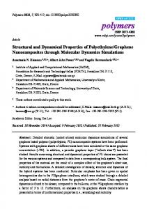
6, = rankG,(P,). The number and the choice of these 6, steering wheels is obviously a privilege of the robot designer. If a mobile robot is equipped with more than 6,conventional I/ //I centered orientable wheels (i.e., N , > 6,), the motion of the extra wheels must be coordinated to guarantee the existence of the Instantaneous Center of Rotation at Fig. 5. Instantaneous center of rotation. each time instant. It follows that onlyjve nonsingular structures are of pracW ) iE J w w c ) l . (15) tical interest and such that: , satisfies the following inequal1) the degree of mobility 6 Obviously rank [CT(Pc)] 5 3. If rank [CT(Pc)] = 3, then ities: R(6’)i = 0 and any motion in the plane is impossible! More generally, the limitations of the mobility of the robot are 15 6, 5 3. (16) related to the rank of Cy. This point will be discussed in detail hereafter. (The upper bound is obvious. The lower ound means that Before that, it is important to notice that conditions (12) we consider only the case where a motion is possible, and (13) have an interesting geometrical interpretation. At i.e., 6 , # 0.); each instant the motion of the robot can be viewed as an 2) the degree of steeribility 6, satisfies the following ininstantaneous rotation around the instantaneous center of roequalities: tation (ICR) whose position with respect to the frame can be time-varying. Hence at each instant the velocity vector of any 0__ 2 ) . If there are more than 2 centered wheels, their orientations must be coordinated in such a way that rank Cl,(P,) = 6, = 2 . The velocity [ ( t ) is constrained to belong to a one-dimensional distribution parametrized by the orientation angles of two arbitrarily chosen conventional centered orientable wheels of the robot, A typical example is the KLUDGE robot ([161).
51
Xl
Fig. 6. Omnidirectionnal robot-Type
(3,O). Three sweedish wheels.
have been presented above. We restrict our attention to robots with three wheels. As we have shown in Section 11-B, the wheels of a mobile robot are described by (at most) six characteristic constants: 1) three angles a , ,f3, y;and 2) three lengths I, T , d. For each example, we give successively a table with the numerical values of these characteristic constants and a presentation of the various matrices J and C involved in the mathematical expresions (10) and (11) of the constraints. However, we shall assume that the radii T and the distances d are identical for all the wheels of all the examples. Hence, we will specify only the values of a , p, y, 1. Example 1: Omnidirectional Robots with Swedish Wheels (Type (3,O)): The considered robot (see Fig. 6) has three Swedish wheels located at the vertices of the frame that has the form of an equilateral triangle (see for instance, [l]): Wheels lsw 2sw 3sw
P
a 4 3
1
7 0
0
L L L
0
lr
0
5lr/3
0
The constraints have the form (10) where
($ E), &
51 = [JlSw] =
$
L
-+l
52
= diag(r).
Example 2: Omnidirectional Robots with Off-Centered Orientable Wheels (Type (3,O)): The robot has three conventional off-centered orientable wheels as shown in Fig. 7. The constraints have the form (10) and (11) where
= [Jloc(Po,)] - sin P o c l sin Pocz cos Po& 52 = diag(r) J1
=(
cos P o c l - cos Paca
sin Poc3
L cos P o d L cos Paca L cos poc3
c1 = [ c l o c ( P O c ) l 111. EXAMPLES We present in this section six concrete examples of mobile robots .to illustrate the five types of nonsingular structures that
=
sin Pocl d + L sin PoCl cos Pocl - cos POcz - sin Poc2 d + L sin Paca
(
sin POc3 - cos Docs CZ= [CzOc] = diag ( d ) .
d
+ L sin
POc3
EEE TRANSACTIONS ON ROBOTICS AND AUTOMATION, VOL. 12, NO. 1, FEBRUARY 1996
52
Fig. 9. Robot of Type (2,l).
c 2 =
Fig. 7. Omnidirectional robot-Qpe wheels.
(3,O). Three off-centered orientable
t).
We note that the nonslipping constraints of to the 2 fixed wheels are equivalent (see the first 2 rows of Cl). Hence, the matrix Cy has a rank equal to 1 as expected. Example 4: Type (2,l): Robot with one conventional centered orientable wheel and two conventional off-centered orientable wheels, Fig. 9.
Fixed
Fig. 8. Robot of Type (2,O).
The constraints have the form (10) and (11) where
P
Wheels loc 20c
0
-
7r
-
30C
3n/2
-
a
1
L L
L
Example 3: Type (2,O): Robot with two conventional fixed wheels on the same axle and one conventional off-centered orientable wheel, Fig. 8. Wheels
a!
If 2f
P
0
0
?r
0
I L L
3oc
3n/2
-
L
The constraints have the form (10) and (11) where
J1
=
(2)
Example 5: Type (1,l): Robot with two conventional fixed wheels on the same axle and one conventional centered orientable wheel (like the tricycles of the kids), Fig. 10. Wheels
o!
P
1
If
0
L
2f 3c
?r
0 0
3~/2
-
L L
The constraints have the form (10) and (1 1) where cl
= =
(2TC)
[
1 -1 sin POc3
0 0 - cos POc3
d
+
0 0 L sin P O c 3
=[
0
1
0 -1 cos Pc3 sin P c 3
L cos p c 3
CAMPION et al.: STRUCTURAL PROPERTIES AND CLASSIFICATION OF ROBOTS
53
Iv. l%E
POSTURE KINEMATIC MODEL
In this section, the analysis of the mobility, as discussed in Section 11-C, is reformulated into a state space form which will be useful for our subsequent developments. We have shown (see (15)) that, whatever the type of mobile robot, the velocity ( ( t )is restricted to belong to a distribution A, defined as
( ( t )E A, g span {col RT(6)C(P,)}
Vt
where the columns of the matrix E(@,) form a basis of
~JIC,*(Pc>l:
Fig. 10. Robot of Type (1,l).
N J[CY
(PC)]
Stwrina "
This is trivially equivalent to the following statement: for all t, there exists a time varying vector q(t) such that
i= RT(W(PC>rl.
2
= diag(r)
c1=
c 2
( = RT(6)Cq.
(2)
=
(23)
The dimension of the distribution A, and hence of the vector q ( t )is the degree of mobility 6 , of the robot. Obviously, in the case where the robot has no conventional centered orientable wheels (6, = O), the matrix C is constant and the expression (23) reduces to
Fig. 11. Robot of Qpe (1,2).
52
= span{COlC(PC)1
(
1 0 -1 0 sin PC3 - cos Pc3
(24)
In the opposite case (6, 2 1),the matrix C explicitely depends on the angular coordinates Pc and the expression (23) can be augmented as follows:
i = RT(6)C(Pc)17 = s.
L sin PC3
= 0.
Pc
Example 6: Type (1,2): Robot with two conventional centered orientable wheels and one conventional off-centered orientable wheel, Fig. 11, Wheels
a
P
0
-
1
IC
2c 3oc
R
-
3~/2
-
L L L
The constraints have the form (10) and (11) where
(25) (26)
This representation (24) or (25) and (26) can be regarded as a state space representation of the system (called the posture kinematic model), with the posture coordinates E and (possibly) the angular coordinates Pc as state variables while q and (that are homogeneous to velocities) can be interpreted as control inputs entering the model linearly. This interpretation must however be taken with some care since the true physical control inputs of a mobile robot are the torques provided by the embarked motors: the kinematic state space model is in fact only a subsystem of the general dynamical model that will be presented in Section VI. In the next subsections we derive the posture kinematic models corresponding to the examples of Section 111, and show that these models are generic and irreducible. This will allow to discuss the controllability and the stabilizability of the posture kinematic models of all WMR.
A. The Five Generic Models of Wheeled Mobile Robots We rewrite the posture kinematic model in the following compact form:
i = B(z)u
with either (when N , = 0)
z g t B ( z )g P ( 6 ) C u g q
(27)
IEEE TRANSACTIONS ON ROBOTICS AND AUTOMATION, VOL. 12, NO 1, FEBRUARY 1996
54
TABLE I THE 5 GENERICPOSTURE KLNEMHTCMODELSOF WHEELEDMOBILEROBOTS
or (when N ,
2
0)
We give in Table I the particular form of z , C(Pc)or C and the equations of the posture kinematic models for the examples that have been presented in Section III. A natural question arises: for each class of WMR, is this posture kinematic model generic for all the robots belonging to this class ? The answer is affirmative: for any nondegenerate robot it is always possible to select the reference point P and the basis {xi,x i } attached to the robot frame in such way that the posture kinematic model takes exactly the form corresponding to the type of the robot, as given in Table I, as follows. For a Type (3,O) robot, the reference point P and the basis {xi,&} can be chosen arbitrarily. For a Type (2,O) robot, P is chosen as a point of the axle of the fixed wheels, with & aligned along this axle. See, for example, Fig 8. For a Type (2,l) robot, we select one of the centered wheels and P is choosen as the center of this wheel, with { x i , x>} chosen arbitrarily. See, for example, Fig 9. For a Type (1,l) robot we select one of the centered wheels. P is the foot of the perpendicular drawn, from the center of the selected centered wheel onto the common axle of the fixed wheels. L is the length of this perpendicular. See, for example, Fig 10. For a Type (1,2) robot, we select 2 centered orientable wheels. P is chosen as the mid-distance point between the centers of these 2 wheels, with xi aligned along the line joining their centers; L is the half distance between these centers. See, for example, Fig 11.
B. Mobility, Steeribility, and Maneuverability This kinematic posture model allows to discuss further the , is a first maneuverability of WMR. The degree of mobility 6 criterion of the maneuverability: it is equal to the number of degrees of freedom that can be directly manipulated from the inputs q, without reorientation of the centered wheels. Intuitively, it corresponds to how many “degrees of freedom” the robot could have instantaneously from its current config, is not uration, without steering any of its wheels. This 6 equal to the overall number of “degrees of freedom” of the robot that can be manipulated from the inputs 7 and C. In , 6, that fact this number is equal to the sum SM = 6 we could call degree of maneuverability. It includes the 6, additional degrees of freedom that are accessible from the inputs 5. But the action of 5 on the posture coordinates is indirect, since it is achieved only through the coordinates 3 /, that are related to 5 by an integral action. This reflects the fact that the modification of the orientation of a centered wheel can not be achieved instantaneously. The maneuverability of a WRM depends on S M , but also on the way how these SM degrees of freedom are partitionned into 6 , and 6,.Therefore 2 indices are needed to characterize the maneuverability: SM and ,S or, equivalently, 6 , and S,, which are the 2 indices identifying the five classes of robots in Table I. Two robots with the same value of S M , but different ,S are not equivalent. For robots with 6 , = 3, it is possible to freely assign the position of the ICR, either directly from 7 , for the Type (3,O) robots, or by orientation of 1 or 2 centered wheels for the Type (2,l) and (1,2) robots. For robots with SM = 2, the ICR is constrained to belong to a straight line (the axle of the fixed wheel). Its position on this line is assigned either directly for Type (2,O) robots, or by the orientation of a centered wheel for Type (1,l) robots.
+
CAMPION et al.: STRUCTURAL PROPERTIES AND CLASSIFICATIONOF ROBOTS
Similarly, two WRM with the same value of ,S but different S M , are not equivalent: the robot with the largest SM is more manoeuvrable. Compare, for instance, a Type (1,l) and a Type (1,2) robots, with 6, = 1, and, respectively, SM = 2 and 6~ = 3. The position of the ICR for the Type (1,2) robot can be assigned freely in the plane, just by orienting 2 centered wheels, while for the Type (1,1), the ICR is constrained to belong to the axle of the fixed wheels, its position on this axle being specified by the orientation of the centered wheel. Since the steering directions of the centered wheels can usually be changed very quickly, especially for small indoor robots, it results, from a practical veiwpoint, that the Type (1,2) robot is more manoeuvrable than the Type (1,l). Obviously, the ideal situation is that of omnidirectional , = SM = 3. robots where 6
55
+
We see that rank B (x) = 6 , 6, = 2 and dim A(.) = dimx = 4 everywhere in the state space. It follows that the kinematic state space model (28) of a robot of Type (1,l) is irreducible. Furthermore, the same line of reasoning that has been followed for Type (1,l) can be followed easily for any Type of mobile robot. It appears that all posture kinematic models of Table I are irreducible. We summarize this analysis in a Property. Property 1: 1) For the posture kinematic model i = B ( z ) uof wheeled mobile robots: a) the input matrix B(x) has full rank: rank B ( x ) = ,S
A(z) k span{col(B(x))}. It is a well known consequence of Frobenius Theorem that the system is reducible only if d i m A < dimz. In this section, we shall prove that the posture kinematic model of nondegenerate mobile robots (see Assumption A2) is always irreducible. To establish this result, we proceed by first analyzing in details the particular case of the robot of Type (1,1) whose posture kinematic model is as follows (see Table I):
for all z .
b) the involutive distribution A@) A inv span {col B ( z ) }has constant maximal dimension:
C. Irreducibility of the Posture Kinematic Model In this section, we address the question of the reducibility of the posture kinematic model (27). A state space model is reducible if there exists a change of coordinates such that some of the new coordinates are identically zero along the motion of the system. For a nonlinear dynamical system wihout drift like (27), the reducibility is related to the involutive closure A of the following distribution A, expressed in local coordinates as:
+ S,
dimA(x) = 3
+ 6,
for all z.
2) Consequently, the posture kinematic model of wheeled mobile robots is irreducible. This is a coordinate free property. U
D. Controllability, Feedback Linearizability, and Stabilizability In this section, we summarize the main controllability and feedback stabilizability properties of the posture kinematic model of wheeled mobile robots. We first examine the linear approximation around an arbitrary equilibrium state 2 4 ([, De). Equilibrium means that the robot is at rest somewhere, with a given constant posture f and a given constant orientation pc of the orientable centered wheels. Obviously, the velocities are zero: fi = 0. Property 2: The controllability rank of the linear approximation of the posture kinematic model i = B ( z ) u around an 6,. equilibrium state is 6, Indeed, the linear approximation around ( Z , G = 0) is written: d - ( z - z)= B(2)u. dt
+
Y
t
Bb)
In this particular case, a basis of
A(.)
is as follows:
A(x) = sPan{bl(x), b2(x), b 3 ( z ) ,b4(x)) with bl ( z ),b2 (2) the columns of B( z ) :
It follows that the controllability matrix reduces to B(2)whose U rank is ,S Ss for all Z by Property 1. This implies that the linear approximation of the posture kinematic model of omnidirectional robots (Type (3,O)) is , is precisely the state dicompletely controllable since 6 mension in this case while it is not controllable for restricted mobility robots (Types (2,0), (2,1), (l,l), (1,2), 6, .,) (43) [TIP, = (44
In the general configuration dynamical model (45)-(50), the vectors ~ ~ ,andr re~ represent ~ , all the torques that can potentially be applied for the rotation and the orientation of the wheels of the robot. In practice, however, only a limited number of motors will be used, which means that many and rc are identically zero. components of ry,roc, Our concern in t h s section is to explicit the configurations of the motorization that allow a full maneuverability of the robots while requiring a number of motors as limited as possible. First, it is clear that all the centered orientable wheels must be provided with a motor for their Orientation (otherwise, these wheels would just play the role of fixed wheels). Moreover, to ensure a full robot mobility, "additional , 6 must be implemented for either the motors (with N, 2 ) rotation of some wheels or the orientation of some off-centered orientable wheels. The vector of the torques developed by these motors is denoted r, and we have
with the compact notation a d
aT
dt
a+
[TI+= -(-)
-
= Pr,
dT
-.
a$
The kinetic energy of wheeled mobile robots can be expressed as follows:
+
T = i T R T ( ~ ) [ M ( P o c ) R ( ~2 v)(ip o c ) b o c
+ B o c ~ o c P o c+ 'pI,'p +
+
a w b c ]
+
where P is a (Noc I?) x N , elementary matrix which selects r,) that are effectively used as control the components of (roc, inputs. Using (51) we see that (48) of the general dynamical model is rewritten as
BCICBC
+
~l(PC,POC)+ ~ T ( P c ) v ( P o c ) i+ fl(Pc, Po,, v,5) with appropriate definitions of the matrices M(,BOc), V(Poc), W,Io,,,I,, I, which are dependent of the mass = B(Pc, P0c)PTm distribution and the inertia moments of the various rigid bodies (frame and wheels) that constitute the robot. The with B(Pc,Po,) A CT(P,)[DT(Poc) ET(Pc,Poc)l. We introduce the following assumption. state equations for 7 and C are then obtained (after rather A3: The configuration of the motorization is such that the lenghty calculations) by substituting this expression of T in the dynamical equations (43) and (44) and eliminating matrix (2j, jC the velocities ,&, 'p, ,bc and the accelerations w e , POJP with the aid of the kinematic equations (25), (26), (31), (32), and their derivatives. The general dynamical state space model of wheeled mobile has full rank for all (Pc,pot) E R N c t N o c . We now present the minimal admissible motorizations for robots then takes the following general form: the various types of mobile robots that have been described General configuration dynamical model: in the Section III. i = R'(e)c(Pc)rl (45) w p e (3,0)-Example 1 (Fig. 6). Omnidirectionnal robot Bc = 5 (46) with three Swedish wheels.
6,
i,Bo,,
CAMPION et al.: STRUCTURALPROPERTIES AND CLASSIFICATIONOF ROBOTS
In this case, the matrix B is constant and reduces to
59
The corresponding selection matrices P are as follows:
which is nonsingular. We conclude that the only admissible motorization is to equip each wheel with a motor. Type (3,O)-Example 2 (Fig. 7). Omnidirectionnal robot with three off-centered orientable wheels. In this case the matrix B(Poc)is written as follows:
B(Poc)= xT[oT(Poc) ET(Poc)]with CTDT(Poc)= cos P o c l - cos Poc2 sin P o c 3 - sin P o c z - cos Doc3 d L sin Poci d L sin Poc2 d L sin Poc3 with CTET(Poc)=
+
+
- sinPOcl
+
sinPoc2
cosPoc3
b, p =
[i 8)
Type (2,l)-Example 4 (Fig. 9). Robot with one centered orientable wheel and two offcentered orientable wheels. In this case, we first need a first orientation motor for the centered orientable wheel. The matrix B J ( P c ,Po,) is then written as follows: B(Pc, D o c ) = CT(Pc)[DT(Poc)
It appears that there is no set of 3 columns of B(Poc) which are independent for any (PoCl,Paca, P o c 3 ) . It is therefore necessary to use (at least) N , = 4 motors. An admissible configuration is as follows: 2 motors (one for the orientation and one for the rotation) on 2 of the 3 wheels (the third one being not motorized and hence self-aligning). For instance, if the wheels 1 and 2 are motorized in this way, the selection matrix P is as follows:
P=
1 0 0 0 0 0
1
0 1 0 0 0 0
0 0 0 1 0 0
0 0 0 0 1 0
and the matrix B(&)P has full rank (= 3) for any configuration of the robot. Type (2,O)-Example 3 (Fig. 8). Robot with two fixed wheels and one off-centered orientable wheel. The matrix B(Poc)is written
with
xT(pc)=
and c) 2 motors (orientation and rotation) on the offcentered wheel 3, provided d < L.
Poc)]
-1
- cos Poca sin Poc2
d
+ LsinPocl d + LsinPoca - sin Pocl L sin Po,-:!
COS Pc3
cos PoCl L cos P o c l
- cos POc2
L cos Poca
The columns 1 and 3 of B(PC, Doc) are independent if d > L A . The same holds for columns 2 and 3. Hence two admissible motorizations are obtained by using a second motor for the rotation of the centered wheel (number 3) and a third motor for the orientation of either wheel 1 or wheel 2. The two corresponding matrices P are:
1)P=
( li) ( i) 0
1
2)P=
0
1
.
Type (1,l)-Example 5 (Fig. 10). Robot with two fixed wheels and one centered orientable wheel. A first orientation motor for the centered orientable wheel is needed. The matrix B(Pc)reduces to the vector
B = [sinPC3 Several configurations with 2 motors are admissible: a) 2 rotation motors on wheels 1 and 2: b) 1 motor for the orientation of wheel 3 and one for the rotation of wheel 2 (or 3), provided d > L$;
@(Pc,
+ cos
Pc3
- sin Pc3 + cos pc3 11.
Since 6 , = 1, A3 will be satisfied if a second motor is provided for the rotation of the third wheel. The matrix P is written:
P=
(H).
EEE TRANSACTIONS ON ROBOTICS AND AUTOMATION, VOL. 12, NO. 1, FEBRUARY 1996
60
6 (Fig. 11). Robot with two centered orientable wheels and one offcentered orientable wheel. Two motors are required for the orientation of the two centered wheels. The matrix B(pc,Doc) is written as
* Type (1,2)-Example
B(DC,
Doc)
= “c)[DT(Poc)
-2L sin with C(Pc) =
ET(Dc,Poc)l
sin Pc2
+
sin(Pc1 P c z ) 2 sin Pc2 cos Pel - sin(Pcl
+ PCz)
-1 - Ld-’ sin pOc3
cos pCz sin Doc3
L cos Pel L cos pcz L cos Docs
)
.
Since 6 , = 1, it would be sufficient to have one column of B(& Doc) being nonzero for all the possible configurations. However, there is no such column. It is therefore necessary to use 2 additional motors, for instance for the rotation of wheels 1 and 2 giving the matrix P
It results from Assumption A3 that the matrix F ( P ) has full ra.nk for all ,B. This property is important to analyze the behavior of wheeled mobile robots and the design of feedback controllers. It is first used to transform the general state space model into a simpler and more convenient form, by a smooth static state feedback. Property 7: The configuration dynamical model of wheeled mobile robots ((52) and (53)) is feedback equivalent (by a smooth static time-invariant state feedback) to the following system:
(54)
(55) where U represents a set of 6 , auxiliary control inputs. Indeed it foIlows readily from Property 1 that the following smooth static time invariant state feedback is well defined everywhere in the state space:
/o o \ where Ft denotes an arbitrary left inverse of F ( P , U ) . R We would like to emphasize that a further simplification is of interest from an operational viewpoint. In a context of trajectory planning or feedback control design, it is clear that the user will be essentially concerned by controlling the posture of the robot (namely the coordinate E(t)) by using the control input U. We observe that this implies that we can ignore deliberately the coordinates POcand p and restrict our attention to the following posture dynamical model. Posture dynamical model:
Finally the following table summarizes the results:
i = B(z)u
VII. THE POSTURE
DYNAMICAL
,&=U
MODEL
where we recall that z i? and U a (7,C)T. This posture dynamical model fully describes the system dynamics between the control input U and the posture E, The (52) coordinates Doc and cp have apparently disappeared but it is (53) important to notice that they are in fact hidden in the feedback (56). The difference with the posture kinematic model is that now the variables U are part of the state vector. This implies the existence of a drift term and the fact that the input vector fields are constant. The posture dynamical model inherits of the structural properties of the posture kmematic model discussed in Section N-C. Property 8: a) The posture dynamical model is generic and irreducible. b) The posture dynamical model is Small-Time-LocallyControllable. c) For restricted mobility robots, the posture dynamical model is not stabilizable by a continuous static time
The configuration dynamical model of wheeled mobile robots can be rewritten in the following more compact form:
with the following definitions:
ua
(;)
CAMPION et al.: STRUCTURAL PROPERTIES AND CLASSIFICATIONOF ROBOTS
invariant state feedback, but is stabilizable by a time varying static state feedback. d) The dimension of the largest feedback linearizable subsystem of the posture dynamical model by static state feedback is 2(6, 6,). Omnidirectional robots are therefore state feedback linearizable. e) The posture dynamical model is a differentially flat system.
+
VIII. CONCLUSION
It has been shown that, according to the restriction to the mobility induced by the kinematic constraints, all WMR can be classified into 5 categories, with particular structures of the corresponding kinematic and dynamic models. Four models have been introduced. - The posture kinematic model (Section IV), which is sufficient to describe the global motion of the robot. This model is generic in the sense that all the robots belonging to the same class are described by the same posture kinematic model. - The conjiguration kinematic model (Section V ) describing the evolution of all the configuration variables. - The configuration dynamical model (Section VI) taking account the dynamics of the robot, including the torques provided by the motors - The posture dynamical model (Section VII), which is feedback equivalent to the configuration dynamical model. The equations of this model can be obtained from the posture kinematic model just by adding one integrator on each input. The inputs of the kinematic models are homogeneous to velocities, while the inputs of the dynamical models are either torques or accelerations. The posture models are generic, irreducible, and controllable; they are sufficient for posture control purpose. The configuration models are nongeneric, reducible, and not controllable; they depend on the particular structure of the robot and allow to describe the evolution of all the configuration variables.
ACKNOWLEDGMENT
61
[5] E. Badreddin and M. Mansour, “Fuzzy-tunedstate-feedbackcontrol of a nonholonomic mobile robot,” in IFAC World Congr., Sidney, Australia, 1993, pp. II 212-215. [6] R. M. Murray and S . S . Sastry, “Nonholonomic motion planning: Steering using sinusoids,” IEEE Trans. Automat. Contr., vol. 38, pp. 700-716, May 1993. [7] P. Rouchon, M. Fliess, J. Uvine, and P. Martin, “Flatness and motion planning: The car with n trailers,” in Proc. European Control Con$ 93, Groningen, The Netherlands, pp. 1518-1522. [8] J. B. Pomet B. Thuillot, G. Bastin, and G. Campion, “A hybrid strategy for the feedback stabilization of nonholonomic mobile robots,” in IEEE Int. Con$ Robotics and Automation, Nice, France, 1992, pp. 129-135. [9] P. F. Muir and C. P. Neuman, “Kinematic modeling for feedback control of an omnidirectional wheeled mobile robot,” in Proc. IEEE Con$ Robotics and Automation, 1987, pp. 1772-1778. [lo] S. M. Killough and F. G. Pin, “Design of an omnidirectional and holonomic wheeled platform design,” in Proc. IEEE Con$ Robotics and Automation, Nice, France, 1992, pp. 84-90. [ I l l B. d’Andr6a-Nove1, G. Bastin, and G. Campion, “Modeling and Control of nonholonomic wheeled mobile robots,” in Proc. IEEE Con& Robotics and Automation, Sacramento, CA, 1991, pp. 1130-1135. [12] P. F. Muir and C. P. Neuman, “Kinematic modeling of wheeled mobile robots,” J. Robotic Syst., vol. 4, no. 2, pp. 281-329, 1987. [13] J. C. Alexander and J. H. Maddocks, “On the kinematics of wheeled mobile robots,” Int. J. Robotics Res., vol. 8, no. 5, pp. 15-27, 1989. [14] C. Helmers, “Ein Hendenleben, (or, A hero’s life),” Robotics Age, vol. 5, no 2, pp. 7-16, Mar. 1983. [15] C. Balmer, “Avatar: A home built robot,” Robotics Age, vol. 4, no 1, pp. 20-25, Jan. 1988. [16] J. M. Holland, “Rethinking robot mobility,” Robotics Age, vol. 7, no 1, pp. 26-30, Jan. 1988. [I71 H. Nijmeijer and A. J. Van der Schaft, Nonlinear Dynamical Control Systems. New York Springer-Verlag, 1990. [IS] A. Isidori, Nonlinear Control Systems. Berlin: Springer-Verlag 1989. [19] R. Marino, “On the largest feedback linearizable subsystem,” Syst. Contr. Lett., vol. 6, pp. 345-351, 1986. [20] P. Martin, “ContributionB I’btude des systkmes diffkrentiellement plats,” Ph.D. Thesis, Ecole Nationale Supkrieure des Mines de Paris, 1992. [21] B. d’Andr6a-Novel, Campion G., and Bastin G., “Control of nonholonomic wheeled mobile robots by state feedback linearization,”to appear in J. Robotics Res. [22] R. W. Brockett, “Asymptotic stability and feedback stabilization,” in Differential Geometric Control Theory, R. W. Brockett, R. S. Millmann, and H. J. Snssmann, Eds. Boston: Birkhauser, 1983, pp. 181-191. [23] J. M. Coron, “Global asymptotic stabilization for controllable systems without drift,” M.C.S.S. vol. 5, pp. 295-312, 1992. [24] J. B. Pomet, “Explicit design of time-varying stabilizing control laws for a class of time varying controllable systems whithout drift,” Syst. Contr. Lett., vol. 18, pp. 147-158, 1992. [25] G. Campion, B. d’Andr6a-Nove1, and G. Bastin, “Controllability and state feedback stabilization of nonholonomic mechanical systems,” Advanced Robot Control, Lecture Notes in Control and Information Sciences, no. 162, pp. 106-124, 1990. [26] A. M. Bloch, N. H. McClamroch, and M. Reyhanoglu, “Control and stabilization of nonholonomic dynamic systems,” IEEE Trans. Automat. Contr., vol. 31, pp. 1746-1757, 1992. [ U ] G. Campion, B. d’Andr6a-Novel, and G. Bastin, “Modeling and state feedback control of nonholonomic mechanical systems,” in IEEE Con$ Decision and Control, Brighton, England, 1991, pp. 1184-1189.
This paper presents research results of the Belgian Programme on Interuniversity Poles of Attraction, initiated by the Belgian State, Prime Minister’s Office for Science, Technology and Culture. The scientific responsibility rests with its authors. REFERENCES [ 11 G. Bastin and G. Campion, “On adaptive linearizing control of omni-
directional mobile robots,” in Proc. MTNS 89, Progress in Systems and Control Theory 4, Amsterdam, vol. 2, pp. 531-538. [2] C. Samson and K. Ait-Abderahim, “Feedback control of a nonholonomic wheeled cart in Cartesian space,” in Proc. 199I IEEE Int. Con$ Robotics and Automation, Sacramento, CA, Apr. 1991, pp. 1136-1141. [3] C. Canudas de Wit and 0. J. Sordalen, “Exponential stabilization of mobile robots with nonholonomic constraints,” in IEEE Con$ Decision and Control, Brighton, England, Dec. 1991, pp. 692-697. [4] J. P. Laumond, “Controllability of a multibody mobile robot,” ICAR, Pisa, Italy, 1991, pp. 1033-1038.
Guy Campion received the mechanical engineering and the Ph.D. degrees, both from Universitk Catholique de Louvam, Louvain-la-Neuve, Belgium. Since 1977 he has been Research Associate (Fonds National de la Recherche Scientifique) with the CESAME (Centre for Systems Engiueenng and Applied Mechanics) at the same University. His m a n research interests are in nonlinear control theory, and modeling and control of mechanical systems.
62
IEEE TRANSACTIONS ON ROBOTICS AND AUTOMATION, VOL. 12, NO. 1, FEBRUARY 1996
Georges Bastin received the electrical engineering and the Ph.D. degrees, both from Univeisit6 Catholique de Louvain, Louvain-la-Neuve, Belgium. He is currently Professor in the Center for Systems Engineering and Applied Mechanics (CESAMJZ) at the Universiti Catholique de Louvain. His main research interests are in system identification, nonlinear control theory, adaptive systems, and random fields with applications to mechanical systems and robotics, biological processes, transportation systems, and environmenal problems.
Brigitte D’AndrCa-Novel was bom in Villempt, France, in 1961 She graduated from the Ecole Supineure d’hfomahque, Electromque, Automatique, France, in 1984 She received her Docteur degree from the Ecole des Mines de Pans in 1987 and her Habihtahon degree from the Umversity of Pans XI, Orsay, in 1995 Presently, she is Professor of Systems Control Theory at the Ecole des Mines de Pans, and is also responsible for a research group on mechanical systems at the Centre d’Automatique et Systkmes of Ecole des Mines de Pans Her current research interests are in nonlinear control theory and its applications to under-actuated mechmcal systems, mobile robots, and mazhanical systems with flexibilities