Structure and properties of reactive direct current magnetron sputtered niobium aluminum nitride coatings Harish C. Barshilia,a) B. Deepthi, and K.S. Rajam Surface Engineering Division, National Aerospace Laboratories, Bangalore 560 017, India
Kanwal Preet Bhatti and Sujeet Chaudhary Department of Physics, Indian Institute of Technology, New Delhi 110 016, India (Received 24 September 2007; accepted 20 December 2007)
A reactive direct current magnetron sputtering system was used to prepare NbAlN coatings at different nitrogen flow rates and substrate bias voltages. Various properties of NbAlN coatings were studied using x-ray diffraction, scanning electron microscopy, atomic force microscopy, x-ray photoelectron spectroscopy, nanoindentation, the four-probe method, a solar spectrum reflectometer and emissometer, spectroscopic ellipsometry, micro-Raman spectroscopy, and potentiodynamic polarization techniques. Single-phase NbAlN with B1 NaCl structure was obtained for the coatings prepared at a nitrogen flow rate in the range of 1.5–3 sccm, a substrate bias voltage of −50 to −210 V, and a substrate temperature of 300 °C. Nanoindentation data showed that the optimized NbAlN coating exhibited a maximum hardness of 2856 kg/mm2. An approximately 100-nm-thick NbAlN–NbAlON tandem on copper substrate exhibited a high absorptance (0.93) and a low emittance (0.06), suitable for solar-selective applications. The spectroscopic ellipsometry and resistivity data established the metallic nature of NbAlN and the semitransparent behavior of NbAlON coatings. The corrosion resistance of NbAlN coatings was superior to that of the mild steel substrate. The addition of aluminum in NbN coatings increased the onset of oxidation in air from 350 to 700 °C. Vacuum-annealed NbAlN coatings were structurally stable up to 700 °C and retained their high hardness up to a temperature of 650 °C.
I. INTRODUCTION
Binary nitrides of transition metals such as TiN, CrN, or NbN have been explored to a great extent due to their excellent mechanical properties and resistance to chemical attack.1 NbN coatings exhibit a variety of interesting properties like high hardness, chemical inertness, and high electrical conductivity. At low temperatures, NbN becomes a superconductor and therefore finds applications in infrared imaging photodetectors, superconducting magnets, and other microelectronic devices.2,3 NbN coatings have also been used as cathode material for field emission in vacuum microelectronic devices.4 Nanolayered multilayer coatings based on NbN such as TiN– NbN5,6 or CrN–NbN7 have been found to exhibit improved mechanical and tribological properties compared to single-layer coatings. Recently, Nb–NbN multilayer films have been developed for solar-selective applications.8 a)
Address all correspondence to this author. e-mail:
[email protected] DOI: 10.1557/JMR.2008.0168 1258
J. Mater. Res., Vol. 23, No. 5, May 2008
Incorporation of additional elements like aluminum, silicon, or chromium into transition-metal nitride matrices has led to the formation of ternary nitrides with improved properties. TiAlN and CrAlN coatings, which have been widely studied, exhibit higher hardness and thermal stability when compared to TiN and CrN.9–11 On the other hand, NbAlN coatings have rarely been studied. The bonding structure is expected to change from metallic to covalent with the addition of aluminum in the NbN matrix. The properties of NbAlN therefore depend on the Al content of the films. In particular, the mechanical properties, chemical stability, and thermal stability of these coatings are expected to improve with the addition of aluminum. The change in the bonding structure also results in variations in the electrical resistivity and the optical properties of NbAlN. NbAlN coatings have a great potential for wearresistance applications such as machining tools and coated components, which are subjected to extremely high wear.12 These coatings may also find applications as barrier structures for electronic devices.13 However, various properties (mechanical, electrical, chemical, and optical) of sputter-deposited NbAlN coatings have not been © 2008 Materials Research Society
H.C. Barshilia et al.: Structure and properties of reactive direct current magnetron sputtered niobium aluminum nitride coatings
explored so far. Selinder et al.14 have briefly studied the phase formation and microstructure of sputter-deposited NbAlN coatings. The structural properties of nanocrystalline NbAlN powder synthesized by ball milling have been studied by Miki et al.15 II. EXPERIMENTAL DETAILS
A reactive direct current (dc) magnetron sputtering system was used to deposit NbAlN coatings on silicon (100), mild steel (MS) (composition 0.37 at.% C, 0.28 at.% Si, 0.66 at.% Mn, and 98.69 at.% Fe), and copper substrates. The sputtering system has been described in detail elsewhere.9 A NbAl (50:50) composite (purity 99.95%) target was sputtered in high-purity argon (99.999%) and nitrogen (99.999%) plasma. The coatings were deposited under a base pressure of 4.0 × 10⁻⁴ Pa and a total argon–nitrogen gas pressure of 4.0 × 10⁻¹ Pa. The flow rates of nitrogen (1–3 sccm) and argon (17 sccm) were controlled separately by mass-flow controllers. A dc substrate bias was applied to improve the mechanical properties of the coatings. The coatings were deposited at a substrate temperature of 300 °C. The power density for the NbAl target was approximately 2.26 W/cm2. The substrates were metallographically polished and then chemically cleaned in an ultrasonic agitator using isopropyl alcohol, trichloroethylene, and acetone. The root mean square (rms) roughness of the substrates after polishing was approximately 1.2 nm. Subsequently, the substrates were also cleaned in situ by argon ion bombardment for 30 min, wherein a dc bias of −850 V was applied to the substrate at an argon pressure of 6.0 × 10⁻¹ Pa. A Ti interlayer was deposited to improve the adhesion of the coatings for the samples used to study the structural and mechanical properties. The thickness of the NbAlN coating was approximately 1.5 m. To study the optical properties, a tandem of NbAlN–NbAlON with a total thickness of approximately 100 nm was deposited on copper substrates. Sputtering was carried out at a power density of 2.26 W/cm2 for both NbAlN and NbAlON coatings. The NbAlN coating was prepared from the reactive sputtering of a Nb–Al composite target in argon–nitrogen plasma at a nitrogen flow rate of 3.0 sccm, whereas the NbAlON coating was deposited using the same Nb–Al composite target in argon–nitrogen–oxygen plasma at nitrogen and oxygen flow rates of 2.0 and 1.5 sccm, respectively. X-ray diffraction (XRD) patterns of the coatings in thinfilm mode were recorded in a Rigaku (Japan) D/max 2200 Ultima x-ray powder diffractometer. The x-ray source was a Cu K␣ radiation ( ⳱ 0.15418 nm). X-ray photoelectron spectroscopy (XPS) was used to study the bonding structure of the coatings. The spectrum was recorded using a V.G. Microtech (UK) ESCA 3000 system with a monochromatic Al K␣ x-ray beam (energy 1486.5 eV;
power 150 W). The partial pressures of H2O and O2 in the deposition chamber were measured using an AccuQuad-100D (USA) residual gas analyzer (RGA). The elemental compositions of the coatings were determined using an Oxford (UK) energy-dispersive x-ray spectrometer (EDS) attached to a scanning electron microscope (SEM). The surface morphology of the coatings was studied using a Leo 440I (UK) SEM and a Surface Imaging Systems (Germany) atomic force microscope (AFM). A nanoindentation hardness tester (CSEM Instruments, Switzerland) was used to evaluate the hardness of the NbAlN coatings. The measurements were performed using a Berkovich diamond indenter at a load of 5 mN. At this load, the indentation depth (100–130 nm) was much less than one tenth of the film thickness, thus minimizing the effect of the substrate on the hardness measurements. Ten indentations were made on each sample, and the values reported herein represent the average of 10 measurements. The electrical resistivity of the coatings was calculated by in-plane four-probe I-V measurements using a Keithley (Cleveland, OH) 2400 Source Meter and a Keithley 2180A Nanovoltmeter. The optical properties [i.e., absorptance (a) and emittance (⑀)] of the NbAlN coatings were measured using a solar spectrum reflectometer and emissometer (M/s. Devices and Services). The optical constants [refractive index (n) and extinction coefficient (k)] of the films were measured in a phase-modulated spectroscopic ellipsometer (model UVISEL 460; ISA JOBIN-YVON-SPEX) in the wavelength range of 300–1200 nm. The thermal stability of NbAlN was studied by heating the films in air in a resistive furnace at temperatures in the range of 300–800 °C. The details of the heat treatment have been described elsewhere.10 The samples were also annealed in a vacuum (approximately 4.0 × 10⁻⁴ Pa) at temperatures in the range of 400–700 °C for 30 min under identical heating and cooling rates. The structural changes and hardness of the films as a result of heat-treatment were measured using micro-Raman spectrometer and nanoindentation, respectively. A DILORJOBIN-YVON-SPEX (France) integrated micro-Raman spectrometer was used for the present study. The corrosion behavior of the coatings was studied using the potentiodynamic polarization method in a 3.5% NaCl solution under free-air conditions at room temperature. The corrosion potential (Ecorr), the corrosion-current density (icorr ), and the polarization resistance (Rp ) were deduced from the Tafel (log i versus E) plots. III. RESULTS AND DISCUSSION A. Structural properties
Niobium nitride exists in different phases, such as -Nb2N, ␥-Nb4N3, or ␦-NbN.15 The cubic phase of ␦-NbN with a B1 NaCl structure exists in a limited range
J. Mater. Res., Vol. 23, No. 5, May 2008
1259
H.C. Barshilia et al.: Structure and properties of reactive direct current magnetron sputtered niobium aluminum nitride coatings
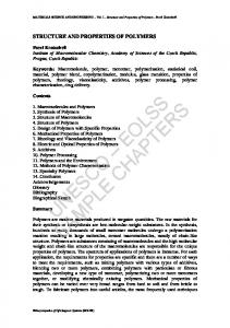
of nitrogen concentrations. It is believed that the nitrogen concentration affects the stoichiometry and crystal structure of NbAlN coatings. To achieve single-phase cubic NbAlN coatings (with B1 NaCl structure), deposition parameters such as target power density, nitrogen flow rate, substrate temperature, and substrate bias voltage, were optimized in the present study. In the following section, we present the XRD data of NbAlN coatings prepared at different substrate bias voltages and nitrogen flow rates. The XRD patterns of NbAlN coatings deposited at different substrate bias voltages are shown in Fig. 1. The nitrogen flow rate for this set of experiments was 2.5 sccm. All the coatings exhibited (111) and (200) reflections. The x-ray intensities of other higher angle reflections, such as (311) and (220), were very low. For the NbAlN coatings, significant changes were observed in the XRD patterns with an increase in the bias voltage. The interplanar spacings and the full width at halfmaximum (FWHM) values for the NbAlN coatings prepared at various bias voltages are shown in Table I. At a bias voltage of −50 V, reflections of (111) and (200) planes of cubic NbAlN were observed at 2 values of 35.99° and 41.84°, respectively. The assignment of these
FIG. 1. XRD patterns of NbAlN coatings deposited at different bias voltages, with a nitrogen flow rate of 2.5 sccm and a substrate temperature of 300 °C. 1260
TABLE I. XRD data of NbAlN coatings deposited at different bias voltages. (111) Bias voltage (V)
2 (deg.)
−50 −130 −210
35.99 35.43 35.31
(200)
d (Å)
FWHM (deg.)
2 (deg.)
d (Å)
FWHM (deg.)
2.49 2.53 2.54
0.40 1.09 1.87
41.84 41.15 41.14
2.16 2.19 2.19
1.04 1.31 2.37
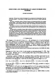
reflections was performed based on the Joint Committee on Powder Diffraction Standards file for cubic NbN [2 ⳱ 35.39 and 41.10°, respectively, for (111) and (200) reflections].16 There was a considerable shift in the 2 values of the (111) and (200) peaks toward lower angles with an increase in the bias voltage (Table I). The shift can be attributed to higher residual stresses and changes in the composition of the coatings. An increase in the residual stress with increasing bias voltage is commonly observed in bias-sputtered transition-metal nitride films. This is due to the increased energy of the bombarding ions (Ar+), resulting in higher defect concentrations.17 Residual compressive stresses tend to shift the diffraction peaks to higher d values.18 The average lattice parameter calculated for NbAlN coatings was 0.4364 nm, which is close to the lattice parameter reported for nanocrystalline NbAlN powder (0.4293 nm).15 The effect of composition on the stress of nitride coatings will be discussed later. In addition to the shift, a broadening of the diffraction peaks was observed with an increase in the substrate bias voltage. This is due to the fact that, at higher bias voltages, the increase in point defects (due to the higher ion energy) provides additional preferential sites for nucleation, which results in a decrease in the grain size.19 The ion current densities at bias voltages of −50 and −210 V were 0.27 and 0.45 mA/cm2, respectively. The determination of the crystallite size of the NbAlN coatings using the Debye–Scherrer formula20 indicated an average crystallite size of approximately 22 nm at −50 V, which decreased to about 5 nm at a bias voltage of −210 V. It is to be noted that contribution due to the microstrain on the broadening of XRD profiles has not been considered while calculating the crystallite size using the method described above. Figure 2 shows the XRD data of NbAlN films deposited at different nitrogen flow rates. A substrate bias voltage of −210 V was applied for this set of experiments. The analysis of the XRD data is given in Table II. At a nitrogen flow rate of 1 sccm, in addition to (111) and (200) reflections, the XRD data showed the presence of a low-intensity peak at 31.75°, which disappeared at higher nitrogen flow rates. This peak may be attributed to the (004) reflection of hexagonal Nb2AlN.21 At a nitrogen flow rate of 3 sccm, the intensity of the diffraction
J. Mater. Res., Vol. 23, No. 5, May 2008
H.C. Barshilia et al.: Structure and properties of reactive direct current magnetron sputtered niobium aluminum nitride coatings
FIG. 2. XRD patterns of NbAlN coatings deposited at different nitrogen flow rates, maintaining a bias voltage of −210 V and a substrate temperature of 300 °C. TABLE II. XRD data of NbAlN coatings deposited at different nitrogen flow rates. Nitrogen flow rate (sccm)
2 (°)
d (Å)
FWHM (°)
2 (°)
d (Å)
FWHM (°)
1 2 3
36.22 35.57 35.31
2.48 2.52 2.54
1.31 1.28 1.44
42.23 41.32 41.12
2.14 2.18 2.19
1.70 ⭈⭈⭈a 2.39
(111)
(200)
a
Diffused.
peaks reduced. Further, the diffraction peaks shifted toward lower 2 values with an increase in the nitrogen flow rate. This may be attributed to the composition change and the interstitial incorporation of nitrogen atoms, which results in lattice distortions giving rise to increased defects and stress in the coatings.22,23 Shen et al.22 have reported that the interstitial N atoms cause the WNx lattice to expand, resulting in compressive stress in the film. And at very high N content, the crystalline structure of the nitride coating changes toward a disordered amorphous network, leading to relaxation of the stress in the coating. In the present study, the samples prepared at a nitrogen flow rate of 2.5 sccm exhibited the cubic phase of
NbAlN. Therefore, for subsequent experiments a nitrogen flow rate of 2.5 sccm, a bias voltage of −210 V, and a substrate temperature of 300 °C were used. The EDS analysis showed that the composition of the NbAlN coating prepared under these conditions was 35.6 at.% Nb, 21 at.% Al, 36.3 at.% N, 5.2 at.% O, and 1.9 at.% Ar. The samples prepared under these conditions were used for XPS, resistivity, and thermal stability studies, which will be discussed in a later section. The surfaces of the NbAlN coatings were examined using a SEM and an AFM. No significant changes in the surface morphology were observed for films prepared at different substrate bias voltages and nitrogen flow rates. A typical SEM image of a NbAlN coating is shown in Fig. 3(a), and the corresponding three-dimensional AFM image is shown in Fig. 3(b). A typical cross-sectional SEM image of an NbAlN coating is shown in Fig. 3(c). The cross-sectional images were obtained at different locations of various samples and a noncolumnar microstructure with no microcracks was observed for all the samples. The dense microstructure of the coating is attributed to ion bombardment during deposition, low growth rates (0.2 nm/s), and moderately high deposition temperature (300 °C). These parameters resulted in a fine-grained morphology for the coatings. The AFM image also indicated that these coatings exhibited an rms roughness of 3–4 nm. Figure 4 shows the high-resolution XPS core-level spectra recorded for the NbAlN coating. The spectrum associated with Nb metal is shown in Fig. 4(a). The best fit after deconvolution yielded two doublets. The doublet with lower binding energy is attributed to Nb 3d5/2 (204.6 eV) and Nb 3d 3/2 (205.8 eV) electrons of NbN 1−x O x . 24 The high-intensity peak centered at 207.5 eV (Nb 3d5/2) and the low-intensity peak centered at a binding energy of 209.7 eV (Nb 3d3/2) correspond to the niobium in Nb2O5.24,25 It has been reported25 that native Nb2O5 forms on Nb compounds when exposed to air. No peak corresponding to Nb (202.2 eV) was observed. The O 1s spectrum [Fig. 4(b)] also showed the presence of oxygen in the form of NbN1−xOx (531.6 eV) and Nb2O5−x (529.5 eV).24 Fig. 4(c) shows the N 1s spectrum with a characteristic peak at a binding energy of 396.7 eV, which represents the nitrogen in NbN1−xOx.24 The Al 2p spectrum [Fig. 4(d)] showed a peak centered at a binding energy of 74.3 eV, which is a characteristic of AlN.26 The appearance of O in Nb-based sputtered films has been observed by various authors in the XPS data.24,27 The appearance of this O has been attributed to several factors: (i) residual O2 or H2O in the deposition chamber (in the present study, the partial pressures of H2O and O2, as measured using RGA, were on the order of 1.5 × 10⁻⁴ and 2.0 × 10⁻⁵ Pa, respectively, for a base vacuum of 4.0 × 10⁻⁴ Pa); (ii) recontamination during analysis due to
J. Mater. Res., Vol. 23, No. 5, May 2008
1261
H.C. Barshilia et al.: Structure and properties of reactive direct current magnetron sputtered niobium aluminum nitride coatings
FIG. 3. (a) Typical SEM image of an NbAlN coating deposited at a nitrogen flow rate of 2.5 sccm, a bias voltage of −210 V, and a substrate temperature of 300 °C, (b) the corresponding three-dimensional AFM image of a NbAlN coating, and (c) a typical cross-sectional SEM image of a NbAlN coating.
the high reactivity of Nb with residual O2 in the chamber; (iii) lattice O; and (iv) the diffusion of O into the film through defects such as micropores.27 B. Mechanical properties
The variation in hardness of the NbAlN coatings with substrate bias voltage is shown in Fig. 5. It was observed that there was a significant increase in the hardness when the bias voltage was increased. The hardness varied from 2087 kg/mm2 at −50 V to a maximum of 2856 kg/mm2
at a bias voltage of −210 V. The increase in the hardness with bias voltage can be attributed to the ion bombardment during film growth, which suppresses the formation of large grains because of a continuous renucleation process.19 A decrease in the crystallite size of NbAlN coatings with substrate bias has been confirmed by the XRD data. The hardness is also expected to increase with the stress in the nitride coatings, which is generated because of ion-induced defects. The effect of nitrogen flow rate on the hardness of the NbAlN coatings was also studied, and the results are
FIG. 4. Core-level XPS spectra of (a) Nb 3d, (b) O 1s, (c) N 1s, and (d) Al 2p for the NbAlN coating. 1262
J. Mater. Res., Vol. 23, No. 5, May 2008
H.C. Barshilia et al.: Structure and properties of reactive direct current magnetron sputtered niobium aluminum nitride coatings
FIG. 5. Variation in hardness of NbAlN coatings with bias voltage. The nitrogen flow rate was 2.5 sccm, and the substrate temperature was 300 °C.
shown in Fig. 6. The substrate bias was −210 V for these samples. Increasing the nitrogen flow rate resulted in an increase in the hardness of the NbAlN coating. A maximum hardness of 2824 kg/mm2 was observed at a nitrogen flow rate of 2.5 sccm. However, at a flow rate of 3 sccm, the hardness decreased to 2197 kg/mm2. Similar results have been reported for other nitride coatings like TiN and TiAlN.23,28 The variation in the hardness with nitrogen content in transition-metal nitride coatings has been related mainly to stress and composition of the coatings. The nitride
coatings prepared by sputtering methods contain a variety of defects ranging from trapped argon atoms to grainboundary voids, which depend on deposition conditions.18,29,30 These parameters critically affect the stress state of the coatings. The texture also affects the hardness of the nitride coatings, which is determined by the minimization of free energy of the coatings (i.e., surface and strain energies).31 The stoichiometry may also affect the stress state of the coatings.22 For example, in the case of overstoichiometric B1–NaCl nitride coatings, excess nitrogen occupies vacant sites, resulting in lattice expansion. The excess nitrogen may also be present at the interstitial sites and grain boundaries, thus affecting the stress of the coatings. Clearly, detailed studies on the stress and composition of the NbAlN coatings prepared under various process conditions are required to explain the hardness behavior. For a comparison, NbN coatings with B1 NaCl structure were prepared at a nitrogen flow rate of 2.5 sccm and a substrate bias of −210 V. These coatings exhibited a hardness of 1900 kg/mm2. The high hardness in the case of NbAlN compared to NbN can be attributed to several factors such as: small interatomic distance (d)32; covalent nature1; solution hardening33; and small crystallite size.34 As mentioned previously, a decrease in the lattice parameter of NbAlN (0.4364 nm) due to the substitution of some of the Nb atoms by smaller Al atoms in the NbN lattice (0.4423 nm) was observed. The d is related to the covalent energy (Eh) according to the expression Eh ⳱ Kd−2.5.32 Therefore, a decrease in the d causes an increase in the Eh. Also, the addition of Al in NbN increases the covalent bonding because NbN is a metallic hard material and AlN is a covalent-bonded material.1 Alloying of a solvent with an element having smaller atomic size also contributes to enhanced hardness, which is commonly known as “solution hardening.”33 Furthermore, the small grain size of NbAlN also contributes to the enhanced hardness of the coatings, which is described by the well-known Hall–Petch relation.34 The large number of grain boundaries act as barriers for dislocation propagation, thus increasing the hardness with a decrease in the grain size. C. Electrical properties
FIG. 6. Variation in hardness of NbAlN coatings with nitrogen flow rate. The bias voltage and substrate temperature were maintained at −210 V and 300 °C, respectively.
To measure the electrical resistivity of NbAlN coatings, samples were prepared on alumina substrates so as to minimize the resistivity-signal contribution from the substrate. A four-point-probe method was used to measure the electrical resistivity of these coatings. NbAlN coatings exhibited a resistivity of 1.50 ⍀cm. For a comparison, we also measured the resistivity of NbN coatings deposited under similar conditions, which was approximately 300–350 ⍀cm. The high resistivity of NbAlN coatings when compared to those of NbN coatings is due to the presence of the covalently bonded AlN insulator.
J. Mater. Res., Vol. 23, No. 5, May 2008
1263
H.C. Barshilia et al.: Structure and properties of reactive direct current magnetron sputtered niobium aluminum nitride coatings
D. Optical properties
The grayish color of NbAlN coatings motivated us to study the optical properties of these coatings, which have not been reported in the literature. We deposited NbAlN coatings on copper substrates with thicknesses in the range of 50–120 nm. The maximum absorptance and minimum emittance was obtained for 65-nm-thick coatings. The ␣ and ⑀ values of the optimized NbAlN coating on a copper substrate were 0.784 and 0.05, respectively (solar selectivity 15.68). To further increase the absorptance, a tandem of NbAlN and NbAlON with a total thickness of approximately 100 nm was deposited. The optimized NbAlN–NbAlON tandem on the copper substrate exhibited high absorptance (0.93) and low emittance (0.06). The application of a suitable antireflection coating (e.g., Al2O3 and Nb2O5) may further improve the absorptance of the NbAlN–NbAlON tandem absorber. The results discussed above indicate that NbN doped with O and Al exhibits promising exotic optical properties suitable for solar-selective applications. We also studied the dispersion behavior of the optical constants of these coatings using spectroscopic ellipsometry. The variations of n and k of the individual layers of
the NbAlN–NbAlON tandem deposited on a copper substrate are shown in Fig. 7. The n value of the NbAlN layer [Fig. 7(a)] was almost constant (2.84–2.85) throughout the wavelength range of 300–1200 nm, whereas the k value increased with wavelength, showing the metallic nature of NbAlN, which is consistent with the resistivity data as discussed above. For the NbAlON layer [Fig. 7(b)], both n and k values decreased with increasing wavelength. This shows that the NbAlON layer exhibits an intermediate character (i.e., a transition between the metallic and dielectric behavior). The intermediate character of the NbAlON layer is also evident from its low k value (0.04–0.28). The four-probe resistivity data indicated very high resistivity for the NbAlON coatings (4–5 G⍀cm), thus supporting the dispersion data. From the k values, we calculated the absorption coefficient (␣⬙ ⳱ 4k/). The absorption coefficient values for the NbAlN and NbAlON layers are shown in Fig. 8. NbAlN exhibited an absorption coefficient of the order of 3.4 × 104 cm−1 throughout the wavelength range of 300–1200 nm [Fig. 8(a)], whereas, for the NbAlON layer [Fig. 8(b)], ␣⬙ decreased with increasing wavelength,
FIG. 7. Experimentally determined n and k values of (a) NbAlN and (b) NbAlON layers of NbAlN–NbAlON tandem deposited on a copper substrate.
FIG. 8. Absorption coefficient values for (a) NbAlN and (b) NbAlON layers. 1264
J. Mater. Res., Vol. 23, No. 5, May 2008
H.C. Barshilia et al.: Structure and properties of reactive direct current magnetron sputtered niobium aluminum nitride coatings
indicating high absorption in the near-ultraviolet region (1.1 × 105 cm−1 at 300 nm), low absorption in the visible region (2.8 × 104 cm−1 at 500 nm), and very low absorption in the near-infrared region (4.0 × 103 cm−1 at 1200 nm). These data indicate that NbAlN absorbs strongly in the visible region and NbAlON absorbs strongly in the nearultraviolet region. E. Chemical stability
The NbAlN coatings were deposited on MS substrates to evaluate their corrosion resistance. Figure 9 shows the Tafel plots obtained for the MS substrate and NbAlN coatings deposited at three different bias voltages. The Ecorr , icorr, and Rp values obtained from the measurements are listed in Table III. An Ecorr value of −0.62 V and a icorr value of 16.71 A/cm2 were recorded for the MS substrate. The Ecorr values of NbAlN coatings were higher when compared to that of the MS substrate, indicating better corrosion resistance of these coatings. The corrosion current of NbAlN samples decreased from 1.14 A/cm2 at a bias voltage of −50 V to 0.40 A/cm2 at a bias voltage of −210 V. This shows that the NbAlN coating deposited at a bias voltage of −210 V exhibits higher corrosion resistance than the coating deposited at −50 V.
The densification effect and the reduced crystallite size due to the ion bombardment during deposition are believed to be responsible for the enhanced corrosion properties of NbAlN coatings. The dense microstructure of the NbAlN coatings (which was evident from the SEM data) prevents the diffusion of corrosive medium into the substrate. The substrate bias critically affects the ion-current density, which explains the increase in the corrosion resistance with an increase in the bias voltage. The corrosion behavior of NbAlN may also have been affected because of the presence of Al. It has been reported that the addition of Al to the transition-metal nitrides improves the corrosion resistance. Al forms an Al2O3 layer on the surface of the coating, which passivates the surface and protects the coating from further attack.35 F. Thermal stability
Figure 10 shows the Raman data of as-deposited NbAlN coating and coatings heat-treated in air up to a temperature of 800 °C. Small samples with sizes of 2 mm × 2 mm were used for heat treatment in air and vacuum. The spectrum of as-deposited NbAlN shows three broad bands centered at 242, 412, and 670 cm−1. These bands
FIG. 9. Potentiodynamic polarization curves of NbAlN coatings deposited at different bias voltages: (a) −50 V; (b) −170 V; and (c) −210 V. Also shown is the polarization curve obtained for the MS substrate. TABLE III. Potentiodynamic polarization data of NbAlN coatings deposited on MS substrates at different bias voltages in a 3.5% NaCl solution under free-air conditions at room temperature. Sample
Ecorr (V)
icorr (A/cm2)
Rp (k⍀ cm2)
MS NbAlN (−50 V) NbAlN (−170 V) NbAlN (−210 V)
−0.62 −0.48 −0.50 −0.46
16.71 1.14 0.11 0.40
1.30 19.10 172.50 76.20
FIG. 10. Composite Raman spectra of as-deposited NbAlN and NbAlN coatings heat treated up to 800 °C in air.
J. Mater. Res., Vol. 23, No. 5, May 2008
1265
H.C. Barshilia et al.: Structure and properties of reactive direct current magnetron sputtered niobium aluminum nitride coatings
FIG. 11. Composite Raman spectra of as-deposited NbN and NbN coatings heat treated up to 700 °C in air.
originate due to acoustic transitions in the 150–450 cm−1 region (longitudinal and transverse) and optic modes in the 450–700 cm−1 region (longitudinal and transverse), due to the vibration of Nb, Al, and N ions, respectively.10 The bands that are due to acoustic modes were found to be more intense than those of the optic modes. There was no significant change in the Raman spectra up to a temperature of 650 °C. However, at 700 °C very weak peaks were observed at 435 and 611 cm−1. These peaks grew in intensity at an annealing temperature of 800 °C. Also, the acoustic band got broadened at higher temperatures. The Raman peak observed at 435 cm −1 is assigned to Nb2O5.10 Because the Raman peaks of Nb2O5 and Al2O3 overlap with each other at 611 cm−1, the origin of this peak could be attributed to either of the two.10,36 However, because the Raman scattering efficiency of Al2O3 is very low, the peak at 611 cm−1 is believed to have originated from Nb2O5. For a comparison, the Raman spectra of as-deposited and heat-treated NbN coatings are shown in Fig. 11. It is clear that NbN coatings were stable only up to a temperature of 350 °C. Studies on the thermal stability of NbAlN have not been reported in the literature. The higher thermal stability of NbAlN coatings when compared to that of NbN 1266
is attributed to the incorporation of Al into the matrix. The most important role of Al in ternary nitride coatings is to stabilize Al–N bonding, which decreases the loss of nitrogen under thermal/oxidation conditions. The Gibbs free energy values for the formation of Nb2O5 and Al2O3 are −422.1 and −378.2 kcal/mol, respectively,37 which indicate that Nb oxidizes faster than Al. It has been reported that the oxidation of Al at temperatures of 300 °C.39 Therefore, it is expected that Nb2O5 formed on the surface of NbAlN coating does not act as a barrier against further oxidation. This is also evident from the Raman data of NbN, which show that NbN coatings started becoming oxidized at 350 °C. On the other hand, the amorphous aluminum oxide on the surface makes the diffusion of oxygen into the coating difficult, resulting in higher oxidation resistance. The protective nature of amorphous aluminum oxide has been reported for other ternary nitride coatings. For example, Ichimura and Kawana40 have reported that in the case of TiAlN coating, for temperatures in the range of 600–900 °C, oxidation results in the formation of rutile and amorphous aluminum oxide in the early stages of oxidation. Further oxidation results in the outward diffusion of aluminum and the subsequent crystallization of aluminum oxide. During the crystallization of aluminum oxide, oxygen diffuses through the pores formed by the grain growth, resulting in oxidation of the TiAlN layer which has a lower content of Al ions. Similar results have been reported for the oxidation of CrAlN coatings.41 It is expected that a similar mechanism would be valid for NbAlN coatings. NbAlN coatings were also heat treated in vacuum to study their structural stability at higher temperatures. The Raman data of NbAlN coatings heat treated in vacuum up to a temperature of 700 °C along with the spectrum of as-deposited NbAlN is shown in Fig. 12. It is clear that the annealing of NbAlN coatings in vacuum did not change the nature of the Raman spectra. This indicates that the NbAlN coatings deposited on silicon substrates showed no phase transformation up to 700 °C as a result of heat treatment in vacuum. Because NbAlN coatings can also be used for hard, wear-resistant applications, it would be beneficial to study the hardness of the coatings at elevated temperatures. Two sets of samples were prepared to perform high-temperature hardness studies in air and vacuum. The hardness of heat-treated NbAlN films (in air) deposited on silicon substrates could not be determined because the coatings became partially delaminated above 400 °C. This is attributed to various factors such as: (i) the formation of niobium oxide, which has a higher molar volume than niobium aluminum nitride, resulting in compressive stress in the oxide and eventually leading to
J. Mater. Res., Vol. 23, No. 5, May 2008
H.C. Barshilia et al.: Structure and properties of reactive direct current magnetron sputtered niobium aluminum nitride coatings
was observed. The variation in hardness of NbAlN coatings with annealing temperature is shown in Fig. 13. There was no significant change in the hardness of the coatings with an increase in the annealing temperature up to 650 °C. At 700 °C, the hardness dropped to 1587 kg/ mm2. This decrease in the hardness was expected because the coating became partially delaminated. IV. CONCLUSIONS
FIG. 12. Composite Raman spectra of as-deposited NbAlN and NbAlN coatings heat treated up to 700 °C in vacuum.
spallation of the oxide; and (ii) residual stresses in the coating. However, NbAlN coatings heat treated in vacuum exhibited excellent adhesion (tape test) up to 650 °C; thereafter, partial delamination of the coatings
NbAlN coatings were prepared at different nitrogen flow rates and substrate biases using reactive dc magnetron sputtering. For a nitrogen flow rate of 1.5–3 sccm, NbAlN phase with a B1 NaCl structure was observed. Significant broadening in the width of (111) and (200) reflections was observed with an increase in the substrate bias, indicating a reduced crystallite size. The hardness of the coatings increased with an increase in the substrate bias, which has been attributed to reduced crystallite size as a result of ion bombardment resulting in a dense microstructure for the coating. The hardness also increased with an increase in the nitrogen flow rate up to 2.5 sccm and thereafter started decreasing. This behavior has been explained in terms of the composition and stress in the coatings. The XPS data for the NbAlN coating showed the presence of oxygen, which has been explained in terms of impurities in the vacuum chamber and the very high reactivity of Nb with oxygen. These results were confirmed using EDS analysis. An approximately 65nm-thick NbAlN coating deposited on a copper substrate exhibited an absorptance of 0.784 and an emittance of 0.05. The absorptance could further be increased (0.93) by depositing a 100-nm-thick tandem of NbAlN– NbAlON. The dispersion data indicated the metallic and semitransparent nature of NbAlN and NbAlON, respectively. These results were in agreement with the fourprobe resistivity data. NbAlN coatings exhibited significant improvement in corrosion resistance when compared to the MS substrate. A study of the thermal stability of the coatings in air using micro-Raman spectroscopy showed that NbAlN coatings started becoming oxidized at 700 °C, compared to NbN coatings, which became oxidized at 350 °C. Further, NbAlN coatings heat treated in vacuum were structurally stable up to a temperature of 700 °C. The vacuum-annealed NbAlN samples also showed very little variation in hardness up to a temperature of 650 °C. The results of the present study indicate that NbAlN-based coatings can be used for wear resistance and solar-selective applications. ACKNOWLEDGMENTS
FIG. 13. Variation in hardness of vacuum-annealed NbAlN coatings with annealing temperature.
The authors thank the director of the National Aerospace Laboratories for giving permission to publish these results. Mr. A. Biswas is thanked for spectroscopic
J. Mater. Res., Vol. 23, No. 5, May 2008
1267
H.C. Barshilia et al.: Structure and properties of reactive direct current magnetron sputtered niobium aluminum nitride coatings
ellipsometry measurements. Mrs. V. Ezhil Selvi, Mr. N.T. Manikandanath, and Mr. Siju are thanked for performing various measurements.
20. 21.
REFERENCES
22.
1. H. Holleck: Material selection for hard coatings. J. Vac. Sci. Technol., A 4, 2661 (1986). 2. K.S. Ilin, A.A. Verevkin, G.N. Goltsman, and R. Sobolewski: Infrared hot-electron NbN superconducting photodetectors for imaging applications. Supercond. Sci. Technol. 12, 755 (1999). 3. M. Koizumi, Y. Miyamoto, M. Ooyanagi, K. Tanihata, O. Yamada, I. Matsubara, and H. Yamashita: Process for preparing NbN superconducting material. U.S. Patent No. 5194236, March 16, 1993. 4. Y. Gotoh, M. Nagao, T. Ura, H. Tsuji, and J. Ishikawa: Ion-beamassisted deposition of niobium nitride thin films for vacuum microelectronics devices. Nucl. Instrum. Methods Phys. Res., Sect. B 148, 925 (1999). 5. H.C. Barshilia and K.S. Rajam: Structure and properties of reactive DC magnetron sputtered TiN/NbN hard superlattices. Surf. Coat. Technol. 183, 174 (2004). 6. H.C. Barshilia, K.S. Rajam, and D.V. Sridhara Rao: Characterization of low temperature deposited nanolayered TiN/NbN multilayer coatings by cross-sectional transmission electron microscopy. Surf. Coat. Technol. 200, 4586 (2006). 7. P.E. Hovsepian, D.B. Lewis, W.D. Munz, S.B. Lyon, and M. Tomlinson: Combined cathodic arc/unbalanced magnetron grown CrN/NbN superlattice coatings for corrosion resistant applications. Surf. Coat. Technol. 120–121, 535 (1999). 8. C. Wang, X. Du, T. Wang, L. Zhou, N. Ru, and B. Chen: Preparation and optical properties of Nb-NbN multilayer films as solar selective absorptive coatings. Rare Metals 25, 355 (2006). 9. H.C. Barshilia, M. Surya Prakash, A. Jain, and K.S. Rajam: Structure, hardness and thermal stability of TiAlN and nanolayered TiAlN/CrN multilayer films. Vacuum 77, 169 (2005). 10. H.C. Barshilia and K.S. Rajam: Raman spectroscopic studies on the thermal stability of TiN, CrN, TiAlN coatings and nanolayered TiN/CrN, TiAlN/CrN multilayer coatings. J. Mater. Res. 19, 3196 (2004). 11. H.C. Barshilia, N. Selvakumar, B. Deepthi, and K.S. Rajam: A comparative study of reactive direct current magnetron sputtered CrAlN and CrN coatings. Surf. Coat. Technol. 201, 2193 (2006). 12. H. Freller and P. Schack: Method of making mixed nitride films with at least two metals. U.S. Patent No. 4842710, June 27, 1989. 13. G.T. Stauf, B.C. Hendrix, J.F. Roeder, and I.S. Chen: Barrier structures for integration of high K oxides with Cu and Al electrodes. U.S. Patent No. 2002167086, November 14, 2002. 14. T.I. Selinder, D.J. Miller, K.E. Gray, M.R. Sardela, Jr., and L. Hultman: Phase formation and microstructure of Nb1–xAlxN alloy films grown on MgO (001) by reactive sputtering: A new ternary phase. Vacuum 46, 1401 (1995). 15. M. Miki, T. Yamasaki, and Y. Ogino: Preparation of nanocrystalline NbN and (Nb,Al)N powders by mechanical alloying under nitrogen atmosphere. Mater. Trans., JIM 33, 839 (1992). 16. JCPDS No. 00-038-1155. Standards for cubic NbN. International Center for Diffraction Data: Newton Square, PA, 1986. 17. H. Ljungcrantz, L. Hultman, J.E. Sundgren, and L. Karlsson: Ion induced stress generation in arc-evaporated TiN films. J. Appl. Phys. 78, 832 (1995). 18. A.J. Perry and M. Jagner: Residual stress in physically vapor deposited films: A study of deviations from elastic behavior. Thin Solid Films 171, 197 (1989). 19. J.E. Sundgren, B.O. Johansson, H.T.G. Hentzell, and S.E. Karlsson: Mechanisms of reactive sputtering of titanium nitride and titanium 1268
23.
24. 25. 26.
27.
28.
29.
30.
31.
32. 33. 34. 35.
36.
37. 38.
39.
40. 41.
carbide III: Influence of substrate bias on composition and structure. Thin Solid Films 105, 385 (1983). B.D. Cullity: Elements of X-ray Diffraction (Addison-Wesley, Reading, MA, 1978). JCPDS No. 20-801. Standard for hexagonal NbN. International Center for Diffraction Data: Newton Square, PA, 1979. Y.G. Shen, Y.W. Mai, D.R. McKenzie, Q.C. Zhang, W.D. McFall, and W.E. McBride: Composition, residual stress, and structural properties of thin tungsten nitride films deposited by reactive magnetron sputtering. J. Appl. Phys. 88, 1380 (2000). F. Vaz, J. Ferreira, E. Ribeiro, L. Rebouta, S. Lanceros-Mendez, J.A. Mendes, E. Alves, P. Goudeau, J.P. Riviere, F. Ribeiro, I. Moutinho, K. Pischow, and J. de Rijk: Influence of nitrogen content on the structural, mechanical and electrical properties of TiN thin films. Surf. Coat. Technol. 191, 317 (2005). A. Darlinski and J. Halbritter: Angle-resolved XPS studies of oxides at NbN, NbC and Nb surfaces. Surf. Interface Anal. 1, 223 (1987). M. Grundner and J. Halbritter: XPS and AES studies on oxide growth and oxide coatings on niobium. J. Appl. Phys. 51, 397 (1980). A. Vennemann, H.R. Stock, J. Kohlscheen, S. Rambadt, and G. Erkens: Oxidation resistance of titanium–aluminium–silicon nitride coatings. Surf. Coat. Technol. 174-175, 408 (2003). K.S. Havey, J.S. Zabinski, and S.D. Walck: The chemistry, structure and resulting wear properties of magnetron-sputtered NbN thin films. Thin Solid Films 303, 238 (1997). B.Y. Shew, J.L. Huang, and D.F. Lii: Effects of r.f. bias and nitrogen flow rates on the reactive sputtering of TiAlN films. Thin Solid Films 293, 212 (1997). I. Petrov, L. Hultman, U. Helmersson, J-E. Sundgren, and J.E. Greene: Microstructure modification of TiN by ion bombardment during reactive sputter deposition. Thin Solid Films 169, 299 (1989). L. Hultman, U. Helmersson, S.A. Barnett, J.E. Sundgren, and J.E. Greene: Low-energy ion irradiation during film growth for reducing defect densities in epitaxial TiN(100) films deposited by reactive-magnetron sputtering. J. Appl. Phys. 61, 552 (1987). J. Pelleg, L.Z. Zevin, S. Lungo, and N. Croitoru: Reactive-sputterdeposited TiN films on glass substrates. Thin Solid Films 197, 117 (1991). S. Paldey and S.C. Deevi: Single layer and multilayer wear resistant coatings of (Ti,Al)N: A review. Mater. Sci. Eng., A 342, 58 (2003). A.G. Guy: Physical Metallurgy for Engineers (Addison-Wesley Publishing Company, Inc., Reading, MA, 1962). S. Veprek: The search for novel, superhard materials. J. Vac. Sci. Technol., A 17, 2401 (1999). L. Cunha, M. Andritschky, L. Rebouta, and K. Pischow: Corrosion of CrN and TiAlN coatings in chloride-containing atmospheres. Surf. Coat. Technol. 116-119, 1152 (1999). A. Misra, H.D. Bist, M.S. Navati, R.K. Thareja, and J. Narayan: Thin film of aluminum oxide through pulsed laser deposition: A micro-Raman study. Mater. Sci. Eng., B 79, 49 (2001). R.C. Weast and M.J. Astle, eds.: CRC Hand Book of Chemistry and Physics (CRC Press Inc., Boca Raton, FL, 1982). W.D. Sproul, M.E. Graham, M.S. Wong, S. Lopez, D. Li, and R.A. Scholl: Reactive direct current magnetron sputtering of aluminum oxide coatings. J. Vac. Sci. Technol., A 13, 1188 (1995). G. Agarwal and G.B. Reddy: Study of surface morphology and optical properties of Nb2O5 thin films with annealing. J. Mater. Sci.: Mater. Electron. 16, 21 (2005). H. Ichimura and A. Kawana: High-temperature oxidation of ionplated TiN and TiAlN films. J. Mater. Res. 8, 1093 (1993). O. Banakh, P.E. Schmid, R. Sanjines, and F. Levy: Hightemperature oxidation of Cr1–xAlxN thin films deposited by reactive magnetron sputtering. Surf. Coat. Technol. 16–164, 57 (2003).
J. Mater. Res., Vol. 23, No. 5, May 2008