15th International Power Electronics and Motion Control Conference, EPE-PEMC 2012 ECCE Europe, Novi Sad, Serbia
Properties of Reactive Current Injection by AC Power Electronic Systems for Loss Minimization Jon Are Suul1, Marta Molinas2 1
SINTEF Energy, Trondheim, Norway, e-mail:
[email protected] Norwegian University of Science and Technology, Department of Electric Power Engineering, Trondheim, Norway, e-mail:
[email protected]
2
Abstract — This paper derives the mathematical basis for analysing optimal injection of reactive current from power electronic interfaces, considering loss minimization in an AC system. The power electronic interface, working as load or generation, is modelled as constant power on the AC side, assuming a high bandwidth controller maintaining the DClink voltage constant. Under these considerations the mathematical condition for optimal share of both active and reactive currents are derived for a system composed of a single load connected to a network represented by its Thevenin equivalent. The presented analysis is based on the active and reactive current components of the converter, which better suits a system in which the variables under control are the currents, in contrast to the classical power system approach in which active and reactive power are the variables under control. The derived mathematical expressions illustrate the properties of reactive current control for system loss minimization under changing grid impedances and grid voltage. An interesting property to be highlighted is the relation between power factor and minimum losses of the system: for the realistic case of nonzero grid impedance it is demonstrated how the widely accepted unity power factor approach is clearly not the optimal point of operation, neither from the grid perspective nor from the power electronics perspective. Keywords — Constant Power Loads, Loss Minimization, Reactive Current Control, Voltage Source Converter.
I. INTRODUCTION The use of actively controlled power electronic converters in grid connected power conversion systems is becoming commonplace for a wide range of applications. This trend has mainly been driven by two factors. Firstly, power electronics technology has become the enabling technology for grid integration of renewable energy resources, distributed generation and energy storage systems [1], [2]. Secondly, the relatively low harmonic impact, the high degree of controllability and the possibility for regenerative operation has made actively controlled converters a viable alternative to replace diode rectifiers [3], [4]. The Voltage Source Converter (VSC) is currently the most commonly used three-phase converter topology for grid integrated power electronic conversion systems. In the traditionally applied cascaded control structures, these The work of SINTEF Energy in this paper has been partly funded by the project “Power Electronics for Reliable and Energy Efficient Renewable Energy Systems,” supported by The Norwegian Research Council, Wärtsilä, Statkraft and GE. http://sintef.no/OPE
978-1-4673-1972-0/12/$31.00 ©2012 IEEE
VSCs are controlled to maintain a specified, constant, voltage at the DC-link, independently of the actual AC grid voltage conditions. Thus, the generation or load on the DC-link will be effectively decoupled from the AC power system, and the converter appears as a tightly controlled constant power source or load from the power system point of view [5]-[10]. Converters with tightly controlled constant power flow are known to negatively influence the stability of the power system as well as the stability of the local converter control loops, especially in the case of operation as loads [5]-[8]. The de-stabilizing effects caused by such constant power load characteristics, are usually categorized as either small-signal or transient instability phenomena, where the small signal stability problems should be addressed at the design stage of the converter configuration and control system [11]-[14]. The negative influence of constant power load characteristics on the transient stability limits of the power system can, however, to some extent be attenuated by controlling the converter to inject reactive power to the grid [6], [15]. In inductive grids, this can compensate for the voltage drops caused by increasing line currents, and thus the destabilizing influence of the constant power load will be reduced. Additionally, the provision of reactive current or reactive power from converter controlled loads can contribute to a reduction of the losses in the system [7], [16]. For generation systems, there will be no particular stability problems associated with injecting constant power into the grid, as long as the high bandwidth control of the converter is not causing resonance problems or unintended interactions with other system components [8], [17]. Power injection from distributed generation systems can, however, influence the power flow of an existing grid in a way that causes local voltage values to exceed their specified operating range. Thus, voltage control by reactive power injection from converter-based distributed generators has been proposed for improving the operating conditions of the power system [9], [10]. The potential for loss reduction by reactive power control by such converter-controlled generators has also been studied [9], [18], [19]. The traditional approach for investigating the potential for stability improvement or loss minimization in power systems has been based on active and reactive power equations and the corresponding loading capability chart of the investigated generator or load. This approach has been applied also for studies when generators or loads with power electronic interfaces are involved [19]. However, active and reactive currents are usually the
LS2c.3-1
PCC
Vg
Rg
∼
Lg
Filter Vf
L2
VSC
Production/load
L1
P = constant
CDC
∼
C1
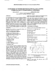
Fig. 1.Configuration used for modelling an actively controlled Constant Power Load based on a Voltage Source Converter
primary control variables of a grid integrated converter, and analyses based on the active and reactive power flow will not directly reveal the properties of the converter currents and voltages. Therefore, a converter-centered analysis will benefit from an analytical approach based on the currents, as in the practical implementation it is the converter currents that are injected to reduce the losses or improve the stability of the system. Due to the restricted over-current capability of a converter, it will also be the total current rating and not the steady-state active and reactive power capability which will impose the limits for safe operation. Based on the above points, this paper presents and follows a current-based approach for analysing the impact of reactive current injection on the losses and stability of the power system under the condition of a constant power flow. The analysis will be general and valid for both loads and generation units with the capability to inject a reactive current component to the grid. It will also be shown how reactive current injection for loss minimization will not necessarily require additional over-rating of the converter. II. ANALYSIS OF A GRID CONNECTED VOLTAGE SOURCE CONVERTER CONTROLLED FOR CONSTANT POWER FLOW A generic three-phase Voltage Source Converter (VSC), connected to a power system modelled by its equivalent Thévenin impedance, will be considered as the simple starting point for the following investigations. A. Investigated Configuration The typical configuration of a grid connected VSC is shown in Fig. 1. The system consists of the converter and its control system, with a constant power load or source on the DC-link, connected to the AC grid through a filter. Considering only fundamental frequency voltages and currents, the configuration in Fig. 1 can be simplified by including the grid side of the filter in the Thevenin equivalent representation of the power system, resulting in the simplified system shown in Fig. 2. In this figure, all variables are expressed in per unit quantities, as commonly applied for power system studies and digital control system implementations. For the following considerations, a vector oriented control system with inner loop current controllers synchronized to the voltage measurements at the grid side of the filter inductor l1 will be assumed [20], [21]. A vector diagram corresponding to rectifier operation of the converter is given in Fig. 3. From this figure, it can be v eq
∼
req
leq
vf i
l1
seen how the synchronous dq reference frame is oriented to the voltage vector vf at the grid side of the filter inductor. From the power system point of view, the converter and its filter inductor l1 can therefore be considered as a controlled current source, as indicated in Fig. 2. However, only the reactive current component, iq, can be controlled freely, while the active current component id must be controlled to maintain the power balance of the system. Assuming a lossless converter and ignoring losses in the filter inductor, the condition of a constant power flow to the DC-link can be expressed on the AC side by (1). (1) p = v f ⋅ id ≈ vdc ⋅ idc = constant B. Mathematical Derivations From the vector diagram of Fig. 3, the voltage balance of the d- and q- axes components can be expressed by (2). v f = veq , d − r ⋅ id + xeq ⋅ iq (2) 0 = veq , q − r ⋅ iq − xeq ⋅ id xeq = ω pu ⋅ leq = leq Assuming the amplitude of the voltage veq to be known, (2) can be rewritten as given by (3). v f = veq ⋅ cos δ − r ⋅ id + xeq ⋅ iq (3) 0 = veq ⋅ sin δ − r ⋅ iq − xeq ⋅ id The sine of the load angle δ can then be expressed in terms of the equivalent grid voltage, the current components and the equivalent system parameters as given by (4). By using trigonometric identities, the cosine of the load angle can be expressed by (5). r ⋅i + x ⋅i (4) sin δ = eq q eq d veq
q
iq i
veq ,q
ϕeq ϕ
δ
v eq req i
id
Current controlled VSC p = constant
jxeq i
veq ,d
∼
vf
Fig. 2.Simplified equivalent circuit of the investigated power system as seen from the current controlled Voltage Source Converter
d
Fig. 3.Vector diagram illustrating the operation of an active rectifier when injecting reactive current to the grid
LS2c.3-2
2
⎛ r ⋅i + x ⋅i ⎞ (5) cos δ = 1 − ⎜ eq q eq d ⎟ ⎜ ⎟ v eq ⎝ ⎠ By introducing (5) into the d-axis voltage balance from (3), the voltage at the terminals of the filter inductor can be expressed by (6).
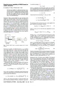
Characteristics of system with 1.0 pu load, x eq = 0.25 pu, req = 0.04 pu
itot ( iq ) = i ( iq ) =
(i (i )) + (i ) 2
d
q
q
2
A. Operation as Constant Power Load The results from numerical analysis of a system with 1.0 pu load are shown in Fig. 4. In this figure, both the active current component and the resulting total current are plotted as a function of the reactive current injected to the grid. The curves are plotted for an equivalent grid voltage veq of 1.0 pu as well as for a voltage of 0.8 pu. To improve the readability of the figure, the sign convention of the reactive current is chosen so that positive values correspond to capacitive operation of the converter. From the figure, it can be clearly seen how the active current component is reduced when the reactive current component is increased. This is because injection of reactive current to the grid is increasing the voltage, and thus, lower active current injection from the converter is needed to transfer the same amount of power. One of the most important results illustrated in Fig. 4 is that the minimum total current does not occur when the reactive current component is zero, corresponding to unity power factor operation, as usually requested for actively controlled rectifiers. Instead, it can be noticed how the total current is reduced when more reactive current is injected, until the total current reaches a minimum. This minimum will correspond to the reactive current injection that will minimize the losses associated with transfer of a specific active power. Another important characteristic illustrated by Fig. 4 is given by the fact that the total current needed to supply a
id(iq) for vg = 0.8 pu itot(iq) for vg = 0.8 pu
i [pu]
1.5 1.4 1.3 1.2 1.1 1 0.9 0.8 0.7
-0.1
0
0.1
0.2
0.3
0.4
0.5 0.6 iq [pu]
0.7
0.8
0.9
1
1.1 1.2
0.2
ploss (iq) for vg = 1.0 pu
0.175
ploss (iq) for vg = 0.8 pu
0.15 0.125 0.1 0.075 0.05 0.025
(8)
III. NUMERICAL ANALYSIS A simple system corresponding to Fig. 2, with xeq = 0.25 pu and req = 0.05 pu, will be analyzed to illustrate the properties of the equations derived in the previous sections. The same system will be analyzed for the case of constant power load as well as for constant generation.
itot(iq) for vg = 1.0 pu
1.8 1.6
ploss [pu]
Although this is an implicit equation without an analytical solution, it can be solved by numerical iteration and analyzed as a function of the reactive current component iq. The total current corresponding to a specific active power p can then be analyzed as a function of the reactive current component according to (8).
id(iq) for vg = 1.0 pu
1.9 1.7
2
⎛ r ⋅i + x ⋅i ⎞ (6) v f = veq 1 − ⎜ eq q eq d ⎟ − req ⋅ id + xeq ⋅ iq ⎜ ⎟ veq ⎝ ⎠ The product of the active current component, id, and the voltage vf must fulfil the condition given by (1). Thus, by imposing the power to be equal to the source or load on the DC-link, the active current component can be expressed as a function of the power and the reactive current component iq, as given by (7). p (7) id = 2 2 veq − ( req ⋅ iq + xeq ⋅ id ) − req ⋅ id + xeq ⋅ iq
2.1 2
-0.1
0
0.1
0.2
0.3
0.4
0.5 0.6 iq [pu]
0.7
0.8
0.9
1
1.1 1.2
Fig. 4.Active current, total current, and losses as a function of the reactive current injection for a 1.0 pu load
1.0 pu load from a voltage of 1.0 pu is always larger than 1.0. Under the assumption of a lossless converter, this is due to the losses in power system, and the constant power characteristics of the load. From the figure, it can also be seen that the system is more sensitive to the reactive current injection when the grid voltage is reduced to 0.8 pu. This tendency is amplified by the constant power load characteristics, where a reduction in the grid voltage will cause an increase in required active current. The increased current will cause additional voltage drop in the line, and thus further contribute to the increase of the active current required at the load terminals. In the case when the grid voltage is reduced to 0.8 pu, the system is also closer to the static power transfer limitation of the line. The theoretical stability limit is also shown in the figure, indicated by a discontinuity of the curves corresponding to the bifurcation point of (7) where no real solution can be found. In the particular case of 1.0 pu load and veq of 0.8 pu, the stability limit is reached with a reactive current injection of about −0.13 pu, corresponding to slightly inductive operation of the converter. This indicates that conventional operation with unity power factor would bring the system quite close to the stability limit, while a passive rectifier with an inductive filter supplying the same constant power could lead to instability. Since the system is pushed closer to the stability limit when the grid voltage is reduced, a higher reactive current injection is required to minimize the total current. Thus, an important result illustrated by the curves in Fig. 4 is that reactive current injection for the purpose of loss minimization will inherently ensure a safe stability margin of the system by keeping the operating point of the load away from the stability limit.
LS2c.3-3
2 1.9 1.8 1.7 1.6 1.5 1.4 1.3 1.2 1.1 1 0.9 0.8 0.7 0.6
2.5
id(iq) for vg = 1.0 itot(iq) for vg = 1.0 id(iq) for vg = 0.8
2
itot(iq) for vg = 0.8
itot [pu]
i [pu]
Characteristics of system with 1.0 pu generation, x eq = 0.25, req = 0.05
1.5
1 0.5 0.4 0.3 -0.1
0
0.1
0.2
0.3
0.4
0.5 0.6 iq [pu]
0.7
0.8
0.9
1
1.1
1.2
0.2
0.2 0.175
0
2
0.5 iq [pu]
Fig. 6. Total current for 1.0 pu load as a function of the reactive current injection and the equivalent grid inductance
0.15 0.125
factor operation. This result is also generally valid, although control systems for generation units are often required to have the possibility for contributing to voltage control or reactive power control and are therefore less dominated by the paradigm of unity power factor control.
0.1 0.075 0.05 0.025 -0.1
0
0.1
0.2
0.3
0.4
0.5 0.6 iq [pu]
0.7
0.8
0.9
1
1.1
1.2
Fig. 5. Active current, total current, and losses as a function of the reactive current injection for 1.0 pu generation
B. Operation as Generator The same system is also investigated for operation as a generator feeding constant power into the grid. The corresponding curves are plotted in Fig. 5, where the same general properties as in the case of a constant power load can be observed. Thus, the losses corresponding to the requested active power transfer can be reduced by injecting a non-zero reactive current to the grid. From Fig. 5, it can be noticed that the minimum total current required to inject 1.0 pu power is below 1.0 pu when the equivalent grid voltage is 1.0 pu. This is because the voltage vf at the converter will increase to a value above the equivalent grid voltage due to the resistive voltage drop in the line It can also be noted that the system is less sensitive to the reactive current injection in this case, compared to the case of a constant power load. This is mainly because the constant power generation has the opposite effect compared to the constant power load, and is therefore contributing to stabilizing the system. Thus, the system has a larger margin with respect to the instability point illustrated for the case of constant power load. In the case when the grid voltage is reduced to 0.8 pu, reactive current consumption corresponding to what made the constant power load to become unstable, will therefore not even bring the system close to instability. Even if all curves plotted in Fig. 5 are less sensitive to the reactive current injection, the point corresponding to the minimum total current can still be easily identified. Similarly to the case of constant power load, this corresponds to loss minimization in the transmission line. Thus, the results in Fig. 5 therefore verify how the reactive current injection from distributed generators can help to minimize the losses compared to unity power
C. Sensitivity Analysis: Influence of Grid Reactance The system described by (7) can also be analyzed with respect to the other variables than the reactive current component. As an example, a three-dimensional plot of the total current as a function of the reactive current as well as of the equivalent grid reactance xeq is shown in Fig. 6. For plotting this figure, a constant power load of 1.0 pu is assumed, and the equivalent grid voltage is assumed to be constant at 0.8 pu The projection of lines representing equal total current into the iq-xeq-plane is also shown in the figure. The specific case of optimal reactive current injection for minimizing the total current is shown as a function of the reactance in Fig. 7. In this figure it is clearly seen how the optimal reactive current is increasing with the total equivalent grid reactance. However, since a higher reactance increases the sensitivity of the grid equivalent with respect to reactive current injection, the corresponding voltage close to the converter will increase so that the necessary active System characteristics with 1.0 pu load and 0.8 pu grid voltage 1.4
1.2
1
0.8 i [pu]
ploss [pu]
0
x eq [pu]
ploss (iq) for vg = 1.0 ploss (iq) for vg = 0.8
1.5
1
0.1
0.6
0.4 Otimal iq(x) Corresponding id(x)
0.2
0 0.05
Minimum itot(x) 0.1
0.15
0.2
0.25 0.3 x eq [pu]
0.35
0.4
0.45
0.5
Fig. 7.Active current and total current corresponding to the point of minimum total current plotted as a function of the grid inductance
LS2c.3-4
Vg
Rg
PCC
Lg
ZT
DC Voltage Controller
PI
vdc ,ref
+
−
k p , DC
Ti , DC ⋅ s
Phase Locked Loop
θ
dq
PI +
k p ,c
−
icd icq
ω pu
Ic
Generation/Load
∼ ∼ ∼
Vc
+
−
=
CDC
sw1,2,3
VDC
I DC
PDC
÷
PWM
+
+
Ti ,c ⋅ s
− d vref
×
l1
k p ,c
v df
1 + Ti ,c ⋅ s
q vref
×
l1 q iref
L1
R1
Current Controllers
d
1 + Ti , DC ⋅ s iref
abc
Vf
1 + Ti ,c ⋅ s
+ q f
v
PI
dq
mβ
αβ
÷
+
+
Ti ,c ⋅ s
mα
÷
θ
Fig. 8.Overview of simulated configuration with converter, control system and grid equivalent
2 1.5
q
i [pu]
A. Simulated Configuration and Control System For the presented simulations, a three-phase converter rated for 2.28 MVA at 690 VRMS line voltage has been assumed, and the converter has been connected to a high voltage grid through a filter inductor and a transformer as indicated in Fig. 8. The series impedance of the grid equivalent and the transformer were selected to achieve leq=0.25 and req=0.05 pu, as used for the theoretical analysis. The load or generation connected to the DC-link was modelled as a controlled current source, with magnitude calculated from a power command and the actual voltage at the DC-link capacitor, as indicated in the figure. For simplicity, and to increase the speed of simulation, the converter has been implemented as an average model neglecting the switching dynamics. The converter model was controlled by a conventional cascaded control system with an outer loop DC-link voltage controller and inner loop current controllers in the synchronously rotating dq reference frame as also shown in the lower part of Fig. 8 [20], [21]. The synchronization of the control system was based on voltage measurements at the grid side of the filter inductor, processed by a traditional synchronous reference frame Phase Locked Loop (PLL) [22]. For all simulations, the DC-link voltage reference has been kept constant at 1.2 pu, while the influence of the q-axis current component has been
B. Verification of Static Profiles and Trajectories To verify the results presented in Fig. 4, simulations representing the two cases of 1.0 pu and 0.8 pu equivalent grid voltage will be presented separately. 1) Simulation with 1.0 pu constant power load and equivalent grid voltage of 1.0 pu Simulated time series resulting from a sweep of the reactive current while operating with a constant power load are shown in Fig. 9. The upper plot in this figure shows the reactive current reference used as input to the control system in Fig. 8, while the second plot shows the resulting d-axis current. It can be clearly seen how the necessary d-axis current is nonlinearly increasing as the capacitive current becomes smaller. The resulting total
1 0.5 0 -0.5 -1
0
1
2
3
4
5
6
7
8
9
10
0
1
2
3
4
5
6
7
8
9
10
0
1
2
3
4 5 Time [s]
6
7
8
9
10
1.5 1.25 id [pu]
IV. VERIFICATION BY TIME-DOMAIN SIMULATIONS To verify the validity of the theoretical analysis, the system from Fig. 1 has been simulated by using the PSCAD/EMTDC software.
investigated by slowly sweeping the q-axis current reference downwards from a capacitive value of 1.5 pu. Only results corresponding to load of 1.0 pu at the DClink will be shown since the case of a constant power load is the most critical with respect to stability, while the general characteristics with respect to current or loss minimization are similar for load and generation.
1 0.75 0.5 -1 2 1.75
itot [pu]
current component required for maintaining the load will decrease. Thus, the total current corresponding to the case of loss minimization is independent of the reactance as shown in Fig. 7 as long, as the resistance is constant. It can be noted that the plot in Fig. 7 indirectly shows the influence of the X/R ratio of the equivalent grid impedance. Since the resistance is specified to be 0.05 pu, the results plotted in the figure correspond to a range of X/R ratios from 1.0 to 10. The influence of the equivalent resistance, the equivalent grid voltage or the load on the optimal reactive current injection can also be easily analysed in a similar way by starting from (7) and (8).
1.5 1.25 1 -1
Fig. 9. Time series of reactive current, active current and total current when iq is swept from 1.5 pu to −1.5 pu while veq =1.0 pu
LS2c.3-5
1,7
Calculated trajectory Simulated trajectory
1.5 iq [pu]
1,6
1 0.5 0 -1
0
1
2
3
4
5
6
7
8
9
10
2 1.75 1.5 1.25 1 0.75 0.5 -1
0
1
2
3
4
5
6
7
8
9
10
0
1
2
3
4 5 Time [s]
6
7
8
9
10
1,4
1,3
id [pu]
itot [pu]
1,5
1,2
1,1
0
0,25
0,5 iq [pu]
0,75
1
1,25
2
1,5
Fig. 10. Comparison of calculated and simulated trajectory of total current as function of reactive current with veq = 1.0 pu
current is plotted in the third plot of the figure, showing a minimum around t = 6 s, when the iq reference is about 0.3 pu. This is corresponding reasonably well to the results from Fig. 4. To further verify the validity of the static curves from Fig. 4, the simulated current trajectory as a function of the iq reference is plotted in Fig. 10 together with the curve resulting from numerically solving equations (7) and (8). From this figure it can be seen that the two curves are corresponding well, although there is a small deviation for low and negative values of iq. This deviation is partly caused by losses included in the simulation model of the converter and the filter inductor, as well as the no-load losses of the transformer, which were not included when deriving equation (7). Additionally, it should be remembered that the simulated trajectory is based on a sweep of reference value for iq, resulting in a quasi-stationary condition slightly influenced by the dynamic response of the current controllers and the DClink voltage controller adjusting the active current reference. 2) Simulation with 1.0 pu constant power load and equivalent grid voltage of 0.8 pu Time series resulting from a simulated sweep of the reactive current reference when the equivalent grid voltage is reduced to 0.8 pu are shown in Fig. 11. For high levels of reactive current injections, the same characteristics as for the case of equivalent grid voltage of 1.0 pu can be observed. However, as predicted by the results in Fig. 4, it can be seen that the system becomes unstable when the reactive current injection is reduced below about −0.1 pu. At this point, the system is approaching the static power transfer limitation of the grid equivalent, and the converter is not capable of supplying the constant load on the DC-link. As the power imbalance starts to deplete the DC-link capacitor the current controllers are saturating while the DC-link voltage collapses, and the converter enters into the state of uncontrollable diode rectifier operation. Thus the total current is increasing quickly, while the active current component is collapsing, since the capability to transfer active power to the DC-link is lost. A comparison of the total current trajectory resulting from the numerical analysis and from the time-domain simulation is shown in Fig. 12. This plot verifies the main characteristics observed from Fig. 4, with the same small
itot [pu]
-0,25
1.75 1.5 1.25 1 -1
Fig. 11. Time series of reactive current, active current and total current when iq is swept from 1.5 pu to −1.5 pu while veq= 0.8 2.1
Calculated trajectory Simulated trajectory
2 1.9 1.8 itot [pu]
1 -0,5
1.7 1.6 1.5 1.4 1.3 1.2 -0.5
-0.25
0
0.25
0.5 iq [pu]
0.75
1
1.25
1.5
Fig. 12. Comparison of calculated and simulated trajectory of total current as a function of reactive current with veq = 0.8
deviation as explained for Fig. 10. It is also verified that loss of stable operation occurs close to the predicted point of instability shown in Fig. 4, although the estimation from the numerical analysis is slightly optimistic due to the neglected losses and dynamics of the system. Thus, the equations presented in section II.B can be used to predict both stability limits and the potential for loss minimization with reasonable accuracy. V. OUTLINE OF POTENTIAL PRACTICAL APPLICATIONS As the time-domain simulations presented in the previous section has verified the general validity and applicability of the theoretical derivations from section II.B, some potential practical applications of the presented approach will be outlined. A. General Mapping of Potential Application Areas The presented results have clearly shown that converter operation with unity power factor will not ensure minimum total current in case of non-zero grid impedance. Thus unity power factor operation will not ensure minimum total losses for a specific load or
LS2c.3-6
B. Searching Algorithms for Loss Minimization In the context of power system operation of converters, local loss minimization by control of the reactive current component has until now been an unexplored area. However, by assuming the characteristics of the total current and losses shown in section II.B, many common features compared to techniques for loss minimization in electric drive systems could be explored. Thus, searching techniques as for instance described in [23]-[25] could be applied for making the converter to track the minimum losses of the system during changing operating conditions with unknown grid parameters, while at the same time ensuring operation with a safe stability margin. Simulation results illustrating a simple example of a searching algorithm for tracking the operating point corresponding to the minimum current and minimum losses are therefore shown in Fig. 13. In this case, the same system as described in section IV.A is simulated with an equivalent grid voltage of 0.8 pu and a load of 1.0 pu. The reactive current injection is stepped up from 0 by steps of 0.25 pu until the interval of the minimum current is identified. Then the interval is halved and the procedure is continued until the minimum is found. The resulting trajectory is shown in Fig. 14, where it can be seen that a minimum current of about 1.375 pu is found for a reactive current injection of about 0.59, corresponding well with the minimum of the simulated quasi-stationary trajectory also shown in the same figure. The simple searching approach shown by Fig. 13 and Fig. 14 is only included for illustrational purposes. For real implementation, a more sophisticated approach should be used, also considering that the reference value for iq should be changed smoothly to reduce the
iq [pu]
0.875 0.75 0.625 0.5 0.375 0.25 0.125 0 -0.125 2.5
2.75
3
3.25
3.5
3.75
4
4.25
4.5
4.75
5
2.75
3
3.25
3.5
3.75
4
4.25
4.5
4.75
5
2.75
3
3.25
3.5
3.75 Time [s]
4
4.25
4.5
4.75
5
1.75 id [pu]
1.5 1.25 1 2.5
itot [pu]
1.75 1.625 1.5 1.375 1.25 2.5
Fig. 13. Time series of currents during search for minimum value 1.8 Simulated quasi-stationary trajectory Simulated searching trajectory 1.7
1.6 itot [pu]
generation, neither for the converter itself nor for the power system. From another point of view, this shows that allowing converters to have the capability for reactive current injection will not necessarily require over-dimensioning by increasing the current rating. The presented equations could therefore be used as a simple screening tool in the process of optimizing the design and operation of converters intended for operation in power systems with non-negligible impedance. For the case of a converter operating with a particular system with a specified load, the presented analysis is also providing the framework for simple loss minimization by calculating the reactive current that will minimize the total current. This can also be used as a starting point for analysing the trade-offs between optimal operation of the converter and the provision of ancillary services like reactive power supply to the grid as discussed in [6]. In this setting, it is important to add that when operating with the minimum total current identified by the presented analysis, the stability of the system is inherently preserved. This can be considered as an added value to the optimization of the network in terms of losses, while providing reactive power as an ancillary service. The general characteristics of reactive current injection illustrated by the presented results can also be used as a starting point for development of on-line optimization algorithms. Such techniques could then be based on current injection from the power electronics units, in contrast to the active and reactive power flow optimization used in classical power systems approaches.
1.5
1.4
1.3 -0.1
0
0.1
0.2
0.3
0.4 iq [pu]
0.5
0.6
0.7
0.8
0.9
Fig. 14. Trajectory of total current during search for minimum value
interaction with the DC-link voltage and the d-axis current controllers. A highly relevant approach would for instance be a hybrid method, where the numerical approach from section II.B is used to find the starting point, followed by a searching algorithms operating with small, filtered, steps, similar to the approach presented for induction machine drive systems in [25]. However detailed algorithm implementation is left as an interesting topic for further research. VI. CONCLUSION A discussion of the properties of optimal reactive current injection for loss minimization by power electronics interfaces in AC systems is presented in this paper. A simple system model is developed to emulate a power electronics interface with a constantly controlled power flow. The mathematical expressions are derived by following a current-based approach that better suits the power electronics interface than the conventional power system approach for loss minimization based on active and reactive power flow. The results of the presented analysis and investigations reveal and highlight the following interesting properties: In general, the minimum system losses do not correspond to unity power factor operation of converter controlled loads and generators. In case of non-zero grid impedance, the minimum total current will therefore not occur when the reactive
LS2c.3-7
current component is zero. Depending on system parameters and power operating point, total current is reduced when nonzero reactive current is injected, until the total current reaches a minimum. The system is more sensitive to the reactive current injection when the grid voltage is reduced, due to operation closer to the static power transfer limitation of the system. The total losses when operating with minimized total current are independent of line inductance, but depend on the resistance or X/R ratio of the line. Reactive current injection by power electronic interfaces will not necessarily require increased current rating of the converter. The properties of reactive current injection for loss minimization are generally the same for generation units and loads, except that for generation units the system is more stable and less sensitive to the reactive current injection The theoretical analysis presented in this paper can be utilized in a wide range of potential applications in the context of power system integration of controlled loads and generators. Provision of reactive power ancillary service for network losses minimization is one clear application area. In addition to form the basis for effective screening tools for loss minimization and stability investigations, the presented approach also opens the topic of searching algorithms for loss minimization applied to grid integrated power electronic converters. This will be especially important in future Smart Grid scenarios where grid integration of converter controlled interfaces based on a “set-and-forget” approach will no longer be acceptable.
[8]
[9]
[10] [11] [12]
[13]
[14]
[15]
[16]
[17]
REFERENCES [1]
[2]
[3]
[4]
[5] [6]
[7]
F. Blaabjerg, Z. Chen, S. B. Kjær, “Power Electronics as Efficient Interface in Dispersed Power Generation Systems,” in IEEE Transactions on Power Electronics, Vol. 19, No. 5, September 2004, pp. 1184-1194 J. M. Carrasco, L. G. Franquelo, J. T. Bialasiewicz, E. Galván, R. C. P. Guisado, M. Á. M. Prats, J. I. León, N. Moreno-Alfonso, “Power-Electronic Systems for the Grid Integration of Renewable Energy Sources: A Survey,” in IEEE Transactions on Industrial Electronics, Vol. 53, No. 4, August 2006, pp. 1002-1016 J. R. Rodríguez, J. W. Dixon, J. R. Espinoza, J. Pontt, P. Lezana, “PWM Regenerative Rectifiers: State of the Art,” in IEEE Transactions on Industrial Electronics, Vol. 52, No. 1, February 2005, pp. 5-22 B. Singh, B. N. Singh, A. Chandra, K. Al-Haddad, A. Pandey, D. P. Kothari, “A Review of Three-Phase Improved Power Quality AC-DC Converters,” in IEEE Transactions on Industrial Electronics, Vol. 51, No. 3, June 2004, pp. 641-660 W. W. Weaver, P. T. Krein, “Mitigation of voltage collapse through active dynamic buffers,” in International Journal of Critical Infrastructures,” Vol. 3, No. 1-2, 2007, pp. 101-123 M. Molinas, D. Moltoni. G. Fascendini, J. A. Suul, R. Faranda, T. Undeland, “Investigation on the Role of Power Electronic Controlled Constant Power Loads for Voltage Support in Distributed AC Systems,” in Proceedings of the 39th IEEE Power Electronics Specialists Conference, PESC 08, Rhodes, Greece, 1519 June 2008, pp. 3597-3602 M. Molinas, J. Kondoh, “Power Electronic Loads as Providers of Reactive Power Ancillary Service to the Grid: Analytical and Experimental study,” in Proceedings of the 13th European Conference on Power Electronics and Applications, EPE’09, Barcelona, Spain, 8-10 September 2009, 10 pp
[18]
[19]
[20] [21]
[22] [23]
[24]
[25]
LS2c.3-8
J. Morren, S. W. H. de Haan, J. A. Ferreira, ”(De-) Stabilising Effect of Power Electronic Interfaced DG Units in Distribution Networks,” in Proceedings of the 11th European Conference on Power Electronics and Applications, EPE 2005, Dresden, Germany, 11-14 September 2005, 10 pp. F. Viawan, A. Sannino, “Voltage Control with Distributed Generation and Its Impact on Losses in LV Distribution Systems,” in Proceedings of the 2005 IEEE Russia PowerTech, St. Petersburg, Russia, 27-30 June 2005, 7 pp. M. H. J. Bollen, A. Sannino, ”Voltage Control With InverterBased Distributed Generation,” in IEEE Transactions on Power Delivery, Vol. 20, No. 1, January 2005, pp. 519-520 M. Belkhayat, “Stability Criteria for AC Power Systems with Regulated Loads,” PhD Thesis, Purdue University, West Lafayette, Indiana, USA, December 1997 L. Harnefors, M. Bongiorno, S. Lundberg, “Input-Admittance Calculation and Shaping for Controlled Voltage–Source Converters,” in IEEE Transactions on Industrial Electronics, Vol. 54, No. 6, December 2007, pp. 3223-3334 D. P. Ariyasinghe, D. M. Vilathgamuwa, “Stability Analysis of Microgrids with Constant Power Loads,” in Proceedings of the 2008 International Conference on Sustainable Energy Technologies, ICSET 2008, Singapore, 24-27 November 2008, pp. 279-284 K.-N. Areerak, S. V. Bozhko, G. M. Asher, D. W. P. Thomas, “DQ-Transformation Approach for Modelling and Stability Analysis of AC-DC Power System with Controlled PWM Rectifier and Constant Power Loads,” in Proceedings of the 13th International Power Electronics and Motion Control Conference, EPE-PEMC 2008, Poznan, Poland, 1-3 September 2008, pp. 20492054 K. Jin, T. H. Ortmeyer, “Application of Static Compensators in Small AC Systems With Constant Power Loads,” in Proceedings of the 2002 IEEE Power Engineering Society Summer Meeting, Chicago, Illinois, USA, 21-25 July, 2002, Vol. 1, pp. 592-596 N. Jelani, M. Molinas, “Loss Minimization in AC Distribution Systems with High Share of Power Electronic Loads Providing Ancillary Reactive Power,” in Proceedings of the 2011 IEEE Trondheim PowerTech, 19-23 June 2011, Trondheim, Norway, 6 pp. M. Céspedes, J. Sun, “Renewable Energy Systems Instability Involving Grid-Parallel Inverters,” in Proceedings of the TwentyFourth Annual IEEE Applied Power Electronics Conference and Exposition, APEC 2009, 15-19 February 2009, Washington, DC, USA, pp. 1971-1977 M. A. Kashem, A. D. T. Le, M. Negnevitsky, G. Ledwich, “Distributed Generation for Minimization of Power Losses in Distribution Systems,” in Proceedings of the 2006 IEEE Power Engineering Society General Meeting, 18-22 June 2006, Montreal, Quebec, Canada, 8 pp. M. Braun, “Reactive Power Supply by Distributed Generators,” in Proceedings of the IEEE Power & Energy Society 2008 General Meeting - Conversion and Delivery of Electrical Energy in the 21st Century,20-24 July 2008, Pittsburgh, Pennsylvania, USA, 8 pp. C. Schauder, H. Mehta, “Vector analysis and control of static VAR compensators,” in IEE Proceedings C, Generation, Transmission and Distribution, Vol. 140, No. 4, pp. 299-306 V. Blasko, V. Kaura, “A New Mathematical Model and Control of a Three-Phase AC-DC Voltage Source Converter,” in IEEE Transactions on Power Electronics, Vol. 12, No. 1, January 1997, pp. 116-123 V. Kaura, V. Blasko, “Operation of a Phase Locked Loop System Under Distorted Utility Conditions,” in IEEE Transactions on Industry Applications, Vol. 33, No. 1, January 2997, pp. 58-63 A. M. Bazzi, P. T. Krein, “Review of Methods for Real-Time Loss Minimization in Induction Machines,” in IEEE Transactions on Industry Applications, Vol. 46, No. 6, November/December 2010, pp. 2319-2328 F. Abrahamsen, “Energy Optimal Control of Induction Motor Drives,”, in M. P. Kazmierkowski, R. Krishnan, F. Blaabjerg, ed. “Control in Power Electronics – Selected Problems,” Elsevier, San Diego, California, 2002, Chapter 6, pp. 209-224 C. Chakraborty, Y. Hori, “Fast Efficiency Optimization Techniques for the Indirect Vector-Controlled Induction Motor Drives,” in IEEE Transactions on Industry Applications, Vol. 39, No. 4, July/August 2003, pp. 1070-1076