Hindawi Mathematical Problems in Engineering Volume 2018, Article ID 2159274, 8 pages https://doi.org/10.1155/2018/2159274
Research Article Study on ADRC Parameter Optimization Using CPSO for Clamping Force Control System Fengping Li ,1,2 Zhengya Zhang,2 Antonios Armaou,3 Yao Xue,2 Sijia Zhou,2 and Yuqing Zhou 2 1
School of Aerospace Engineering, Xiamen University, Xiamen 361005, China Zhejiang Provincial Engineering Lab of Laser and Optoelectronic Intelligent Manufacturing, Wenzhou University, Wenzhou 325035, China 3 Department of Chemical Engineering, Penn State University, State College, PA, USA 2
Correspondence should be addressed to Fengping Li;
[email protected] Received 6 October 2017; Revised 17 February 2018; Accepted 25 March 2018; Published 30 April 2018 Academic Editor: Carlo Cosentino Copyright © 2018 Fengping Li et al. This is an open access article distributed under the Creative Commons Attribution License, which permits unrestricted use, distribution, and reproduction in any medium, provided the original work is properly cited. Clamping force control system is essential for clamping tasks that require high precision. In this paper, Active Disturbance Rejection Controller (ADRC) is applied for clamping force control system, aiming to achieve higher control precision. Furthermore, the CPSO-ADRC system is proposed and implemented by optimizing the critical parameters of ordinary ADRC using chaos particle swarm optimization (CPSO) algorithm. To verify the effectiveness of CPSO-ADRC, Particle Swarm Optimization- (PSO-) ADRC is introduced as a comparison. The simulation results show that the CPSO-ADRC can effectively improve the control quality with faster dynamic response and better command tracking performance compared to ordinary ADRC and PSO-ADRC.
1. Introduction Clamping mechanism has been widely used for workpiece processing in the industrial production [1]. Therefore, clamping force should be accurately regulated to prevent damage to the workpiece. The regulation of clamping force highly relies on the quality of the clamping force controller. Active disturbance rejection controllers (ADRCs) not only inherit the advantages of conventional PID controller, but also make up for the shortcomings, which attracts special attention. Numerous studies have been conducted on the application of ADRC. For example, Tao et al. utilized ADRC to achieve safe and accurate homing of powered parafoils [2]. Zhang and Chen applied ADRC to achieve high precision tracking control of CNC machine tool feed drives [3]. Liu et al. investigated the pitch axis control of satellite camera based on a novel active disturbance rejection controller [4]. Shen et al. tried to solve the control problem of Autonomous Underwater Vehicle (AUV) by designing an active disturbance rejection controller for diving [5].
Though ADRC has many merits compare to conventional PID controller, very limited existence of its application can be found due to its complicated parameter adjustment. To overcome this problem, key parameters of ADRC are usually adjusted in two stages. In the first stage, parameters are roughly adjusted to estimate the ballpark ranges. In the second stage, further optimization to the parameters with specific algorithm is done to determine the precise adjustment. Abundant studies have been conducted for the optimization of ADRC parameters. Observingly, among the optimization algorithms, Genetic Algorithm (GA) [6, 7] and Particle Swarm Optimization (PSO) [8, 9] have been widely used in the optimization process to determine optimal ADRC parameters. Particularly, there are improved variants of GA and PSO algorithms that have even better optimization performance. For instance, the improved GA based on time scale model identification was presented to enable ADRC parameters optimization in a large scope [10]. The adaptive genetic algorithm (AGA) was proposed to solved the adjustment problem towards ADRC systems with overabundant number of parameters [11].
2
Mathematical Problems in Engineering Clamping Mechanism T motor axis
i
Gear Reducer middle rod xa
K J B
xℎ
servo motor
F
ball screw
ball screw axis
clamping block
elastic material
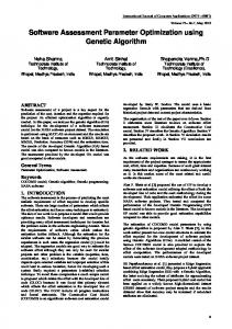
Figure 1: Diagram of clamping mechanism.
i
Control System
Servo Motor
Clamping Mechanism
F
Pressure Sensor
The equivalent torque balance equation for motor axis (see Figure 1) can be described as follows: 𝐽
𝑑𝜃 (𝑡) 𝑑2 𝜃𝑚 (𝑡) +𝐵 𝑚 + 𝑖 ⋅ 𝑇𝐿 (𝑡) + 𝐾 [𝜃𝑚 (𝑡) − 𝜃𝑖 (𝑡)] 2 𝑑𝑡 𝑑𝑡
Improved PSO algorithms also showed superior performances on ADRC parameter optimization. An immune binary-state particle swarm optimization algorithm (IBPSO) was proposed and successfully applied to optimize the parameters of ADRC for chaotic system [12]. A chaos particle swarm optimization (CPSO) algorithm was introduced to conduct optimization and getting optimal parameters for ADRC of an antisynchronizing different chaotic systems [13]. In this paper, ADRC is implemented to clamping force control system with consideration of its superior advantage on robustness. In order to obtain better performance for clamping force control, further parameter optimization of ADRC has been conducted. Instead of ordinary PSO algorithm, CPSO algorithm is applied to this task for its better performance that can converge easier and avoid falling into local optimum. This paper is organized as follows: Section 2 presents the work of establishing mathematical model of clamping force control; Sections 3 and 4 describe the ADRC and CPSO-ADRC design for clamping force control, respectively; Section 5 shows simulation experiments to verify the effectiveness of CPSO-ADRC with PSO-ADRC as comparison and Section 6 proposes some concluding remarks and prospects.
2. System Control Model As shown in Figure 1, the diagram of clamping mechanism is drawn. When the middle rod moves to the left, the two clamping blocks on both sides will move close to each other and thus clamp the workpiece. As shown in Figure 2, 𝜃𝑖 is the servo motor rotation angle and 𝐹 is the clamping force acting on the clamped workpiece. To achieve the clamping force control, the mathematical model of clamping force control system is going to be built in the first step.
(1)
+ 𝑇𝐷 (𝑡) = 0,
Figure 2: Clamping force control system structure.
where 𝐽, 𝐵, 𝐾 are the equivalent total moment of inertia, equivalent total viscous damping coefficient, equivalent total stiffness coefficient, respectively, 𝑖 is the transmission ratio of gear reducer, 𝑇𝐿 (𝑡) is the equivalent load torque, 𝜃𝑖 (𝑡) is the input angle of servo motor, 𝜃𝑚 (𝑡) is the motor shaft equivalent angle, 𝜃𝑚 (𝑡) − 𝜃𝑖 (𝑡) is the shaft relative rotation angle, 𝑇𝐷(𝑡) is the sum of the uncertainty and disturbance torque, and 𝜃𝑚 is related to the middle rod displacement 𝑥𝑎 (𝑡) as 1 2𝜋 𝑥 (𝑡) . 𝑖 𝐿 𝑎 Equivalent load torque can be expressed as 𝜃𝑚 (𝑡) =
𝑇𝐿 (𝑡) = (
𝐿 + Δ𝑘) 𝐹 (𝑡) , 2𝜋𝜇
(2)
(3)
where 𝐹(𝑡) is the clamping force, 𝐿 is the lead-screw pitch, 𝜇 is the reverse stroke efficiency of ball screw, Δ𝑘𝐹 is the uncertain part of equivalent load torque, and Δ𝑘 < 𝐿/4𝜇𝜋. According to the geometric relationship shown in Figure 1, then (4) can be obtained as tan 𝛾 =
𝑥ℎ (𝑡) , 2𝑥𝑎 (𝑡)
(4)
where 𝑥ℎ is the total stroke length of two clamp blocks. Then clamping force is determined as 𝑘𝑥ℎ (𝑡) (5) , 2 where 𝑘 is the stiffness of elastic material. Substituting (2), (3), (4), and (5) in (1) and developing the mathematical expression, the model is now 𝐹 (𝑡) =
𝐽
𝑑𝐹 (𝑡) 𝑖2 𝐿𝑘 tan 𝛾 𝑑2 𝐹 (𝑡) +𝐵 + ⋅ 𝑇𝐿 (𝑡) + 𝐾𝐹 (𝑡) 2 𝑑𝑡 𝑑𝑡 2𝜋 𝑖𝐿𝑘 tan 𝛾 𝑖𝐿𝑘 tan 𝛾 + 𝑇𝐷 (𝑡) = 𝐾𝜃𝑖 (𝑡) . 2𝜋 2𝜋
(6)
Mathematical Problems in Engineering
3 100
Parameters 𝐽 𝐵 𝐾 𝐿 𝑖 𝛾 𝑘 𝜇
Unit kg⋅mm2 N⋅mm⋅s/rad N⋅mm/rad mm / rad N/mm /
Value 1.0 × 10² 10 2.0 × 10⁴ 5 0.32 𝜋/9 10 0.85
Load equivalent torque (N·mm)
Table 1: Clamping force control system’s parameters.
80
60
40
20
0
This model can be expressed as a second-order system, where the state variable 𝑥1 = 𝐹, and 𝑥1̇ = 𝑥2 𝑥2̇ = −𝑎1 𝑥1 − 𝑎2 𝑥2 + 𝑔𝑢 (𝑡) − 𝑑 (𝑡) ,
𝑎2 = 𝑔= 𝑑 (𝑡) =
As 𝐾/𝐽 ≫ (𝑖2 𝐿𝑘 tan 𝛾/2𝜋𝐽)(𝐿/2𝜋𝜇 + Δ𝑘), therefore 𝑎1 = 𝐾/𝐽. The parameters of clamping force control system are displayed in Table 1; then after calculation, we can obtain that 𝑎1 = 200, 𝑎1 = 0.1, 𝑔 = 185.37. And to test the robustness of this system, 𝑑(𝑡) is designed with a Gaussian function (Figure 3): 2
(𝑡 − 𝑎𝑖 ) ), 2𝑏𝑖2
4
5 6 Time (s)
7
8
9
10
Figure 3: 𝑑(𝑡) varying with time.
V2̇ = 𝑓𝑠𝑡 (V1 − V0 , V2 , 𝑟, ℎ) ,
𝑖𝐿𝑘 tan 𝛼 𝑇𝐷 (𝑡) . 𝜋𝐽
𝑑 (𝑡) = 100 exp (−
3
V1̇ = V2
(8)
𝑖𝐿𝑘 tan 𝛼 𝐾 𝜋𝐽
2
Generally, the typical second-order ADRC can be defined as follows. TD is used for arranging the transient process, which can be expressed as
𝐾 𝑖2 𝐿𝑘 tan 𝛾 𝐿 + ( + Δ𝑘) 𝐽 2𝜋𝐽 2𝜋𝜇 𝐵 𝐽
1
(7)
where 𝑎1 =
0
(9)
where 𝑐𝑖 = 5, 𝑏𝑖 = 0.5.
3. ADRC Design ADRC can actively detect disturbance signal from the input and output signals of controlled object and then eliminate the disturbance before it impacts the system by adjusting the control signal. ADRC has three main components [14], tracking differential (TD), extended state observer (ESO), and nonlinear state error feedback (NLSEF). As shown in Figure 4, the ADRC structure for clamping force control system is designed.
(10)
where V0 is the input signal, V1 is the tracking signal of V0 , V2 is the differential signal of V1 , 𝑟 is the parameter which determines the tracking speed, and ℎ is the sampling step length. ESO is the key component of ADRC, which is employed to monitor the output and predict the real-time state of clamping force control system to achieve disturbance compensation; it can be expressed as 𝑒 = 𝑧1 − 𝑦 𝑧1̇ = 𝑧2 − 𝛽01 𝑒 𝑧2̇ = −𝛽02 𝑓𝑎𝑙 (𝑒, 𝛼1 , 𝜂) + 𝑏𝑢
(11)
𝑧3̇ = −ℎ × 𝛽03 𝑓𝑎𝑙 (𝑒, 𝛼2 , 𝜂) , where 𝑦 is the system output, 𝑧1 is the tracking signal of 𝑦, 𝑒 is the deviation signal, 𝑧2 is the differential signal of 𝑧1 , 𝑧3 is the tracking signal of system disturbance, 𝛽01 , 𝛽02 , and 𝛽03 are gain coefficients relating to 𝑒, 𝑢 is the control input, and 𝜂 is the filtering factor. Unlike traditional PID that uses linear strategy, NLSEF is a nonlinear control strategy which can enhance the precision for clamping force control system. It can be expressed as 𝑒1 = V1 − 𝑧1 𝑒2 = V2 − 𝑧2 𝑢0 = 𝛽1 𝑓𝑎𝑙 (𝑒1 , 𝛼01 , 𝜂) + 𝛽2 𝑓𝑎𝑙 (𝑒2 , 𝛼02 , 𝜂) 𝑢 = 𝑢0 −
𝑧3 , 𝑏
(12)
4
Mathematical Problems in Engineering d(t) +
1 v
TD
e1
u0 NLSEF
−
2 +
+ −
e2
b0
1/b0
−
y
Clamping Force Control Model
z3 z2
ESO
z1
Figure 4: ADRC structure for clamping force control system.
Table 2: Common parameters. Parameter Value
ℎ 0.01
𝜂 0.0025
𝑟 100
𝛼01 0.75
where 𝑒1 is the system error, 𝑒2 is the differential of system error, 𝛽1 and 𝛽2 are gain coefficients, and 𝑧3 /𝑏 is the total disturbance compensation of system. The nonlinear function 𝑓𝑠𝑡(𝑥1 , 𝑥2 , 𝑟, ℎ) can be expressed as 𝑢 = 𝑓𝑠𝑡 (𝑥1 , 𝑥2 , 𝑟, ℎ)
𝛼1 0.5
𝛼2 0.25
𝑏 185.37
Table 3: Initial key parameters. Parameter Value
𝛽01 200
𝛽02 700
𝛽03 2000
𝛽1 5.00
𝛽2 0.1
parameters. The common parameters and initial key parameters are determined based on empirical experience, which can be seen in Tables 2 and 3, respectively.
𝑑 = 𝑟ℎ, 𝑑0 = ℎ𝑑
4. CPSO-ADRC Design
𝑦 = 𝑥1 + ℎ𝑥2 𝑎0 = √𝑑2 + 8𝑟 𝑦
(13)
(𝑎0 − 𝑑) { ] × sgn (𝑦) 𝑦 > 𝑑0 {𝑥2 + [ 2 𝑎={ 𝑦 { 𝑦 ≤ 𝑑0 𝑥 + { 2 ℎ 𝑟𝑎 |𝑎| ≤ 𝑑 {− 𝑓𝑠𝑡 = { 𝑑 {−𝑟sgn (𝑎) |𝑎| > 𝑑. The nonlinear function 𝑓𝑎𝑙(𝑒, 𝛼, 𝜂) can be defined as 𝛼 { {|𝑒| sgn (𝑒) |𝑒| > 𝜂 𝑓𝑎𝑙 (𝑒, 𝛼, 𝜂) = { 𝑒 { |𝑒| ≤ 𝜂 1−𝛼 {𝜂
𝛼02 1.5
𝜂 > 0,
CPSO algorithm inherited the advantage of fast convergence from PSO algorithm, and to further avoid falling into local optimum situation, it also adopted CO (Chaos Optimization) algorithm for random traversal. Combining the two gives CPSO great advantage in practice. As shown in Figure 5, flow chart of CPSO algorithm is drawn, where 𝑁 is the number of iterations, pbest is the current optimal solution, and gbest is the global optimal solution. After current optimal solution is obtained by PSO algorithm, further search in the nearby region of current optimal solution by CO algorithm will be continually conducted. The fitness function 𝐽 is designed as follows: ∞
(14)
where 𝛼 is the nonlinear factor. To achieve higher control precision, it is necessary to further optimize the parameters of TD, ESO, and NLSEF. There are two parameters in TD, [ℎ, 𝑟], six in ESO, [𝛼01 , 𝛼02 , 𝛽01 , 𝛽02 , 𝛽03 , 𝑏], and five in NLSEF, [𝛼1 , 𝛼2 , 𝛽1 , 𝛽2 , 𝜂]. In this paper, these parameters are divided into two groups, which are common parameters and key
𝐽 = ∫ (𝜔1 |𝑒 (𝑡)| + 𝜔2 𝑢2 (𝑡)) 𝑑𝑡 + 𝜔3 𝑡𝑢
(15)
𝜔1 + 𝜔2 = 1,
(16)
0
with where 𝑡𝑢 is the rise time, 𝜔1 , 𝜔2 , and 𝜔3 are weighting coefficients. In this work, the weighting coefficients are given as 𝜔1 = 0.99, 𝜔2 = 0.01, and 𝜔3 = 100. The CPSO-ADRC structure for clamping force control system is shown in Figure 6.
Mathematical Problems in Engineering
5 Start
Initialize the particle swarm
Initialize the pbest and gbest
Update particle swarm
Update pbest
Update gbest
Chaos search near the gbest
N= N+1
N < maximum number of
Yes
iterations
No Output gbest
End
Figure 5: CPSO algorithm flow chart. d(t) 1 + v
TD
e1 − e2
2 +
u0 + NLSEF
Clamping Force Control Model
− 1/b0
−
J
y
b0
z3 z2 z1
ESO
Figure 6: CPSO-ADRC structure for clamping force control system.
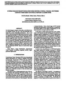
5. Simulation and Comparison Results In order to verify the effectiveness of CPSO-ADRC, PSOADRC is introduced as a comparison, which uses the PSO algorithm to optimize the ordinary ADRC and then simulation experiments are conducted. In Figure 7, the number of iterations is set to 100; it shows that the fitness function 𝐽 of CPSO-ADRC can reach a lower value than that of PSOADRC during the iterative process. As shown in Table 4, the
optimized key parameters have been obtained for both PSOADRC and CPSO-ADRC. In Figure 8, step responses of ordinary ADRC, PSOADRC and CPSO-ADRC are drawn; it reveals that CPSOADRC has higher response speed and stronger robustness compared with ordinary ADRC and PSO-ADRC. To further prove the superiority of CPSO-ADRC, the input signal is changed to square wave, which is rin(𝑘) =
6
Mathematical Problems in Engineering Table 4: Optimized key parameters of ADRC.
Controller PSO-ADRC CPSO-ADRC
𝛽01 230.00 229.96
Parameter 𝛽03 2076.66 2499.26
𝛽02 878.19 792.86
𝛽1 5.90 6.85
𝛽2 0.010 0.013
80
70
60 J 50
40
30
20
0
40
60
80
100
N PSO-ADRC CPSO-ADRC
Figure 7: Comparison between the iterative processes obtained from PSO-ADRC and CPSO-ADRC.
1.2 1
2
Position signal
1 0.8
1 1
0.6
0.96 0.92
0.4
0.88 0
1.01
0.2
0.2
0.4
0.6
0.8
1
2 1
0 0.99
−0.2
4.85
0
1
4.95
2
3
5.05
4
Ordinary ADRC PSO-ADRC CPSO-ADRC
5.15
5 6 Time (s)
5.25
7
8
5.35
9
10
ideal position signal transient position signal
Figure 8: Comparison between step responses obtained from ordinary ADRC, PSO-ADRC, and CPSO-ADRC.
sign(sin(𝑘ℎ)) and the corresponding performances of three kinds of ADRC can be seen in Figures 9 and 10. It can be observed in Figure 9 that the CPSO-ADRC has better performance in responding speed, which is consistent with what Figure 8 implies. And it can also be observed from
Figure 10 that CPSO-ADRC has excellent capability of command tracking. In Figure 11, the control input performances of three controllers are compared. Ordinary ADRC produces significant chattering; PSO-ADRC also generates certain level
Mathematical Problems in Engineering
7
1.5
Position signal
1 0.5 0 −0.5 −1 −1.5
0
1
2
3
4
5 6 Time (s)
7
8
9
10
ideal position signal transient position signal
PSO-ADRC Ordinary ADRC CPSO-ADRC
Figure 9: Comparison between square wave signal responses obtained from ordinary ADRC, PSO-ADRC, and CPSO-ADRC. 0.4 0.3 0.2
Error
0.1 0 −0.1 −0.2 −0.3 −0.4
0
1
2
3
4
5 6 Time (s)
7
8
9
10
Ordinary ADRC PSO-ADRC CPSO-ADRC
Figure 10: Comparison between errors of square wave signal response obtained from ordinary ADRC, PSO-ADRC, and CPSO-ADRC.
of chattering, though much milder than ordinary ADRC; CPSO-ADRC performs the best in reducing chattering; no obvious chattering can be observed from its signal.
6. Conclusion This study focused on improving the performance of active disturbance rejection controllers for clamping force control system via online optimization. The CPSO-ADRC combination was proposed aiming to achieve faster response and better command tracking performance. Simulation studies illustrated that the CPSO-ADRC in this work has exhibited
better dynamic performance. Furthermore, the disturbance signal was designed with a Gaussian function to test the robustness of CPSO-ADRC and the result indicated that CPSO-ADRC has also showed better robustness. To sum all up, CPSO-ADRC has better control performance compared to ordinary ADRC and PSO-ADRC, with similar computational burden to the PSO-ADRC.
Conflicts of Interest The authors declare that there are no conflicts of interest regarding the publication of this paper.
8
Mathematical Problems in Engineering 2 1.5
Control Input
1 0.5 0 −0.5 −1 −1.5
0
1
2
3
4
5 6 Time (s)
7
8
9
10
Ordinary ADRC PSO-ADRC CPSO-ADRC
Figure 11: Comparison between control inputs obtained from ordinary ADRC, PSO-ADRC, and CPSO-ADRC.
Acknowledgments The authors are grateful for the support from the Intergovernmental International Science and Technology Cooperation Foundation of China Key R&D Projects (no. 2016YFE0105900), the Zhejiang Provincial Natural Science Foundation of China (nos. LR13E050002, LQ16105005), and the Wenzhou Technologies R&D Program of China (nos. G20140047, ZG2017003).
Supplementary Materials See supplementary material for the motion simulation video of the studied clamping mechanism. (Supplementary Materials)
References [1] F. P. Li, Z. Y. Zhang, and S. J. Zhou, “Optimized design and kinematic analysis of clamping mechanism for trimming robot,” Chinese Journal of Mechanical Engineering, vol. 27, no. 3, pp. 387–390, 2016. [2] J. Tao, Q. Sun, P. Tan, Z. Chen, and Y. He, “Active disturbance rejection control (ADRC)-based autonomous homing control of powered parafoils,” Nonlinear Dynamics, vol. 86, no. 3, pp. 1461–1476, 2016. [3] C. Zhang and Y. Chen, “High-precision tracking control of machine tool feed drives based on ADRC,” in Proceedings of the ASME 2016 International Mechanical Engineering Congress and Exposition, Phoenix, Arizona, USA, 2016. [4] B. Liu, Y. Jin, C. Zhu, and C. Chen, “Pitching axis control for a satellite camera based on a novel active disturbance rejection controller,” Advances in Mechanical Engineering, vol. 9, no. 2, 2017.
[5] Y. Shen, K. Shao, W. Ren, and Y. Liu, “Diving control of autonomous underwater vehicle based on improved active disturbance rejection control approach,” Neurocomputing, vol. 173, pp. 1377–1385, 2016. [6] H. Geng, H. Yang, Y. Zhang, and H. Chen, “Auto-disturbancesrejection controller design and it’s parameter optimization for aircraft longitudinal attitude,” Journal of System Simulation, vol. 22, no. 1, pp. 89–91, 2010. [7] K. Hu, X.-F. Zhang, and C.-B. Liu, “Unmanned underwater vehicle depth ADRC based on genetic algorithm near surface,” Acta Armamentarii, vol. 34, no. 2, pp. 217–222, 2013. [8] Q.-M. Cheng, Y.-F. Wang, Y.-M. Cheng, K. Wu, and Y.-F. Bai, “Modified double hysteresis current control method for unified power quality controller,” International Transactions on Electrical Energy Systems, vol. 25, no. 4, pp. 713–730, 2015. [9] W. T. Pan, Y. Q. Sun, and J. Sheng, “Simulation of autodisturbance-rejection STATCOM controller based on PSO method,” Computer Simulation, vol. 28, no. 8, pp. 298–301, 2011. [10] H. S. Li and X. F. Zhu, “On parameters tuning and optimization of active disturbance rejection controller,” Control Engineering of China, vol. 11, no. 5, pp. 419–423, 2004. [11] D. Liu, X. L. Liu, and Y. X. Yang, “Research of ADRC and its application based on AGA,” Journal of System Simulation, vol. 18, no. 7, pp. 1909–1911, 2006. [12] Z.-H. Liu, Y.-J. Zhang, J. Zhang, and J.-H. Wu, “Active disturbance rejection control of a chaotic system based on immune binary-state particle swarm optimization algorithm,” Acta Physica Sinica, vol. 60, no. 1, Article ID 019501, 2011. [13] F. C. Liu, Y. F. Jia, and L. N. Ren, “Anti-synchronizing different chaotic systems using active disturbance rejection controller based on the chaos particle swarm optimization algorithm,” Acta Physica Sinica, vol. 62, no. 12, pp. 1–8, 2013. [14] J. Q. Han, “From PID technique to active disturbance rejection control technique,” Control Engineering of China, vol. 9, pp. 13– 18, 2002.
Advances in
Operations Research Hindawi www.hindawi.com
Volume 2018
Advances in
Decision Sciences Hindawi www.hindawi.com
Volume 2018
Journal of
Applied Mathematics Hindawi www.hindawi.com
Volume 2018
The Scientific World Journal Hindawi Publishing Corporation http://www.hindawi.com www.hindawi.com
Volume 2018 2013
Journal of
Probability and Statistics Hindawi www.hindawi.com
Volume 2018
International Journal of Mathematics and Mathematical Sciences
Journal of
Optimization Hindawi www.hindawi.com
Hindawi www.hindawi.com
Volume 2018
Volume 2018
Submit your manuscripts at www.hindawi.com International Journal of
Engineering Mathematics Hindawi www.hindawi.com
International Journal of
Analysis
Journal of
Complex Analysis Hindawi www.hindawi.com
Volume 2018
International Journal of
Stochastic Analysis Hindawi www.hindawi.com
Hindawi www.hindawi.com
Volume 2018
Volume 2018
Advances in
Numerical Analysis Hindawi www.hindawi.com
Volume 2018
Journal of
Hindawi www.hindawi.com
Volume 2018
Journal of
Mathematics Hindawi www.hindawi.com
Mathematical Problems in Engineering
Function Spaces Volume 2018
Hindawi www.hindawi.com
Volume 2018
International Journal of
Differential Equations Hindawi www.hindawi.com
Volume 2018
Abstract and Applied Analysis Hindawi www.hindawi.com
Volume 2018
Discrete Dynamics in Nature and Society Hindawi www.hindawi.com
Volume 2018
Advances in
Mathematical Physics Volume 2018
Hindawi www.hindawi.com
Volume 2018