Proceedings of 2005 Intemational Symposium on Electrical Insulating Materials, June 5-9,2005, Kitakyushu, Japan
P1-59
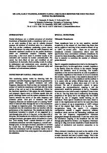
Study on Partial Discharge detection of power transformer based on AVR
Jun Guo *, Wen Shu, Xueqin Zhang, Bo Gao, Peng Wang, and Guangning Wu Southwest Jiaotong University, School of Electrical Engineering, Chengdu, 6 1003l,Sichuan, P.R.China
* E-mail:
[email protected] Abstract: As the increasing voltage grade of power electrical equipment, on-line monitoring and diagnostic of the power transformer’s insulation have become one of the most important studies in high voltage research. At the same time, lots of researches have shown that the insulation aging has direct relationship with the partial discharge (PD) activities. A new instrument, which based on AVR, is introduced to measure the characteristics of PD in large power transformers accurately. In addition, it can also be used to on-line monitoring of the PD activities under high field conditions. Keywords: Partial Discharge, power transformer, on-line monitoring, AVR the transformer’s operation.
INSTRUCTIONS
Most of the current PD on-line monitoring The traditional inspection and repair of
systems are all expensive, with low reliability.
the so-called “maintenance
Using in the traction transformer in the electrical
routine”[]], the preventative maintenance based
railway, these PD monitoring systems are always
on schedule. This kind of maintenance had do lots of contributions to the power equipments’
cost one third or more of the transformer’s price.
overhaul and management. However, this kind
substations. A new PD on-line monitoring
of preventative maintenance can’t monitor the
system, based on AVR micro control unit, has been introduced.
transformer is
transformer’s operation conditions, and it can do nothing with the prediction of transformer’s insulation status and its trend of development. It
That’s too expensive to apply it in all traction
MONITORING PRINCIPLE
indicates that the traditional preventative inspection can not fit the actual requirement. At
The most obvious phenomenon of partial
that time, the real-time, effective insulation on-line monitoring has been widely researched
discharge is the movement of charges between
and
Recently, high voltage power
on the electron of test sample. Moreover, the
equipments’ insulation on-line monitoring and
duration of every discharge is very short, which
dielectrics, which will cause the voltage variety
diagnostics has become one of the important
is about 10 ns in gas or 1 us in oil. Based on
research topics. And the Partial Discharges (PD), as an effective parameter to allude the insulation
Maxwell electromagnetic theory, these fast rise time pulses will generate high frequency
fault and aging, has attracted more and more
electromagnetic signals radiating outside. The
attention. Within the
transformer’s partial
common PD detection methods are all based on
discharge on-line monitoring system, it could not
these two principles. These methods are Pulse
only cooperate with the traditional differential protection, over current protection, heavy gas
Current Detection, Radio Interference Voltage,
protection, etc., but can also real time monitor
The Radio Frequency Monitoring was
Dielectric Loss Analysis, etc.
- 522 -
adopted in this. system, which used a high
sensor. At that time, the sensor’s quantity factor
frequency current sensor, Rogowski coil, to pick
(Q-factor) is above 100. And the sensor’s output
up the discharge signals from the transformer
winding’s neutral ground wire, earth of casing
transfer function is tied up with the Integral Resistor and the tune number of sensor. Ignored
wire and 3-phases entrance bushing. With these
the stray capacitance in the circuit, the output
sensors, it could detect the partial discharges in
transfer function is,
the transformer effectively. in which the R is the resistance of the Integral
SYSTEM CONSTRUCTURE
Resistor, whiie the This PD on-line monitoring system mainly
N is
the tune number of
sensor.
included three parts, the PD sensor, the data collection unit and the workstation, as its show in figure 1.
cormmication
bus
Fig. 2 Rogowski based high frequency current sensor and
Fig.1 Construction block diagram of transformer’s
its equivalent circuit Here, M is the mutual inductance
PD on-line monitoring system
between the winding and the core, .Cs is the stray
PD SENSORS PD sensors are the core of the whole
capacitance of the circuit, Rs is the internal resistance o f
system; it has direct relationship with the design
integral resistance.
the sensor, Ls i s the internal inductance, and R is the
of data collection unit and the measurement effect of the system. Using to detect the wide band, low magnitude, short pulse duration PD
characteristics in the range of 10 lcHz to 20 MHz,
pulses, Rogowski coil based high frequency
it also has other benefits such as fast response,
current sensor was adopted. The sensor’s
high sensitivity, few skewness, safety and
The experiment was shown that this sensor has
flat
amplitude
frequency
response
construction and equivalent scheme are shown in
credibility. Thus, this sensor could not only
figure 2. Here, the Mn-Zn soft magnetic ferrite
collect the PD signals, but also has good
was used for the core of the sensor, which has an
noiseproof feature, which fit for the field PD
excellent response in high frequency (up to 1
detection in substations.
MHz). Also, it decides the sensor’s bandwidth.
DATA COLLECTION UNIT
The bandwidth should be considered seriously. A proper bandwidth wilt get nice results and cut down the cost. In the PD detection, it is quite enough to get an effective result if the discriminable pulses are equal or above 250 per quarter circle[41.In that case, the system was set to work at 100 kHz. So did the
In the transformer’s PD detection, the q-n. ‘p-n figures could be obtained, just from detecting and doing the statistic analysis of PD peak magnitude, peak number and its relationship with phases. With these figures, the transformer’s inside faults could be obtained, the further analysis, such as to assess the operation
- 523 -
status of the'transformer could be done. A 100
frequency, while the bode rate could reach 576
kHz peak-holding data collection system was
kHz Further more, the ATPUS8515 has 64kB
adopted, which fulfilled the demand of the
extended RAM, and its pin form and functions
PD on-line monitoring, and
are similar with the traditional MCU 8051 series,
transformer's
'
decreased the cost of the whole system. The
which have high compatibility with 8051 series
block diagram of this data collection system is shown in figure 3. This system adopted the
point of the PD data collection unit. According
micro control unit (MCU), AT90S8515, as the
to sampling theorem, the sampling rate of data
'core centre process unit (CPU), helping with
collection unit should be 2 times faster than the
peak-holding and sampling circuit, AID converting circuit, and communication level
rate is adopted. Using the traditional data
converting circuit, to collect the PD signals and
coliection unit, the sampling rate should be 600
n
Peak-holding-sampling circuit is the key
signals, actually, 6 or 8 times faster of sampling
kHz in order to detect the 100 lcHz signals,
send these.signals to the workstation.
which is too hard to do for a micro control unit.
Sensor's Output
The peak- holding - sampling circuit was designed to address this problem. Its block diagram is shown in figure 4 I
"
Fig.4 the block diagram of peak-holding circuit
Workstation
The input PD signals firstly compared with
threshold comparator, the comparator opens the
Fig3 The block diagram of data collection unit
The micro control unit, AT9OS8515, is one kind of AVR unit. ARC unit is one kind of Reduced Instruction Set CPU (RISC),designed by Mr. A and Mr. V in 1997. It utilized the
positive peak-holding when the input signal is bigger than the threshold value, while opens the negative peak-holding as the input is lower than the threshold value. The two peak-holdings send
concept of Harvard structure, which could pre-load instructions, so the instructions could be
their output to the switch, which is controlled by
execute per clock period. The AT903 series'
larger one and sends it to the AID converter. The
operation speed can reach 50 ns per instruction consumption is about 1 mA to 205 mA (typical
two peak-holding will be reset every time when the sampling is over. Using this kind of peak-holding-sampling unit, the sampling rate
consumption, 100 nA when WDT dosed). Its
do not be limited by the sampling theorem, 100
inside 16-bits FLASH could re-write more than Receiver (UART) do not tie up with inside timer
lcHz of sampling rate could detect 100 kHz peak values of the PD signal, which is enough for the fault diagnostic and is not hard for the AVR
and SPI,
type's micro control unit.
while working at 20 M H z , and its power
1 000 times. Its universal Asynchronous so it could work at the normal integral
another comparator. The switch chooses the
- 524 -
.
MAX7821, the %-bits high speed AID converter made by MfiZM, was selected to’do
.
CONCLUSION r
..I
* . .
I
the A/D conversion. The sampling time is I O us,
The principle and the construction of the
since the system’s sampling rate is 100 , M z . Th;
,
AID conversion time of MAX7821 ‘is less than 700 ns, so there‘s about 9 us left to do the
’’
peak-holding,
.
AVR based transformer’s PD on-line monitoring
system has been introduced. The system selected
sampling control and other
the wide band current sensor to detect the PD signals so as to assure the anti-jamming,
functions, which is quite enough to assure the
sensitivity and linearity. The high performance
validity of the collection data.
AVR micro contro1.unit was adopted to increase
,
the system’s running speed, and the workstation WORKSTATION
could process the data rapidly and display the results friendly. Different kinds of interface are
Workstation offers an friendly interface and
the further analysis of PD signals. The software is. designed by CVULabwindows, one kind of visual instrument software. Compared with the
set in the system so it could communication with the upper operation system freely.
ACKNOWLEDGEMENT
traditional instrument, the software is the core, .
and it has more flexibility so that the users could
The author acknowledges National Science Fund
add their special functions in it. The main functions are monitoring parameter setting, PD
o f China (NSFC project number 50377035, NSFC project number 5041 1140516), Fok Ying
signal process, fault diagnostic, fault alarm, etc..
Tung Education Fund (project number 91060)
Normally, the system automatic detects the PD two times per day, and calculate the @-q-n 3D
Control and Simulation of Power System and
PD finger print, according to it, the transformer’s
operation status could be estimated. AIL the detecting data are stored in data base in order to reflect the FD development and for reviewing by
and opening project of State Key Laboratory of Generation Equipment of Tsinghua University for their financial support. REFERENCE
the operators and the remote operation system. The software’s structure diagram is shown in figure 5.
+ PD Data Analysis System
[ l ] Xu Qin, Wang Jin. “Summarize of the
research
of power
electrical
instruments’
overhaul,” Electrical Network Technic, Volume 24, Issues, 2000, pp.48-52.
[21 Yan Zhang. “Electrical Insulation on-line Monitoring,” Beijing, Water Conservancy and
Electric Power Press, 1995, Nov. [3] Guo Bihong, Yang Xiaohong. “Analysis of Application
Status
of
Power
Electrical
Instruments on-line monitoring in China,” Electrical Network Technic, 23, Issues, 1999, pp.65-68.
Volume
141 Qiu Changrong. “Electrical Instrument’s Fig. 5 The structure diagram of workstation
Partial Discharge and its Detection,” Beijing, Mechanical Industry Press, 1994, Sep.
- 525 -