AbstractâThis paper studies multi-user multiple-input multiple-output (MU-MIMO) visible light communications (VLC) for indoor broadcast systems. Transmitters ...
IEEE ICC 2015 - Workshop on Visible Light Communications and Networking (VLCN)
Sum-Rate Maximization of Multi-User MIMO Visible Light Communications Thanh V. Pham1 , Hoa Le Minh2 , Zabih Ghassemlooy2 , Takafumi Hayashi3 , and Anh T. Pham1 Computer Communications Lab., University of Aizu, Aizuwakamatsu, Japan Optical Communications Research Group, Northumbria University, Newcastle upon Tyne, UK 3 Foundation of Computer Science Lab., University of Aizu, Aizuwakamatsu, Japan 1
2
Abstract—This paper studies multi-user multiple-input multiple-output (MU-MIMO) visible light communications (VLC) for indoor broadcast systems. Transmitters, configured as multiple LED arrays, and multiple users equipped with multiple photodetectors (PD) are considered. The main challenge in such broadcast systems is the multi-user interference (MUI). In order to completely suppress the MUI, the block diagonalization (BD) precoding technique, originally utilized for radio frequency (RF) communications, will be adopted. Unlike RF counterpart the VLC signal is positive only leading to the modification of the precoding matrix, thus affecting the overall performance. The paper will investigate the lower bound for the sum-rate maximization of all users in the room scale scenario. Furthermore, the findings show that user’s positions and PD’s rotations considerably impact on the VLC system performance Keywords—VLC, multi-user MIMO, precoding, sum-rate maximization.
I.
I NTRODUCTION
In recent years, there has been rapid growth in deployment of light emitting diodes (LED) as an illumination solution for both commercial and home uses. LEDs are gradually replacing the conventional phosphorescent and incandescent lamps due to its benefits of low power consumption, high efficiency and long lifetime. In another aspect, the use of LED for communication purposes, which is known as visible light communication (VLC), has drawn a great deal of attention in research and commercial applications [1], [2]. Taking the advantages of license-free spectrum, high signal-to-noise ratio (SNR) and safety against eavesdropper, VLC is expected to play an important role in the future indoor networking. Deployment of practical VLC systems, however, is facing numerous challenges in which achieving high data rate is one of the major concerns due to the limited modulation bandwidth of the LED. In this regard, multiple separate LED sources are usually utilized to provide higher data rate by means of spatial multiplexing. This typical configuration also helps to meet the minimum brightness requirement (> 300 lux) for lighting a large room/office. As a result, multiple-input multiple-output (MIMO) scheme is a natural progression for indoor VLC systems. Over last few years, we have seen a lot of studies on MIMO-VLC systems including both theoretical analysis and experimental demonstrations [3]–[7]. Nevertheless, those studies mainly considered the systems with only one receiver (unicast transmission). As the nature of VLC is broadcast network, multiple users should be well supported, however this imposes a challenge such as multi-user interference (MUI), as this can result in the performance limitation. In VLC systems, it is generally assumed that there is no coordination between users, it is therefore extremely difficult to deal with MUI at
978-1-4673-6305-1/15/$31.00 ©2015 IEEE
1344
the receiver side. To overcome this, signal processing (i.e. precoding) at the transmitter is a viable solution to cancel the MUI. It should be noted that a number of precoding techniques have been proposed and extensively investigated for radio frequency (RF) broadcast communications. However, different from RF signal which has complex-value, the input signal in optical communications is real and positive (due to LED characteristic). As a result, precoding techniques developed for RF communications cannot be applied directly for VLC systems and adaptation is needed. There have been several studies on multi-user MIMO (MU-MIMO) in the context of VLC systems. A special case of MU-MIMO VLC where users are equipped with only one PD (MU-MISO) have been investigated in [9], [10]. In [10], linear precoders based on minimum mean square error (MMSE) criterion were designed for both cases of perfect and imperfect knowledge of VLC channels. Meanwhile, linear zero-forcing (ZF) and zero-forcing dirty paper coding (ZFDPC) were considered in [9]. The performances in terms of max-min fairness and sum-rate maximization have been derived. For the case of multiple PDs, [11] studied the block diagonalization (BD) precoding technique (a generalization of ZF [12]). It has been found that the BD technique is suitable for VLC communications due to its good performance in the high signal-to-noise ratio (SNR) regime. However, the nonnegativity constraint on input signal has not been taken into account in this study. It is worth noting that this constraint is critical on the design of the precoder (i.e. restricting the degree of freedom of precoder), and thus significantly affecting the performance. In this paper, we therefore study the use of BD precoding for the general MU-MIMO VLC systems with the constraint of non-negativity input signal. In particular, we are interested in the sum-rate maximization problem which is one of the fundamental issue on performance evaluation. As will be shown later, the sum-rate maximization in MU-MIMO VLC systems is a non-convex problem that is very challenging to obtain an exact solution. Thus, a simple lower bound for the sum-rate maximization performance will be presented. In addition, it is found that user’s position and PD’s rotations have a considerable impact on the performance. The rest of the paper is organized as follows. In Section II, the model of MU-MIMO VLC systems with the nonnegativity input signal constraint is introduced. The sum-rate maximization analysis is presented in Section IV. Section IV shows some representative numerical results, and finally we conclude the paper in Section V. Notation: Standard notations are used in this paper. Bold
IEEE ICC 2015 - Workshop on Visible Light Communications and Networking (VLCN)
#"$" ! !" !
!
'" !
#"$% !
#$%&'()!! *+,-)(%&+.!
!% !
Since di is normalized to the range of [−1, 1], the following constraint placing on the precoders wk,i can ensure (4)
3456!2! /01!2!
"!"!"!"!
K "
#"$& !
!& !
"!"!"!"!
3456!7!
!" ! !% ! "!"!"!"! !& !
#() $" ! #() $% !
'() !
i=1
#$%&'()!! *+,-)(%&+.!
upper case letters represent matrices (e.g., A). The transpose of A is written as AT , while |A| denotes the determinant of A. ∥·∥1 is the L1 norm operator and Ik represents an k × k identity matrix. Also, [A]i,j indicates the element at the i−th row and the j−th column and [A]k,: denotes the k−th row. Finally, A ≽ 0 means that A is positive-semidefinite. MU-MIMO VLC M ODEL
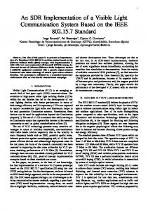
We consider a MU-MIMO VLC system with intensity modulation and direct detection (IM/DD) where NT LED arrays (transmitting units), as transmitters, and K users (K > 1) are deployed (Fig. 1). The i−th user is equipped with NRi PDs. Thus,! the total number of PDs of all users is defined K as NR = i=1 NRi . We assume that NT ≥ NR in order to meet the requirement of the BD precoding technique. Let di ∈ RNRi ×1 be the vector of data symbol intended to the i−th user. Assuming that di is drawn from pulse amplitude modulation (PAM) due to its simplicity and low cost. It is also assumed that di has zero mean and is normalized to the range of [−1, 1]. At the k−th LED array, di is multiplied by a well-designed precoding matrix wk,i ∈ R1×NRi . Therefore, the precoded data signal for the k−th transmitting unit is given by xk =
K "
∀k = 1, 2, ..., NT .
(5)
3456!8!
Figure 1: Schematic diagram of MU-MIMO VLC systems.
II.
bk , m
Without loss of generality, bk and m are chosen to be 1 in this paper. /01!*+ !
#() $& !
∥wk,i ∥1 ≤
wk,i di .
(1)
i=1
However, xk can not be used directly for optical modulation since it may take on negative values. To produce a nonnegative input signal to the LED, a bias bk should be added to xk , i.e., uk = bk + mxk ≥ 0,
(2)
where m is the modulation index (0 < m ≤ 1) which ensures that the LED operates in its linear region and avoids overmodulation induced clipping. The transmitted optical signal then can be expressed by sk = Pt (bk + mxk ),
(3)
where Pt is the average LED power of each array. The inequality in (2) implies a constraint to ensure the non-negativity requirement of the input signal as −bk xk ≥ . m
(4)
1345
A. VLC Channel Considering a single-user MIMO link between LED arrays and the k−th user. In general, there are two main types of link configuration which are direct light-of-sight (LOS) and nondirect line-of-sight (NLOS). However, as pointed out in [1], the LOS link accounts for more than 95% of total received optical power at the receiver. For the sake of simplicity, we thus consider the LOS propagation path only. Denoting Hk ∈ RNRk ×NT is the channel matrix between NT transmitting units and the k − th user ⎡ ⎤ h11 h12 ··· h1NT h22 ··· h2NT ⎥ ⎢ h21 ⎥, Hk = ⎢ (6) . . .. . ⎣ .. ⎦ .. .. . hN R k 1 hN R k 2 · · · hN R k N T
where hij represents the DC gain between the i−th transmitting unit and the j−th PD of the k−th user. For LOS link, hij is given by [1] ⎧ (l+1)A ⎨ 2πd2 cosl (φ)Ts (ψij )g(ψij ) cos(ψij ) , 0 ≤ ψij ≤ Ψc , ij hij = ⎩ 0 , ψij > Ψc , (7) where l is the order of Lambertian emission determined by the semi-angle for half illuminance of the LED Φ1/2 as l = ln(2) ln(cos Φ1/2 ) . A and dij are the active area of the PD and the distance from transmitting unit to PD, respectively. ψij is the angle of incidence, Ts (ψij ) is the gain of optical filter and Ψc denotes the optical field of view (FOV) of the PD. g(ψij ) is the gain of optical concentrator and given by ⎧ 2 ⎨ sinκ2 Ψ , 0 ≤ ψij ≤ Ψc , c g(ψij ) = (8) ⎩ 0 , ψij > Ψc , where κ is the refractive index of concentrator. B. Problem formulation In LOS link, the received optical signal at can be written as ⎡ ⎤ ⎡ s1 1 + x1 ⎢ s2 ⎥ ⎢ 1 + x2 ⎥ ⎢ yk = Hk ⎢ .. ⎣ ... ⎦ = Hk Pt ⎣ . s NT
1 + xN T
the k−th user ⎤
⎥ ⎥. ⎦
(9)
IEEE ICC 2015 - Workshop on Visible Light Communications and Networking (VLCN)
After removing the DC components, the received signal rk ∈ RNRk ×1 is given by ⎡ ⎤ x1 ⎢ x2 ⎥ ⎥ rk = γk mPt Hk ⎢ (10) ⎣ ... ⎦ + zk , xN T
where γk is the responsivity of the k−th PD. zk ∈ RNRk ×1 is the receiver noise vector whose element can be modeled as the sum of ambient-induced shot noise and thermal noise. It is generally accepted that zk is real valued additive white Gaus2 2 sian noise with zero mean and variance σk2 = σshot + σthermal , 2 2 where σshot is the shot noise variance and σthermal is the thermal noise variance [1]. Finally, the noise power is summarized by σk2 = N0 B,
(11)
where N0 is the noise power spectral density and B is the modulation bandwidth. Let’s define Wk = [w1,k , w2,k , ..., wNT ,k ]T ∈ RNT ×NRk as the precoding matrix for the k−th user. As a consequence, the expression in (10) can be rewritten as rk = γk mPt Hk ,
K "
Wi di + zk
i=1
= γk mPt Hk Wk dk + Hk
K "
-
Wi di + zk ,
i=1,i̸=k
(12)
where !KHk Wk dk is the desired received signal whereas Hk i=1,i̸=k Wi di is the MUI term. The constraint in (5) is expressed in term of Wi as K " . . .[Wi ]k,: . ≤ bk , ∀k = 1, 2, ..., NT . 1 m i=1
(13)
In order to completely eliminate the interference term at the received signal, the BD technique imposes a constraint on the precoding matrix Wi as to be orthogonal to the channels associated with all other users. Mathematically speaking, that constraint can be written as follows Hk Wi = 0
for k ̸= i.
(14)
As a result, the lower bound for data rate of the k−th user is given by [8, Eq. (26)] / / / / log 2 T T/ / Rk = log2 /Ik + ∆k Hk Wk Wk Hk /, (15) 2 where ∆k =
(γk m)2 ePt . 2 2πσk
It should be noted that this bound is asymptotically tight at the high SNR regime. Hence, it is reasonable to adopt (15) due to the high SNR usually offered by VLC systems. In MU-MIMO systems, the sum-rate maximization of all users is one of the fundamental problem that is essential for performance evaluation. In the following section, we address this optimization problem under the constraints on precoding matrices described in (13) and (14).
1346
III.
S UM - RATE M AXIMIZATION A NALYSIS
The sum-rate maximization problem under the constraints in (13) and (14) is formulated as / / K " / / log 2 T T/ / maximize log2 /Ik + ∆k Hk Wk Wk Hk / Wk 2 k=1
subject to
Hk Wi = 0, ∀i ̸= k (16) K " . . .[Wi ]k,: . ≤ bk , ∀k = 1, 2, ..., NT . 1 m i=1
In order to solve (16), we remove the first constraint and transform it into an equivalent problem. For each k, defining 0k a matrix H ! 1 T 2 0 k = H ... HT HT ... HT T ∈ R( K i=1,i̸=k NRi )×NT , H 1 k−1 k+1 K (17)
which aggregates all channel matrices except that of the k− user (i.e. Hk ). The zero-interference constraint in (14) requires 0 k . Assuming that H 0k that Wi must lie in the null space of H 0 is a full rank matrix and Lk = rank(Hk ). The singular value 0 k can be obtained as decomposition (SVD) of H 1 2 0 k = U k Σk R k V k T , H (18) where Rk holds the first Lk right singular vectors corresponding to non-zero eigenvalues, and Vk contains the last (NT − Lk ) right singular vectors corresponding to zero ei0 k . Since Vk forms an orthogonal basic for the genvalues of H 0 k , Wk can be any linear combination of Vk , null space of H i.e., Wk = Vk Λk ,
(19)
where Λk ∈ RNRk ×NRk can be any arbitrary matrix subject to the second constraint in (16). Thus, the optimization problem in (16) can be re-formulated as / / K " / / log 2 maximize log2 //Ik + ∆k Hk Vk Λk ΛTk VkT HTk // Λk 2 subject to
k=1 K "
. . .[Vi Λi ]k,: . ≤ bk , ∀k = 1, 2, ..., NT . 1 m i=1
(20)
Since the objective function of (20) is neither convex or concave with respect to Λk , it is generally difficult to have an exact solution. In this paper, we therefore present a simple lower bound solution for (20) by transforming it into a convex optimization problem. Defining Ωk = Vk Λk ΛTk VkT ∈ RNT ×NT . The following inequalities can ensure the constraint in (20) , . 2 !K . .[Vi Λi ]k,: . K i=1 " 1 b2 ≤ [Ωi ]k,k ≤ 2 k . (21) NR m NR i=1 For the proof, refer to the Appendix A. Now, considering the following optimization problem, which gives a lower bound
IEEE ICC 2015 - Workshop on Visible Light Communications and Networking (VLCN)
Table I: MU-MIMO VLC System Parameters Parameter
Table II: User’s positions
Value Room and transmitters configuration
Length (m) × Width (m) × Height (m)
5×5×3
LED array positions
(1.5, 1.5, 3), (1.5, 3.5, 3) (3.5, 1.5, 3), (3.5, 3.5, 3)
LED bandwidth
50 MHz
LED beam angle (LED Lambertian order is 1)
120
User 1
User 2
Scenario 1
(1, 2, 0.5)
(1, 3, 0.5)
1m
Scenario 2
(1, 2, 0.5)
(2, 3, 0.5)
1.414 m
$"
◦
/