simulation for a 2001 Acura 3.2TL. The vehicle rolls several times, resulting in 10
individual impulses at various locations on the vehicle. After executing our ...
SUMMER 2010
ENGINEERING DYNAMICS CORPORATION
Technical Newsletter Available on-line in the EDC Library at www.edccorp.com
Here’s the Latest “Now Available” News! Its been a busy summer here at EDC! Now Available news for member of the
HVE
HVE HVE-2D HVE-CS ,
family,
Heres some
and the newest
I:
2011 HVE Forum The
2011
HVE
Forum
offers
a
wide
selection
of
workshops designed for beginning, intermediate and advanced users of
HVE, HVE-2D & HVE-CSI Version 8.0
HVE, HVE-2D HVE
, and
with Users Groups, the
HVE-CSI
, along
White Paper session and
Version 8.0 is now available! This latest release offers
interactive
users exciting new features, such as the
Workshop schedules, descriptions, registration forms
Model,
along
with
numerous
HVE
Clutch
enhancements to
the
social
hours
at
the
end
of
each
day.
and details about the hotel and discounted room rates
Vehicle, Environment, Event and Playback Editors.
are now available to download from the EDC website.
Click on the
Visit
Version 8 - July 30, 2010 link at the top of the www.edccorp.com for more information.
Program Selection Guide A new Program Selection Guide designed to help you select between
HVE HVE-2D ,
and
HVE-CSI,
and also
the physics programs to use for your reconstructions, is now available. Click on the
Program Selection Guide .
link at the top of the www.edccorp.com
Application System Features
Three tables provide an shown below), a
comparison (as
comparison and also
a comparison of the rich feature set and capabilities of each physics program.
Helpful links take you to more
information about the selected feature or capability.
www.edccorp.com/2011HVEForum or
EDC Customer Service and register today.
contact
Technical Newsletter
SUMMER 2010 collision forces and delta-Vs for vehicles undergoing
Technical Session
multiple impacts, even if the impacts are simultaneous.
DamageStudioÒ
This Technical Session introduces a new tool available in the HVE Playback Editor, called
.
Our technical session is a continuation of the technical session in our previous Newsletter.
DamageStudio
is a graphical analysis tool that allows
the user to visualize collision data, and to correlate collision damage with the kinetics (force magnitude and
A
DamageStudio
window includes a 3-D viewer and
two groups of supporting information:
Ø Ø
Viewer Options Damage Profile
These two new features differentiate
DamageStudio
from
HVEs existing Damage Profile output report window.
direction), delta-V, acceleration and other important collision parameters.
DamageStudio
is an option that
replaces the Damage Profiles output report. A typical HVE
DamageStudio
window is shown in Figure 1.
DamageStudio.
One example is
the ability to directly compare simulated crush dimensions with a measured damage profile. This technique can also be used to fine-tune stiffness coefficients from staged collision data.
DamageStudio
Ø Ø Ø Ø Ø
Geometry, Simulated Damage Geometry, Undamaged Geometry, from File Damage Photograph Damage, User-entered
The current Viewer Option is selected from a dropdown can
also
be
used
to
identify
the
magnitude and direction of individual impulses, peak
Figure 1 - DamageStudio, displaying results for a typical side impact. This example uses 6 crush zones and five crush elevations. Results for elevation number 5 (at the rocker panel) are displayed in the table and viewer. Color-coded crush vectors displayed in the viewer show both the actual crush and free space. The large arrow and sphere are the computed PDOF and impulse center, respectively.
2
The Viewer Options group determines what is displayed in the 3-D viewer. The five options are:
There are many uses for the kind of detailed collision information provided by
Viewer Options
list. Our Technical Session focuses on the
Simulated Damage
option.
Geometry,
SUMMER 2010 When
the
Technical Newsletter
Geometry, Simulated Damage
option
is
selected, the 3-D viewer displays the vehicle damage calculated by the simulation. It is similar to the Damage Profiles output report window currently found in the Playback damage
Editor. profile
As
the
simulation
dynamically
is
updates,
played,
the
showing
the
current damage profile. Unlike the Damage Profiles
DamageStudio
Collision Deformation Classification (CDC) This is a
full
implementation of
SAE
J224B. The
first
two H@
characters are the clock direction of the PDOF; the 3
character is the major contact surface (Front, Right, JD
Back, Left, Top, Undercarriage); the 4 specific
location
of H@
damage
on
the JD
character is the major
surface
defined by the 3
character; the 5
impulse center and color-coded crush vectors showing
damage
(for
free space and actual crush depth.
damage) or damage width along the vehicle-fixed x axis
window,
also
displays
the
PDOF,
elevation
Front,
Right,
character is the Back JD
(for Top and Undercarriage damage); the 6
Damage Profile
is
the
type
of JD
The
Damage
Profile
group
is
enabled
when
the
Geometry, Simulated Damage Damage, User-entered currently
selected
Viewer
Option
is
or
.
For simulated vehicle damage, the Damage Profile
Corner); the 7
damage
(Wide,
Narrow,
and
Left
character
Sideswipe,
character defines the maximum extent
(depth) of crush.
PDOF By definition, the PDOF is the direction of the impulse (and, therefore, the delta-V). Because HVE is
group displays the current impulse number (up to 10
3-dimensional, the PDOF has both an azimuth angle
individual
(the traditional PDOF in the vehicles x-y plane) and a
impulses
per
vehicle
may
be
displayed),
along with the following results for the current impulse:
zenith angle (the vertical component of the PDOF).
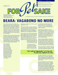
Figure 2 - Playback Editor displaying Damage Data, DamageStudio and Trajectory Simulation windows for our rollover simulation. The current simulation time is 0.540 seconds, the time at which the peak force occurs during Impulse No. 1.
3
Technical Newsletter
SUMMER 2010
Width For side and end damage, this is the horizontal width of damage. For top and undercarriage damage, this is the width of damage in the y-direction.
Offset For side and end damage, this is the horizontal distance from the CG to the center of the damage width.
CollisionData results include:
Kinetics Collision impulse information, including the start, end and time duration of each impulse, as well as the
peak
force,
acceleration,
delta-V
and
PDOF
associated with the impulse.
For top and undercarriage damage, this is the lateral
Damage Profiles
distance from the CG to the center of the damage width.
including the CDC, damage width and width offset, and
Elevation/Distance For side and end damage, this is the
vertical
elevation
at
up
to
five
locations
Damage
profile
information,
damage height and height offset (thats right, were talking 3-dimensional damage profiles!), and maximum crush depth.
(above/below the CG) for the crush depths displayed in
Crush Tables
the crush table. For top and undercarriage damage, this
including elevation and crush depths for five locations.
Detailed
crush
depth
information,
is the x-distance from the CG at up to five locations for the crush depths displayed in the crush table.
Crush Table
These are the actual crush
depth for physically observable damage, the free space and the total crush depth (sum of actual crush depth and free space). Up to 10 crush
depths
may
be
entered
(five
is
the
default).
The 3-D viewer displays the current impulse center and PDOF vector, as well as a set of color-coded arrows (vectors) that illustrate the crush depth and free space for each selected elevation/distance.
Using DamageStudio The following example illustrates the use of
DamageStudio We
have
for analyzing a rollover collision.
set
up
and
executed
a
rollover
simulation for a 2001 Acura 3.2TL. The vehicle rolls several times, resulting in 10 individual impulses at various locations on the vehicle.
After executing our SIMON rollover event, we open
a
Damage
DamageStudio
Data
and
output
report
Trajectory
and
Simulation
windows in the Playback Editor, as shown in Figure
2.
interval
We
to
a
also
set
small
the size,
playback 0.01
output
seconds
(remember, were talking about impulses that last only about 100 milliseconds, or so).
The CollisionData results for this rollover are displayed in SIMONs Damage Data report (see Figure 3). From our previous Newsletter, we learned that CollisionData is a new HVE routine that
calculates
and
provides
a
significant
amount of detailed numeric data describing a collision.
4
Figure 3 - SIMONs Damage Data output report showing CollisionData results for the sample rollover event.
SUMMER 2010
Technical Newsletter
Auto 1
As you would expect, when implemented in SIMON, the
Impulse No. changes from
CollisionData
related damage information for the first impulse are
results
are
fully
3-dimensional,
and
to
, and the CDC and
DamageStudio
include roof and undercarriage damage as well as
displayed in
side/end damage at various elevations.
The current crush vectors and PDOF are displayed in the
Just to focus briefly on one useful application, the CollisionData results can be used to provide detailed
3-D
s Damage Profile group.
viewer. Press
Pause. DamageStudio
Figure 2
Trajectory Simulation and
shows the windows at
precisely this moment.
roof crush measurements for our rollover crash. The
DamageStudio
window for the SIMON simulation is
displayed in Figure 4. The Viewer Option is
Simulated Damage
Geometry,
; the Damage Profile group initially
shows the Impulse No. as
The
Trajectory
context
to
the
Auto
Simulation rollover
Play.
The simulation continues. After the first
impulse is complete, the Impulse No. changes back to
Auto
. When the second impulse begins, the Impulse
.
No.
window
event,
Press
gives
showing
excellent
the
vehicle
changes
to
2
and
the simulation progresses,
results
current
each
DamageStudio
impulse
are
displayed
in
the
window.
damage
information
Figure 5). Allow the simulation to run to completion. As
contacting the ground at the moment the CollisionData for
the
associated with the second impulse is displayed (see
impulse
DamageStudio
information
for
each
displays the successive
impulse.
Now play the simulation. Watch as the first roof collision
Lets say our main interest is the impulse that caused a
occurs. As the vehicle comes down on its roof, the
majority of the roof crush above the drivers head; this is
Figure 4 - DamageStudio showing the crush depths near the top of the A-pillar. This is the area that sustained the maximum roof crush, and also happens to be above the drivers head.
5
Technical Newsletter
SUMMER 2010
the first impulse. We can focus directly on the first impulse by clicking on
DamageStudio
s Impulse No.
dropdown list and choosing Impulse No.
1
. The cur-
What We Learned This example was all about studying occupant injury exposure. The vehicle landed on its roof at t=0.540
rent simulation time moves to the end of the first im-
seconds,
pulse. We can now look at up to 10 crush depths at up
pitch=-13 deg, yaw=-89 deg. The peak acceleration
to five individual locations along the entire length of
was 17.6 g; the PDOF azimuth and zenith angles were
the vehicle. However, we focus on those that involve
-50 and +31 degrees, respectively. The peak roof force
the
Eleva-
was 65,500 lb; the delta-V was 24 mph. The resulting
tion/Distance No. 2. You will see the crush table and
roof crush in the vicinity above the drivers head was 4
roof
above
the
drivers
head.
Choose
the 3-D viewer update accordingly, showing the crush depths
for
the
selected
location.
We
can
then
fine-tune our investigation by directly entering the location at the top of the A-pillar (directly above the
when
its
orientation
was
roll=211
to 6 inches.
Other Viewer Options
DamageStudio Geometry, Simulated Damage The
first
release of
focuses on
viewer
drivers head).
DamageStudio.
deg,
implementation for
HVE
is
complete.
option.
Other
the Its
viewer
We
options are well under way, as is the implementation for
leave it to the creative user to ponder all the other
HVE-2D and EDSMAC4. The obvious difference for
possible uses!
HVE-2D is that damage data and visualization are
This is but one example of using
2-dimensional.
Figure 5 - DamageStudio showing information for the second impulse. This impulse occurred at the right corner of the front bumper. Close inspection of the crush arrows reveals color-coded vectors for free space and actual crush; the measurements are shown in the table.
6
SUMMER 2010
Technical Newsletter
The viewer options under development are:
Geometry, Undamaged
Selecting
HVE and HVE-2D F.A.Q.
this
option
displays the original (undamaged) vehicle geometry for
This
HVE
comparison with the damaged vehicle.
Geometry, From File Selecting this option displays any 3-D model provided by the user. The user would typically select, using a file browser, a CAD model that was created from a scan or total station survey of the actual crash vehicle.
Damage Photograph Selecting this option displays up to seven user-supplied vehicle damage photographs
section
contains
answers
to
frequently
asked
questions submitted to EDC Technical Support staff by and
HVE-2D
users.
Q. My Key Results windows are supposed to be displayed, but they are not visible on my screen. I have unchecked and checked Show Key Results, but they are still not displayed. They were displayed when I was working with a dual monitor configuration with my laptop at my desk, but not now on just my laptop screen alone. How do I get them to display once again?
(six orthographic, one perspective). The user would typically select, using a file browser, one or more photographs that document the damage profile of the actual
A. It sounds like you left the Key Results windows over on the other display, which is pixel real estate that is currently not displayed. One way to fix this condition is
crash vehicle.
to plug back into your dual monitor configuration and
Damage, User-entered Selecting this option displays a
vehicle
damage
dimensions dimensions
shoe-box (an
and
extended
user-entered
version
of
the
move the Key Results windows back to the primary
hve.ini
file on
your computer (its most likely at c:\windows).
The
monitor. The other fix is to search for your
Damage Profiles dialog currently used in the Event
hve.ini file contains information such as the names of
Editor
recently opened case files and also the positions of Key
for
supplying
damage
dimensions
for
an
Results windows on your displays. By deleting this file,
EDCRASH event).
it will reset the initial size and position of your HVE The above views may be superimposed, providing a direct visual comparison between simulated damage and actual damage displayed in a users CAD file or photos, or actual damage dimensions.
Summary CollisionData,
DamageStudio
and Trajectory Simula-
tion results can be used together to provide extremely
program window and also your Key Results windows.
Q. Im working in Version 8, and I just opened an existing case from Version 7.10. Im in Playback looking for the Vehicle Data report, but it is not listed in the available Output Reports. I know it should be there, but its not listed. What do I have to do to get it to appear?
detailed information about a collision. You can correlate collision forces and accelerations directly with crush in-
A.
formation (in our sample case, roof crush) and occu-
report to the list of available outputs simply displaces
pant injury. You can determine the time of peak forces
the Vehicle Data report off the list for an existing case.
and accelerations and correlate those with vehicle ori-
To view the Vehicle Data report, you need to go back
entation and occupant position within a vehicle. In multi-
and reset and reexecute the event. When you return to
ple vehicle collisions (yes, they may be simultaneous),
Playback, you will see that the entire list of reports is
you can identify which collision produced the greatest
available. The results of the event have not changed
force and associated crush.
between 7.10 and 8.00, and the Vehicle Data report will
We are very excited to be introducing
DamageStudio
now be available. in
HVEs next release!
Environment DXF Issues Having
difficultly
environments into
importing
HVE
or
DXF
HVE-2D
models
of
your
? Please contact
EDC Techincal Support for assistance.
your CAD program and for using a convertor program to help you successfully import your DXF model into your and
HVE-2D
Environment Editor.
Q. What is the suggested filename length for cases, textures, vehicle geometry files, etc.? A.
Filenames
(including
must
extension).
be
less Longer
than
30
characters
filenames
are
not
handled properly, which causes unexpected behaviors.
We can offer
helpful tips and suggestions for preparing your file in
HVE
In Version 8, the addition of the new References
Visit the Support section of www.edccorp.com for the latest Downloads and answers to F.A.Q.’s 7
Technical Newsletter
SUMMER 2010 HVE Forum The HVE Forum
EDC Training Courses
HVE, HVE-2D
EDC Reconstruction & EDC Simulations EDC offers excellent one-week courses on the use of
EDCRASH
the
reconstruction program or the use of
simulation programs, such as
EDSVS
and
EDVTS
.
The
EDC Simulations
the
EDSMAC EDSMAC4 ,
,
EDC Reconstruction and
courses are designed to fully
investigate the inner workings of the physics programs .
offers workshops designed to help
HVE-CSI
and
users
modeling and application skills.
improve
their
By participating in
workshops, attendees learn new techniques and also how to use the latest advancements in the software. The
HVE
Forum is also a great opportunity to meet
other users and expand your network of resources.
Lectures are full of helpful hints gained from years of
Course Registration
experience.
To register for a course, download a registration form
physics
During the course, students will use the
programs
to
complete
several
workshops
from the Training page at edccorp.com or contact EDC
highlighting the capabilities of each program discussed
Customer
in the course.
[email protected].
Both new and long-time users of
HVE
and
HVE-2D
agree that these courses are extremely beneficial and challenging. Its the fastest way to learn what you really need to know how to effectively use the physics programs
and
get
the
right
results.
Note:
These
courses focus on the physics programs, not on the user interface.
HVE-CSI
For courses on
, check out the
HVE
using
HVE HVE-2D ,
or
Forum.
the
discussion
scope
by
SIMON HVE for
general several
vehicle direct
providing
such
All
or
by
courses are
email
to
eligible for
HVE Training Partners
HVE HVE-2D ,
and
HVE-CSI
users looking to improve
their skills, but unable to attend one of EDCs regularly scheduled Partner
courses,
for
can
assistance.
HVE
and
contact
HVE HVE-2D
HVE
an
Training
Training
Partners
users
who
are offer
a
solid
simulations.
The
HVE HVE-2D HVE-CSI ,
,
and
compatible
physics
programs.
dynamics
applications
vehicle dynamics simulation program
and
background
a
including
using the within
of
503.644.4500
introductory and custom training courses on the use of
Theoretical & Applied Vehicle Dynamics course
extends
at
Continuing Education Units and ACTAR credits.
experienced
Vehicle Dynamics The
Service
theoretical course
is
focused towards engineers and safety researchers with
HVE Discussion Groups Websites
hosted
by
experienced
information about using
HVE
HVE
Users
offer
as well as moderated
online discussions with other users. Be sure to visit:
an interest in an understanding of vehicle dynamics and automotive chassis systems development.
tech.groups.yahoo.com/group/HVErecon - Discussion group hosted by
Engineering Dynamics Corporation Training Course Schedule
DiscoverHVE.com group hosted by
EDC Simulations Los Angeles, CA . . . . . . . . . January 24 - 28, 2011 Miami, FL . . . . . . . . . . . . . . November 7 - 11, 2011
EDC Reconstruction Los Angeles, CA . . . . . . . . . . January 2012 Miami, FL . . . . . . . .. . . . . November 8-12, 2010
Theoretical & Applied Vehicle Dynamics Upon Request
2011 HVE FORUM Scottsdale, AZ. . . . . . . . . . . February 21 - 25, 2011
8
Roman Beck
of
Casteel, Beck
&
Associates.
-
Online
training
and
discussion
Wes Grimes of Collision Engineering
Associates
Engineering Dynamics Corporation 8625 SW Cascade Blvd, Suite 200 Beaverton, Oregon 97008 USA Phone 503.644.4500 / FAX 503.526.0905 Email:
[email protected] Website: www.edccorp.com
EDCRASH, EDSMAC, EDSMAC4, EDSVS, EDVTS, EDHIS, EDVSM, EDVDS, EDGEN, EDVDB, HVE, HVE-2D, HVE-CSI, HVE Brake Designer and GetSurfaceInfo() are trademarks of Engineering Dynamics Corporation. All Rights Reserved. SIMON, DyMESH (Patent number 6,195,625) and DamageStudio are registered trademarks of Engineering Dynamics Corporation. All Rights Reserved. GATB, GBF, DiscoverHVE.com and PhotoIntoHVE are trademarks of Collision Engineering Associates, Inc.