Superconducting Circuits and Quantum Information∗ J. Q. You and Franco Nori
arXiv:quant-ph/0601121v1 18 Jan 2006
Superconducting circuits can behave like atoms making transitions between two levels. Such circuits can test quantum mechanics at macroscopic scales and be used to conduct atomic-physics experiments on a silicon chip.
Quantum bits, or qubits, form the heart of quantuminformation processing schemes. Because of the quantum parallelism and entanglement that arise from the superposition of states in two-level qubit systems, researchers expect eventual quantum computers to tackle tasks, such as factoring large numbers and simulating large quantum systems, that no ordinary computers can do in a practical time frame. Quantum computing involves preparing, manipulating, and reading out the quantum states of a many-qubit system. So it is desirable to have qubits that can be individually controlled. Moreover, they should be scalable; that is, simply adding more qubits should create a larger circuit capable of more complex calculations. Solid-state qubits satisfy these requirements. Fortunately, very small solid-state devices can behave quantum mechanically. As the size of a bulk conductor becomes increasingly smaller, its quasi-continuous electron conduction band turns into discrete energy levels. An example is a quantum dot, in which electrons are confined to a small semiconducting or metallic box or island composed of millions of atoms. The problem is that the electron states of that island quickly decohere as the microscopic degrees of freedom strongly interact with the environment. A bulk superconductor, in contrast, is composed of many paired electrons that condense into a single-level state. This superconducting state involves macroscopic degrees of freedom and thus exhibits better quantum coherence. By reducing the size of the superconductor, one can reduce the coupling of the superconducting state to the environment and thereby further improve the quantum coherence. Various experiments on superconducting circuits have demonstrated as much [1, 2, 3, 4, 5] and those schemes are regarded as promising candidates of qubits that can process quantum information (see Physics Today, June 2002, page 14). Not surprisingly, there is a deep analogy between natural atoms and the artificial atoms composed of electrons confined in small superconducting islands. Both have discrete energy levels and exhibit coher-
∗ J.Q. You (
[email protected]) is a professor of physics at Fudan University in Shanghai, China. Franco Nori (
[email protected]) is a professor of physics and applied physics at the University of Michigan in Ann Arbor and the director of the Digital Materials Laboratory at Japan’s Institute of Physical and Chemical Research (RIKEN).
ent quantum oscillations between those levels—so-called Rabi oscillations. But whereas natural atoms are driven using visible or microwave photons that excite electrons from one state to another, the artificial atoms in the circuits are driven by currents, voltages, and microwave photons. The resulting electric and magnetic fields control the tunneling of electrons between the superconducting island and nearby electrodes. The effects of those fields on the circuits are the analogues of the Stark and Zeeman effects in atoms.
Box 1. Parameters of Superconducting Qubits Charge Charge-flux Flux Phase EJ /Ec 0.1 1 10 106 10 GHz 20 GHz 10 GHz 10 GHz ν01 1 − 10 µs 1 − 10 µs 1 − 10 µs 1 − 10 µs T1 0.1 − 1 µs 0.1 − 1 µs 1 − 10 µs 0.1 − 1 µs T2 The ratio of two energy sclaes—the Josephson coupling energy EJ and the charging energy Ec — determines whether the phase or the charge dominates the behavior of the qubit. Moreover, a low enough temperature T (kB T smaller than the level splitting of the qubit) prevents the qubit states from thermally smearing. The values listed in the table are approximate orders of magnitude from recent experiments with different cicuits. Here, hν01 is the level splitting of the qubit (that is, the energy-level difference of the two lowest states E1 − E0 ), which depends on the applied bias. T1 is the average time that the system takes for its excited state |1i to decay to the ground state |0i. T2 represents the average time over which the qubit energy-level difference does not vary. The relaxation and decoherence times, T1 and T2 , are strongly affected by the environment of the artificial atom. The readout visibility V , defined as the maximum qubit population difference observed in a Rabi oscillation or Ramsey fringe, can reach more than 96% [1]. The coherence quality factor Q = πT2 ν01 is roughly 105 , the number of one-qubit operations achievable before the system decoheres [2]. Differences between quantum circuits and natural atoms include how strongly each system couples to its environment; the coupling is weak for atoms and strong
2 for circuits, and the energy scales of the two systems differ. In contrast with naturally occuring atoms, artificial atoms can be lithographically designed to have specific characteristics, such as a large dipole moment or particular transition frequencies. That tunability is an important advantage over natural atoms. Josephson junctions—superconducting grains or electrodes separated by an insulating oxide—act like nonlinear inductors in a circuit. The nonlinearity ensures an unequal spacing between energy levels, so that the lowest levels can be addressed using external fields. Two important energy scales determine the quantum mechanical behavior of a Josephson-junction circuit: the Josephson coupling energy EJ and the electrostatic Coulomb energy Ec for a single Cooper pair. EJ = Ic Φ0 /2π, where Ic denotes the critical current of the junction and Φ0 = h/2e is the magnetic-flux quantum. The charging energy Ec = (2e)2 /2C for a Cooper pair, where C is either the capacitance of a Josephson junction or an island, depending on the circuit. In analogy to the usual position-momentum duality in quantum mechanics, the phase φ of the Cooper-pair wave function and the number n of Cooper pairs are conjugate variables and obey the Heisenberg uncertainty relation ∆n ∆φ ≥ 1. Box 1 summarizes the four kinds of superconducting qubits realized in different regimes of EJ /Ec . The charge qubit is in the charge regime Ec ≫ EJ , where the number n of Cooper pairs is well defined and the phase φ fluctuates strongly. The so-called flux and phase qubits are both in the phase regime Ec ≪ EJ , in which the phase φ is well defined and n fluctuates strongly. And the chargeflux qubit lies in the intermediate regime Ec ∼ EJ , in which charge and phase degrees of freedom play equally important roles.
Charge and charge-flux qubits The charge qubit is based on a small superconducting island known as a Cooper-pair box (CPB), which is coupled to the outside world by either one or two weak Josephson junctions and driven by a voltage source through a gate capacitance (see figue 1a). To appreciate how the CPB works, consider a plumbing analogy: The box is like a tank that stores water—or in our case, superconducting electrons in the form of Cooper pairs. Those charges can be pushed in and out of the box using a pump (the voltage source) that moves the charges through a valve (the Josephson junction) and into the superconducting wire that acts as a large reservoir of charges. Often that one junction is replaced by two that are joined to a segment of a superconducting ring and thereby form a symmetric superconducting quantum interference device (SQUID). A magnetic flux Φext that pierces the SQUID controls the rate at which the Cooper pairs flow into and out of the box. When the box’s offset charge, induced by the gate voltage Vg , is about the same as the charge of a single elec-
tron, only two charge states matter: |0i and |1i, which have either zero or one extra Cooper pair in the box. A two-level quantum system thus describes the CPB (see box 2), and the two energy eigenstates |±i are superposition states of |0i and |1i. The charge qubit can be represented using either the charge states {|0i, |1i} or the eigenstates {|+i, |−i}. When the gate-voltageinduced offset charge ng (in units of 2e) increases from 0, the ground state of the system continuously changes from |0i to |−i. Similarly, the higher energy level |1i becomes |+i for increasing ng . At the degeneracy point ng = 0.5, where the √ energy levels for |0i and |1i cross, |±i = (|0i ∓ |1i)/ 2.
Box 2. Cooper-Pair Box For the Cooper-pair box (CPB) shown schematically in figure 1a, the Hamiltonian of the system is H = Ec (n − ng )2 − EJ cos φ ,
(1)
where Ec and EJ are the charging and Josephson energies, respectively. The phase drop φ across the Josephson junction is conjugate to the number n of extra Cooper pairs in the box. In the charging regime Ec ≫ EJ , only the two lowest-lying charge states of the box, differing by one Cooper pair, are important. The gate voltage Vg controls the induced offset charge on the box; ng = Cg Vg /2e, where 2e is the charge of each Cooper pair and Cg the gate capacitance. Around ng = 1/2, the system can be described like any two-level atomic-physics-like system with the reduced Hamiltonian 1 H = ε(ng ) σz − EJ σx , 2
(2)
where ε(ng ) = Ec (ng − 1/2). The Pauli matrices σz = |0ih0| − |1ih1| and σx = |0ih1| + |1ih0| are defined in terms of the two basis states corresponding to zero and one extra Cooper pair in the box. With a two-junction superconducting quantum interference device, EJ becomes a very useful, tunable effective coupling: EJ (Φext ) = 2EJ0 cos(πΦext /Φ0 ), where EJ0 is the Josephson coupling energy for each junction, Φext is the external magnetic flux, and Φ0 the flux quantum. Figure 2 shows the energy spectrum of the CPB for two values of the ratio Ec /EJ . The regime near Ec /EJ = 5 is typical of many charge qubits studied in the literature. Indeed, quantum coherent oscillations in circuits were first demonstrated in this regime [1] and experimental results showed that the qubit can be well approximated by a two-level system. When Ec /EJ = 1, both charge and flux degrees of freedom play equally important roles. As shown in figure 2b, the two lowest levels are not well separated from the higher levels. Because the qubit now operates in the
3
ng = 0.5
(a) Cooper-pair box Cg Vg
n -2e
Energy
CHARGE
EJ
EJ |0〉 |1〉
box
n
Charge
φext = π
(b) Magnetic-flux box (rf-SQUID) M Energy
L PHASE
EJ
φ
∆
Iext
Φ0
Phase
φ2 Phase
φ1 φ 2 Iext
αEJ
Phase
Iext
Energy
EJ
φ
φ1
Iext ~ Ic
(d) Current-biased junction
PHASE
φ φext = π
(c) 3-junction magnetic-flux box EJ EJ M
PHASE
|1〉 |0〉
readout
|2〉 |1〉 |0〉
Phase
φ
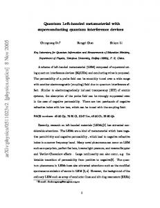
FIG. 1: Superconducting qubit circuits and their potential energy diagrams. (a) A Cooper-pair box (CPB; blue) is driven by an applied voltage Vg (green) through the gate capacitance Cg to induce an offset charge 2e ng = Cg Vg . A Josephson junction, the barrier denoted by the ×, connects the box to a wire lead. Each junction has a capacitance and a Josephson coupling energy EJ . The electrostatic energy of the CPB, Ec (n − ng )2 , where Ec = (2e)2 /2C, is plotted as a function of the number n of excess electron pairs. The lowest energy states, |0i and |1i (in red), are degenerate at ng = 0.5, and are used as the qubit state basis. Those states are coupled via the junction energy EJ , which controls the tunneling between them. (b) A magnetic-flux “box” (blue) is the magnetic analogue of the electrostatic CPB. A magnetic bias simply replaces the electric bias: A current-driven magnetic field pierces the box with a strength given by a mutual inductance M . Whereas an electric field prompts stored electron pairs to tunnel into or out of the CPB, a magnetic field pushes magnetic flux quanta Φ0 into or out of the superconducting quantum interference device (SQUID) loop. The adjacent potential energy diagram plots a Josephson energy term (proportional to cos φ) and an inductive energy term—proportiona to (φ − φext )2 /2L, where L is the SQUID’s inductance—as a function of the phase φ of the junction. The lowest energy states (red) are superpositions of the clockwise and counterclockwise supercurrent states | ↓i and | ↑i that flow in the SQUID loop; ∆ here is the tunneling energy between the supercurrent states. Those energy states are degenerate when the externally applied magnetic flux φext equals π. (c) A three-junction flux qubit works like a magnetic flux box, except that one of the junctions has a slightly different capacitance and coupling energy. The contour plot shows the potential energy as a function of two junctions’ phases. The two red dots inside the potential wells correspond to the qubit basis states | ↓i and | ↑i. (d) A current source biases the junction in a phase qubit. Logic operations can be achieved by driving the qubit with a microwave field at frequency (E1 − E0 )/h. Pulsing the qubit with a microwave field at a frequency (E2 − E1 )/h produces a transition from |1i to |2i. One can then read the qubit’s state by measuring the occupation probability of state |2i.
4 (a)
Charge Qubit E c = 5EJ
(b)
(a) Flux Qubit
Charge-Flux Qubit E c = EJ
(b)
EJ = 9Ec
E/EJ
E/EJ
2.0
1
1.6
0 -0.5
0.0
0.5
ng
1.0
1.5 -0.5
0.0
0.5
1.0
1.5
ng
FIG. 2: Energy levels of a Cooper-pair box versus the offset charge ng (in units of 2e, twice the charge of an electron) that is induced by the gate voltage. (a) When Ec /EJ = 5, typical conditions for the charge qubit, the two lowest energy levels start to approach each other as the offset charge on the box increases from 0 to 0.5. As ng slowly increases in that range, eigenstates of the two levels change from charge states |0i and |1i to |±i, superpositions of |0i and |1i. They become pure charge states again at ng = 1. When ng is about 0.5, the two lowest energy levels are well separated from the other levels. (b) In the case where Ec /EJ = 1, the charge and flux degrees of freedom play equally important roles.
intermediate regime between charge and flux, it is often specified as the charge-flux qubit. In contrast with the eigenstates of the ideal charge qubit, the charge-flux qubit’s two lowest eigenstates |±i are superpositions of several charge states, instead of just |0i and |1i. Thus only {|+i, |−i} can be used as the basis states for the charge-flux qubit. This qubit can exhibit coherent oscillations with a long decoherence time [2]—on the order of 0.5 µs.
Flux qubit The phase degree of freedom becomes dominant in the so-called flux qubit. As sketched in figure 1c, the prototypical flux qubit consists of a superconducting loop with three junctions, and the Josephson coupling energy is much larger than the charging energy for each junction. When a magnetic field is applied through the loop, a clockwise or counterclockwise supercurrent is induced to decrease or increase the enclosed flux such that the fluxoid, which combines the Josephson phase φ with the total magnetic flux (both external Φext and induced Φind ), is quantized: (Φ0 /2π) φ + Φext + Φind = m Φ0 , where m is an integer. The two circulating supercurrent states can form the basis states for the qubit. Five years ago, a one-junction flux qubit of the type sketched in figure 1b was fabricated and its spectroscopic features were demontrated [3]. Flux qubits can come in one- or many-junction flavors; the one-junction case requires a relatively large loop inductance, which makes the qubit more susceptible to magnetic-field noise. For a description of the energy spectrum that arises in
0.46
0.50
f
0.54
0.49
0.50
0.51
f
FIG. 3: Energy levels of a three-junction flux qubit versus reduced magnetic flux f = Φext /Φ0 . Φext is the external magnetic flux and Φ0 the flux quantum, h/2e. (a) The energy-level diagram shows only six levels, the two lowest of which are used for the qubit. (b) An enlarged view of those levels near f = 1/2 (green rectangle) illustrates what happens as the reduced magnetic flux varies around that value. Away from f = 1/2, the two eigenstates approach the clockwiseand counterclockwise-circulating supercurrent states |↓i and |↑i; at f = 1/2, they are maximal superpositions of the two circulating supercurrent states. The potential energy minimum shifts from the right-hand side of the double well for f < 0.5 to the left-hand side for f > 0.5, where |↑i becomes the minimum-energy state.
a multi-junction flux-qubit system, see figure 3 (figure 1c pictures the corresponding circuit). In the vicinity of f = Φext /Φ0 = 0.5, |−i and |+i, the two lowest levels (the qubit levels), are well separated from other higher levels, and are superpositions of the clockwise and counterclockwise supercurrent states |↓i and |↑i. For f < 0.5, |−i and |+i approach |↓i and |↑i; for f > 0.5, |−i and |+i approach | ↑i and | ↓i.√At f = 0.5, the states √ are given by |−i = (|↑i + |↓i)/ 2 and |+i = (|↑i − |↓i)/ 2. As in the case of the charge qubit, one can use either {|↑i, |↓i} or {|−i, |+i} to equivalently represent the flux qubit. For the past five years researchers have studied the three-junction flux qubit, and in 2003 first observed its quantum coherent oscillations [4].
Phase qubit The so-called phase qubit usually uses a large currentbiased Josephson junction, as pictured in figure 1d. The bias current produces a tilt to the Josephson potential; the Josephson potential itself is proportional cos φ. That tilt reduces the number of bound states in the potentialenergy well. The ratio EJ /Ec is orders of magnitude higher in the phase qubit than in other qubit types. The circuit’s potential energy diagram illustrates a third energy level not widely separated from the two lowest levels used for the qubit. The small energy spacing means that appreciable qubit-state leakage to that third level can occur. However, the problem can at least partly turn into an advantage when it comes to measuring the
5
(a)
(b) Cm
C1
C2
L C1
C2
V1
(c)
V2
Φext
V1
(1) Φext
(2) Φext
V2
(d) I1
Cm
I2
L
the Josephson coupling energies in the flux qubits are stronger than those in the charge qubits, the circulating supercurrents in the qubit loops are larger. Therefore, a much smaller inductance produces a relatively strong interbit coupling [9]. Recently, coupling flux qubits with mutual inductances was experimentally realized [10]. Two phase qubits can be similarly coupled using a mutual capacitance, an experimental achievement made by researchers [11]. Again, the lowest two levels for each phase qubit are not widely separated from the third one. That means that energy levels beyond the qubit are also involved in the coupling and relatively serious qubit-state leakage can occur for the two-qubit gate. Achieving controllable interbit coupling is still a challenge in general for any type of qubit.
Box 3. Controlled-NOT Gate FIG. 4: Coupling qubits. (a) Two charge qubits (blue) coupled by a mutual capacitance Cm between the two boxes. (b) Two charge qubits coupled by a shared inductance L; each box (blue) is connected to two Josephson junctions instead of one. (c) Two three-junction flux qubits coupled by the common inductance L. (d) Two phase qubits coupled by the mutual capacitance Cm between them.
phase qubit’s actual quantum states. The state of the third level can easily tunnel out of the potential well and thus be used for determining the occupation probability of the qubit levels. Alternatively, one can read out the qubit state by tilting the potential to allow tunneling directly from |1i. Independent research groups have experimentally demonstrated the quantum coherent oscillations in phase-qubit circuits [5]. A phase qubit can also be configured into a circuit similar to what’s shown for the magnetic-flux box in figure 1b by biasing the junction using a flux threading the loop instead of using a current. Such a flux-biased phase qubit works with levels in a tilted well, as depicted in figure 1d.
Coupling qubits Two-qubit operations are required for quantum computing. A natural way to couple circuit-based qubits to build logic gates is to use capacitors and inductors. Figure 4 illustrate a few circuit configurations that could do the job. Recent experiments have shown quantum coherent oscillations in two capacitively coupled charge qubits and demonstrated a working controlled-NOT (CNOT) gate [6]. However, controlling the interbit capacitive coupling is a difficult problem [7]. An alternative is to couple charge qubits via an inductance [8], which produces a flux-controllable interbit coupling and can be conveniently used to achieve a CNOT gate (see box 3). An inductance can also couple flux qubits. Because
For the two inductively coupled qubits shown in figure 4b, when the gate voltage is shifted to the degeneracy point ngi = 1/2 (i = 1, 2) for each qubit, the Hamiltonian of the system becomes ∗ ∗ H = −EJ1 σx(1) − EJ2 σx(2) + χ σx(1) σx(2) , ∗ where EJi slightly deviates from EJi and the interbit (i) coupling χ is controllable via the external fluxes Φext . This 4 × 4 Hamiltonian has four eigenvalues with corresponding eigenstates |+, +i,|+, −i,|−, +i, and |−, −i, √ where |±i = (|0i ∓ |1i)/ 2. The Hamiltonian also has the interesting property that its eigenvalues change with the interbit coupling, but the corresponding eigenstates remain unchanged. Because the energy levels of those four eiegenstates are not equally spaced, a microwave field applied to the coupled qubits through either gate capacitance can be tuned to make transitions only between states |−, +i and |−, −i. When a π pulse from such a field is applied, those states flip to produce a CNOT gate: |+, +i −→ |+, +i, |+, −i −→ |+, −i, |−, +i −→ |−, −i, and |−, −i −→ |−, +i. That is, the state of the second qubit is flipped if the first qubit state is |−i, and the second qubit is not affected if the first qubit state is |+i. (See reference [8].)
Cavity quantum electrodynamics A quantized electromagnetic field can coherently exchange energy with a two-level system, usually in a tiny laser cavity. This energy exchange between the field and the system, called Rabi oscillations, occurs at a rate ν proportional to the strength of the system-field coupling. Among such coherent processes, the most elementary one involves the interaction of a two-level system with a single photon. The exchange of energy between the system and the photon is observable in the “strong coupling” regime, when the period 1/ν of the Rabi oscillations is much shorter than both the decoherence time of the two-
6 level system and the average lifetime of the photon in the cavity. The strong-coupling limit has been achieved for a variety of atoms interacting with the light field in a cavity and forms the basis of a subject called cavity quantum electrodynamics (QED). In principle, any type of two-level quantum system can substitute for the atom, and the charge qubit, as a macroscopic quantum system, is a natural candidate. Indeed, we and the Yale group proposed schemes to process quantum information by coupling a charge qubit with a quantized microwave field. One approach took advantage of magnetic coupling through a SQUID loop [12] and the other exploited the control given by the gate voltage and capacitive coupling [13]. In a more recent experiment, Ref. 14 carried out those proposals by using a gate capacitor to couple the photon to a Cooper-pair box, an accomplishment coined “circuit QED” because it translated the cavity QED concept onto a solid-state chip (see Physics Today, November 2004, page 25). The researchers reached the strong-coupling regime using a quasi-one-dimensional transmission-line resonator. In contrast to cavity QED, where atoms move around and only briefly interact with the field, circuit QED uses a charge qubit that is fixed on the chip. More important, the dipole moment that couples the two-level system with the quantized field can be as much as 105 times larger for superconducting charge qubits than for alkali atoms. The experiment can take different forms. Other roups have modified it by replacing the cavity with a hamonic oscillator formed by a Josephson junction (or SQUID) and a nanomechanical resonator [15]. Future ways to exploit superconducting qubits include, for example, preparing Schr¨odinger cat states of the cavity field by means of its coupling to a SQUID-based charge qubit, and the exciting possibility of generating nonclassical photon states using a superconducting qubit in a microcavity [16]. Clearly, the experiments are opening new research directions.
Noise and decoherence Although superconducting circuits exhibit good quantum coherence, they still experience significant levels of noise due to their coupling to the environment. For charge qubits, the dominant source of decoherence is 1/f noise, which is presumably due to background charge fluctuations—trapped charges in the substrate and oxide layers of the Josephson junctions, for instance. For flux and phase qubits, 1/f noise again seems to be dominant, but its origins are less clear. When the CPB operates in the charge-flux regime, the decoherence of the qubit is significantly reduced [2]. Moreover, the decoherence can be suppressed at the degeneracy point by tuning the magnetic and electric fields [2] so that the influence of both flux and charge noise sources vanishes to first order. To try to understand the decoherence problem, re-
searchers have used phenomenological theories including the spin-boson [17] and spin-fluctuator [18] models in which a collection of spectrally distributed harmonic oscillators and a set of particles that fluctuate randomly in a double-well potential, respectively, describe the noise. Such models capture some typical features of decoherence in superconducting qubits. Nevertheless, understanding the microscopic mechanisms of 1/f noise requires further work—for instance, developing microscopic theories beyond phenomenological models. Such understanding is important not only for quantum computing, but also for revealing the underlying physics. The problem has proven to be quite difficult, however.
What lies beyond Decoherence is a major obstacle to superconducting quantum computing; the efficient and nondissipative readout of qubit states, however, is also crucial and will play a central role in future developments. Thus, it is still too early to say which type of qubit might win the race of quantum computing. While unveiling the microscopic mechanism of 1/f noise, one could develop novel methods to actively suppress the effects of the noise. Also, to increase both decoherence time and readout efficiency of the system, one can optimize the qubits by varying the circuit parameters and could couple two or three qubits with optimal designs; a three-qubit circuit could be used to test some simple quantum algorithms, such as the Deutsch algorithm, one of the simplest that illustrates the nature of quantum parallelism. So far, all quantum states on the so-called Bloch sphere—a geometrical representation of the states of a two-level system— can be addressed; spin-echo techniques, borrowed from nuclear magnetic resonance, can reduce the effect of 1/f noise; and readout efficiency greater than 96% and a coherence quality factor of approximately 105 can be achieved, albeit not in the same circuit. When techniques for manipulating two or three qubits become well established, the next step will be to build circuits with a larger number of qubits, increased readout efficiency, and lower decoherence. Such conditions would allow quantum computing with superconducting qubits. But even if no quantum computing is ever achieved with superconducting circuits, they still provide researchers with tools to test fundamental quantum mechanics in novel ways. For example, these artificial atoms can be used to simulate atomic physics using quantum circuits; researchers have already observed Rabi oscillations and Ramsey interference patterns that are manifest during the phase evolution of a superconducting qubit. Moreover, the device can also test Bell inequalities, produce Schr¨odinger-cat states, and simulate the EinsteinPodolsky-Rosen experiment. The quantum engineering of macroscopic entangled states will surely play a central role in several future technologies.
7 We thank our collaborators and other colleagues, many listed below, for their valuable contributions. This work was supported in part by the National Security Agency, Advanced Research and Development Activity, Air Force Office of Scientific Research,, NSF, and NSFC (National Natural Science Foundation of China).
[1] Y. Nakamura, Yu.A. Pashkin, and J.S. Tsai, Nature 398, 786 (1999); T. Duty et al., Phys. Rev. B 69, 140503(R) (2004); O. Astafiev et al., Phys. Rev. B 69, 180507(R) (2004); A. Wallraff et al., Phys. Rev. Lett. 95, 060501 (2005). [2] D. Vion et al., Science 296, 886 (2002); A. Cottet et al., Physica C 367, 197 (2002); E. Collin et al., Phys. Rev. Lett. 93, 157005 (2004). [3] J.R. Friedman et al., Nature 406, 43 (2000). [4] C.H. van der Wal et al., Science 290, 773 (2000); T.P. Orlando et al., Phys. Rev. B 60, 15398 (1999); I. Chiorescu et al., Science 299, 1869 (2003); S. Saito et al., Phys. Rev. Lett. 93, 037001 (2004); B.L.T. Plourde et al., Phys. Rev. B 72, 060506 (2005). [5] Y. Yu et al., Science 296, 889 (2002); J.M. Martinis et al., Phys. Rev. Lett. 89, 117901 (2002); R.W. Simmonds et al., Phys. Rev. Lett. 93, 077003 (2004). [6] Yu.A. Pashkin et al., Nature 421, 823 (2003); T. Ya-
mamoto et al., Nature 425, 941 (2003). [7] D.V. Averin and C. Bruder, Phys. Rev. Lett. 91, 057003 (2003). [8] J.Q. You, J.S. Tsai, and F. Nori, Phys. Rev. Lett. 89, 197902 (2002). [9] J.Q. You, Y. Nakamura, and F. Nori, Phys. Rev. B 71, 024532 (2005); B.L.T. Plourde et al., Phys. Rev. B 70, 140501(R) (2004). [10] A. Izmalkov et al., Phys. Rev. Lett. 93, 037003 (2004); J.B. Majer et al., Phys. Rev. Lett 94, 090501 (2005). [11] A.J. Berkley et al., Science 300, 1548 (2003); P.R. Johnson et al., Phys. Rev. B 67, 020509(R) (2003); R. McDermott et al. Science 307, 1299 (2005). [12] J.Q. You and F. Nori, Phys. Rev. B 68, 064509 (2003). [13] A. Blais et al., Phys. Rev. A 69, 062320 (2004); J.Q. You, J.S. Tsai, and F. Nori, Phys. Rev. B 68, 024510 (2003). [14] A. Wallraff et al., Nature 431, 162 (2004). [15] I. Chiorescu et al., Nature 431, 159 (2004); M.D. LaHaye et al., Science 304, 74 (2004). [16] Y.X. Liu et al., Europhys. Lett. 67, 941 (2004). [17] Yu. Makhlin, G. Sch¨ on, and A. Shnirman, Rev. Mod. Phys. 73, 357 (2001); A. Shnirman, Yu. Makhlin, and G. Sch¨ on, Phys. Scr. T102, 147 (2002). [18] E. Paladino et al., Phys. Rev. Lett. 88, 228304 (2002); Y.M. Galperin, B.L. Altshuler, and D.V. Shantsev, cond-mat/0312490; L. Faoro et al., Phys. Rev. Lett. 95, 046805 (2005); O. Astafiev et al., Phys. Rev. Lett. 93, 267007 (2004).