Support structures are a necessary evil of many rapid prototyping or free form ... Applications of computer aided design (CAD) in a virtual environment are ...
SUPPORT STRUCTURE VISUALIZATION IN A VIRTUAL REALITY ENVIRONMENT Georges Fadel, Darren Crane, Larry Dooley Mechanical and Bio–engineering Departments Robert Geist Computer Science Department Clemson University Clemson, South Carolina
ABSTRACT This paper describes how a link between Virtual Reality and Rapid Prototyping was established at Clemson to enhance the designer’s understanding of manufacturing issues. It concentrates on the topic of support structures for rapid prototyping processes. The paper presents a survey of the litera ture in the area of Virtual Reality and discusses some of the issues of translating an STL model into the appropriate format for Virtual Reality. Too often, the support structures are either missing, or placed in locations that do not really require support. Visualizing these support structures is a tedious task, rarely performed, and problems are not discovered until the part is built. Virtual Reality is proposed as a tool to help designers and manufacturing engineers see and identify these problems before building the part. The virtual environment also provides the designer with a tool that was never dreamed of. The ability to penetrate a design, study it from inside or outside, scale it to a size which allows such interaction is only now possible with virtual reality. The presentation will highlight some of these benefits which allow virtual prototyping before physical prototyping is started.
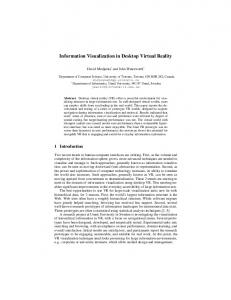
INTRODUCTION Support structures are a necessary evil of many rapid prototyping or free form fabrication technologies. Typically, some support is needed to raise the object from the base platform to enable easy removal, and overhangs need support to prevent warpage and sagging. The support generation has been studied by many researchers, and algorithms to generate the support structures exist [7][8]. These algorithms operate on the CAD model and result in a file which is merged with the original CAD model. Too often, algorithms do not consider certain features of complex parts and the support structures can be either missing, or placed in locations that do not really require support. Typically, problems are not discovered until the part is built. Visualizing the support structures and the CAD model is possible on today’s CAD stations. Figure 1 illustrates a view on a two dimensional screen of an object supported and ready to be sliced.
This image is a screen capture of the CIDES package developed at Clemson to manipulate CAD files and prepare them for building on an RP machine [9]. One limitation of this and all existing environments is the two dimensional representation of a three dimensional object. Rotating an object on the screen cannot be compared to having a prototype in hand and coordinating the eye – hand relationship to detect potential problems. Virtual Reality removes the two dimensional representation barrier and allows the designer to hold a virtual object represented in a CAD drawing, to rotate it, to illuminate it where needed and to detect errors and hopefully correct the errors stemming from support structures, all in three dimensions.
Figure 1. View of Object With Support on 2D Screen Presently, at Clemson University, an object designed on a CAD system and prepared for the rapid prototyping environment, i.e. formatted in the industry standard STL format, can be directly translated and displayed in a virtual environment. The ability to visualize the CAD prototype in the virtual environment, penetrating the prototype, examining it from different angles and eventually manipulating it, offers significant benefits to the designer and to the Rapid Prototyping user. This technology will reduce the time of verification of CAD models before building them on the RP systems. Our objective is to eventually develop tools to identify missing support structures, to add support structures where needed, and to remove useless support structures from the final model. Clear-
ly, we are not yet at this stage, however, with the present interface, the user can verify that the support structure is applied where needed. This paper describes how a link between Virtual Reality and Rapid prototyping was established at Clemson. It discusses some of the issues of translating an STL model into the appropriate format for Virtual Reality. It also speculates on the potential impact of the technology on Rapid Prototyping.
PREVIOUS WORK Virtual Reality is a concept which is very attractive to magazines such as Popular Science, Popular Mechanics, and Science. Speculations about its usefulness and its impact on our lives are rampant, and the burgeoning of journals and magazines devoted to the subject shows its appeal to the community at large. Articles dealing with Virtual Reality and engineering report on the issues of training [1, 2, 3], flow visualization (wind tunnel and flow visualization)[4], maintenance [5], ergonomics and some applications of CAD[6]. The issues of virtual reality and manufacturing are mentioned in a number of articles [2, 3, 6], but technical papers are scarce. Training using Virtual Reality is the realm of defense related activities. The US Navy, the Air Force and other services, use VR based flight simulators to train pilots; battlefield simulations were developed using actual terrain data during Desert Storm. [1, 2, 3] Potential applications to train automobile drivers and pilots using the technology are proposed, probably under development and possibly used in a number of sites. The reference on Caterpillar’s use of CAD based models for training [6] shows the potential of the technology. Users test virtual models before the prototypes are built. This virtual testing process allows the designer to study the ergonomics of novel designs and modify the models if needed to satisfy the customer or user. Boeing’s work on design and maintenance using virtual reality [5] on the Boeing 777 has been described and talked about in a number of magazines, newspapers and articles on the Internet. They used the virtual environment to ensure that parts could be accessed and easily removed during maintenance. The plane is reputed to be the first aircraft designed without the use of a full physical mock– up. Applications of computer aided design (CAD) in a virtual environment are practically non–existent. Trego and Magleby [11] described attempts at connecting a power glove to an existing CAD system (Parasolids). They pointed to the ability to interface with a CAD system and identified weaknesses in the glove interface. Their work is the first work directed towards providing a better inter face to CAD systems using some of the VR technology. Their expectations of the technology are very high. They illustrated the ability to generate free form surfaces from hand motions in the virtual space. Dai [12] from the Frauhofer Institute in Germany showed how a virtual glove could be used to affect surfaces in a virtual environment. The glove was used to modify the shape of cubes by either pushing on the surface, or by using the glove as a tool to shape a block that seemed to be made out of play–dough. Both discussed accuracy problems in the operations in the virtual environment, but indicated the need to pursue research in the area. Sandy Ressler from NIST published a report [13]
on the application of virtual reality to Manufacturing. The examples cited earlier are all summarized in this report. A very recent report from the National Academy of Sciences (Sept 20, 1994 news release on internet) recommends the government should “vigorously pursue a broad–based program of research in virtual environments” that go well beyond those available in the entertainment industry. The report identifies four areas that show the most promise: training, hazardous operations, medicine and healthcare, and design, manufacturing and marketing. This paper targets the fourth area, the one which directly affects industry and productivity. In the area of software support for Rapid Prototyping, a wealth of information is available. The authors and their colleagues at Clemson University were involved in several papers related to support generation [7][8], optimal orientation[10][14]. These efforts show the significance of the support issue. Thus, any tool that helps the designer get a better understanding of the part, of the support needed to build the part, contributes to the shortening of the time to market and results in an improvement in the quality of the built object. The paper illustrates next some of the capabilities of the Virtual environment and then explains the procedure used to convert an STL file to a VR formatted file before commenting on the significance of the work and its benefit to industry.
IMPLEMENTATION Rapid Prototyping is the result of a desire to build parts by material addition rather than subtraction, and to control the machine that makes the parts directly from the computer. In order to achieve this goal, geometric modelers (surface based and solid based) were given the capability to generate files that are easy to operate mathematically upon. The tessellation representation is one that approximates a surface by a number of triangles of various sizes. Once this approximation is performed, it is relatively straightforward to generate slices that represent the intersection of the triangles with a horizontal plane, and surfaces inside a solid can be hatched to solidify a resin or sinter a powder. Presently, an object designed on a CAD system and prepared for the rapid prototyping environment, i.e. formatted in the industry standard STL format, can be directly translated and displayed in the virtual environment. Why would such a feature attract designers and manufacturing engineers? Because of the ability of the brain to interact with visual information without input from the hands. The user is immersed in the object, he or she can walk around it, inside the object, look up, down, sideways, and see features that are not directly accessible using two dimensional representations of a three dimensional object.
THE VR / STL CONNECTION Translating an object from the STL format generated by CAD systems to the VR space is facilitated by the wealth of information held in the STL file format. A STL file consists of a list of triangles in 3D–space. Each triangle definition contains coordinates in 3D–space for each point of the triangle as well as a 3D–space vector defining the normal of the triangle (Figure 2). This format
is ideal for Virtual Reality since the representation of objects in VR is itself a tessellated representation.
... facet normal outer loop vertex vertex vertex endloop endfacet ...
0.000000e+00 0.000000e+00 1.000000e+00 2.029000e+00 1.628000e+00 9.109999e–01 2.229000e+00 1.628000e+00 9.109999e–01 2.229000e+00 1.672000e+00 9.109999e–01
Figure 2. Example ASCII STL File.
The VR application reads in the STL file consisting of a list of triangles which represent the object to be built in rapid prototyping. Note that the three points are given in order to specify the direction of the outward normal. The right hand rule is used. First, minimum and maximum points (in x, y and z) for the object are calculated for scaling and translation purposes. The triangles are then translated and scaled such that (0,0,2) becomes the center of the object and the object fits into a 4x4x4 cube. The unit is not important, but to get an idea of the size of an object, the space represents a four foot cube volume. The Z dimension originates at the transmitter which is located above the person in the middle of a room and points downwards towards the floor. Translating the object has the effect of centering it in the VR space, just below the tracking transmitter at the user eye level. Scaling the object to fit the VR space tracking range is necessary such that all objects do not extend beyond the ability to track the users movements, and are large enough to be useful to the user. OpenGL is used for all the VR graphics. OpenGL directional lights are positioned beyond the VR tracking range (a distance of 10 from (0,0,0)), and pointed toward the object center (0,0,2). The triangles are drawn using an OpenGL compiled call list to facilitate real time updates. This has the effect of imposing static lighting model on the object while still allowing real time changes of eyepoint and viewport. As the users movements are tracked in real space, coordinates representing the users position and vectors representing the users pitch, roll, and yaw are passed via a serial port to the computer. This input is fed to OpenGL calls to change the eyepoint and viewport, and then the OpenGL com-
piled list is called to redraw the object in VR space (Figure 3). This code shows the power and simplicity of the OpenGL code, this is all what is needed to update the image when the user turns the head to point to some other point. The image is recalculated and then sent to the user’s head mounted display. Using a Silicon Graphics Onyx as the compute engine, a rate of well above 30 updates per second for objects consisting of 45,000 triangles or less can be maintained. Above 45,000 triangles the refresh rate drops to below 30 updates a second; but despite the apparent lag, the system is still quite usable. ––– lookatpoint_draw_stl(eye, lap, viewup, list) float eye[3], lap[3], viewup[3]; int list; { int i; glMatrixMode(GL_PROJECTION); glPushMatrix(); gluLookAt (eye[0], eye[1], eye[2], lap[0], lap[1], lap[2], viewup[0], viewup[1], viewup[2]); for (i = 0 ; i < number_objects; i++) glCallList(i+1); glPopMatrix(); } –––
Figure 3. C Code for VR View Updates. In order to allow the user to distinguish between the original part and the support structure, color coding is used. Essentially, different colors are used for the part and the support which provides the user with the visual feedback needed to identify the location of added structure. Figure 6. illustrates the fan object shown in figure 1 as seen from within the virtual space. In this case, the user can basically place his or her head inside the part and make sure the support is located where needed. Missing support is also very quickly identified and the feedback can be used to modify the support generation program. Once the object is appropriately scaled and positioned, the user wears the head mounted display (HMD) which is basically two screens, one for each eye, each one displaying a slightly different view of the object to give a 3D effect. The head mounted display has an emitter mounted on top. The position and orientation of the head is then captured by a stationary receiver, and this information is used to recompute the view point and direction for the image. A recent addition to the system allows us to hold a three dimensional mouse. The mouse operates on the same principle as the HMD,
Figure 4. View from Below the Support Structure in the VR environment and by orienting the mouse, and depressing mouse buttons, the user can fly through a virtual object. How is this information used to interact with the object? Presently, the user can examine an object from any side, inside or out. To interface with the STL file, we are modifying the file structure such that each point is represented uniquely, with the appropriate pointers to the triangles formed by the points. Once this is accomplished, the mouse will be used to point to a particular point in the 3D space. The original point or triangle identified will be flagged in the modified STL file, and the correction will be done subsequently.
SIGNIFICANCE AND BENEFITS Holding an object in one’s hand, and rotating it in order to study it, to understand the way it is assembled or designed can only be performed with a physical prototype. The CAD representation of a design on a computer screen, even three dimensional and solid based, is far from giving the designer the visual to hand coordination needed to truly assess a design. We propose the development of a true 3D CAD CSG system for mechanical design. The system is based on a virtual environment in which the user creates solids by performing solid operations as on a CAD system. These solids are however created like an assembly of building blocks in a three dimensional virtual environment.
The ability to visualize the CAD prototype in the virtual environment, penetrating the prototype, examining it from different angles and eventually manipulating it, offers significant benefits to the designer and to the mold maker or tool maker. This technology will reduce the time of market of products by drastically reducing if not eliminating the iterative process of design and manufacturing. The designer can not only study the part he or she is designing, but also try fitting it, design tools to make the part, and ensure that the prototype is as close to the final product as possible. In this area of design and manufacturing, rapid prototyping processes have established themselves as essential contributors to the quest to produce parts rapidly. Whether parts are directly formed in the RP machines, or molds are created from the RP parts, the time to market of a product has the potential to be significantly reduced. This technology gives the designer more time to mature the product and reduces if not eliminates the communication gap between design and manufacturing. Issues of accuracy, materials, and size are still, and will continue to be researched to improve the parts manufactured, but the available technology is producing results today. The link between computer aided design (CAD), specifically in a Virtual Environment and RP significantly enhances the designer’s productivity.
BIBLIOGRAPHY [1] Kozak, J.J., Hancock, P.A., Arthur, E.J. and Chrysler, S.T. “Transfer of Training from Virtual Reality” Ergonomics, 1993, Vol 36, No.7, 777–784 [2] Bricken, M. “Virtual Reality Learning Environments: Potentials and Challenges.” Human Interface Technology Laboratory, University of Washington, Seattle, WA, 1991. [3] Nash, I. “Visions for a Braver World. Virtual Reality Computer Simulations as an Aid to Teaching Science”. Times Educational Supplement, n.3923, p12, Sept 6, 1991. [4] Robertson, G. Card, S., Mackinlay, J. “The Information Visualizer.” Proceedings of CHI 91. ACM, NY. pp 181–188, 1991. [5] Adam, J. A., “Virtual Reality is for Real” IEEE Spectrum Magazine, Vol 30, No 10, October 1993, pp 22–29. [6] Tanner, S., Miller, K. “The use of High Fidelity CAD Models as the Basis for Training on Complex Systems”, Proceedings of the 1993 conference on Intelligent Computer–Aided Training and Virtual Environment Technology, NASA Houston, [7] Kirschman, C. F., Jara–Almonte, C.C., Bagchi, A., Dooley. R.L. and Ogale, A.A. “Computer Aided Design of Support Structures for Stereolithographic Components” Proceedings of the 1991 ASME Computers In Engineering Conference, Santa Clara, pp 443–448, August 1991. [8] Kirschman, C. F., Namboodri, C., Jara–Almonte, C.C., Bagchi, A., Dooley. R.L. and Ogale, A.A. “Stereolithographic Support Structure Design for Rapid Prototyping” Proceedings of the Second Rapid Prototyping Technology Conference, Dayton OH, June 1991. [9] Kirschman, C.F., Jara–Almonte, C.C., Bagchi, A., Dooley. R.L. and Ogale, A.A. “The Clemson Intelligent Design Environment for Stereolithography” Proceedings of the Second Rapid Prototyping Technology Conference, Dayton OH, June 1991.
[10] Frank, D., Fadel, G. M., “Preferred Direction of Build for Rapid Prototyping Processes”, Presented at the Fifth Rapid Prototyping Technology Conference, Dayton OH, June 1994. Accepted for publication in the Journal of Intelligent Manufacturing, Sept, 1994. [11] Trego, A. and Magleby, S. “Virtual Reality Promises New Design Capabilities”, Proceedings of the ASME International Computers in Engineering Conference, Minneapolis, September, 1994. [12] Dai, F. and Gobel, M. “Virtual Prototyping – An Approach Using VR Techniques”, Proceedings of the ASME International Computers in Engineering Conference, Minneapolis, September, 1994. [13] Ressler, S. “Applying Virtual Environments to Manufacturing” NISTIR 5343, 1994 [14] Bablani, M. and Bagchi, A. “Quantification of errors in Rapid Prototyping Processes and Dtermination of Preferred Orientation of Parts” Paper Accepted for Publication in Transactions of the North American Manufacturing Research Institution of SME, Vol XXIII, 1995.