www.ccsenet.org/cis
Computer and Information Science
Vol. 3, No. 3; August 2010
Supporting Differentiated Service in Cognitive Radio Wireless Mesh Networks Kiam Cheng How (Corresponding author) PhD Candidate School of Electrical and Electronic Engineering, Nanyang Technological University 50 Nanyang Avenue, Singapore 639798 E-mail:
[email protected] Abstract The MAC layer protocols utilizing enhanced distributed channel access (EDCA) in the recently published IEEE 802.11-2007 are able to provide differentiated QoS for different traffic types in wireless networks through varying the Arbitration Inter-Frame Spaces (AIFS) and contention window sizes. However, the performance of high priority traffic can be seriously degraded in the presence of strong noise over the wireless channels. The noise problem is further aggravated in wireless mesh networks when packets traverse multiple-hops from source to destination. The noise problem can be mitigated by distributing network traffic across multiple vacant channels to reduce the node density per transmission channel. Although multiple non-overlapped channels exist in the 2.4GHz and 5GHz spectrum, most IEEE 802.11-based multi-hop ad hoc networks today use only a single channel at anytime. As a result, these networks cannot fully exploit the aggregate bandwidth available in the radio spectrum provisioned by the standards. In this paper, we propose the Power-Controlled Rate-Adaptive MAC (CPCRA) protocol for single transceiver based Cognitive Radio Networks (CRNs) which combines adaptive modulation and coding with dynamic spectrum access. Simulation results demonstrate that CPCRA can achieve better performance in terms of lower delay and higher throughput. Keywords: Cognitive radio, Wireless mesh networks 1. Introduction Wireless mesh networks (WMNs) has been envisioned as a cable-less alternative for broadband wireless Internet access. WMN is composed of radio nodes called mesh routers (MRs) and mesh clients (MCs). The MRs can dynamically self-configure into a mesh topology (Akyildiz & Wang, 2005) and relay the traffic generated by their respective MCs. MRs called Gateway can also be provided with cabled connectivity to the Internet. When one MR fails, the rest of the MRs can still communicate with each other directly or through one or more intermediate MRs. Thus, WMNs provide numerous advantages like extended coverage, network robustness and low cost of deployment. Although WMNs offer an easy and economical alternative for providing broadband wireless Internet access, supporting the diverse quality of service (QoS) requirements of multimedia applications is one of the open issues in the research on WMNs. Specifically, WMNs need to provide different priority to different applications, users, or data flows, or to guarantee a certain level of performance to a data flow. However, WMNs suffer from many shortcomings such as low bandwidth, high error rate and high delay, which prevent them from fulfilling the QoS requirements that are vital to these applications. The broadcast nature of wireless transmissions means that WMNs suffers from the same interference problem that plagues other kinds of wireless networks. The wireless communication medium is also essentially half-duplex; that is, a node cannot listen on the same channel on which it is transmitting at the same time, or the transmitted power signal will jam any packet reception. Additionally, multi-hop wireless networks like WMNs accentuate the interference problem as a multi-hop route requires more transmissions as compared to a single-hop connection (Nandiraju, Nandiraju, Santhanam, He, Wang & Agrawal, 2007). There have been many efforts to improve QoS provisioning capabilities in IEEE 802.11 based networks (Lee, Liao, Chen & Lee, 2009; Xiao, 2006). The most recently published IEEE 802.11-2007 (IEEE, 2007) also provided the enhanced distributed channel access (EDCA) which is a QoS extension to legacy 802.11 distributed coordinated function (DCF). More recent works (Lee, Liao, Chen & Lee, 2009; Zhao, Wu, Zhang & Zhang, 2008) also seek to improve performance through variations of algorithms by tuning different EDCA parameters. However, these schemes does not grant greater protection to higher priority traffic from interference as noise affects all traffic equally. To minimize the interference problem, schemes utilizing power control or adaptive modulation and coding (AMC) schemes (Ma, Zheng, Zhang, Shao & Fujise, 2006; Pursley & Royster, 2008) were proposed. Increasing
Published by Canadian Center of Science and Education
3
www.ccsenet.org/cis
Computer and Information Science
Vol. 3, No. 3; August 2010
transmission power, lowering the data rate and using a more robust modulation can improve signal quality (SINR) at the receiver, reduce the probability of error (BER) and provide better throughput in the presence of noise. However, these schemes are ineffective when a wireless channel has been overwhelmed by noise. Furthermore, increasing transmission power worsens the interference problem by causing more interference at nodes that are previously out of the transmission range when using a lower transmission power. Dynamic spectrum access (DSA) techniques provided by Cognitive Radio (CR) (Mitola & Maguire, 1999) can be used to mitigate the interference problem. DSA consists of spectrum sensing and spectrum decision. Spectrum sensing identifies unused frequency bands via direct sensing of the frequency band by using a matched filter, energy detector (Ghasemi & Sousa, 2008) or frequency reconfigurable antenna (Ghanem & Kelly, 2009). The sensing reliability can also be greatly increased by using a cooperative algorithm (Shen, Liu, Zeng, Xie, Gao & Liu, 2009). There are numerous researches in the area related to spectrum sensing. In (Chowdhury & Akyildiz, 2008), the authors have devised a scheme to allow nodes equipped with a single tunable transceiver to monitor the primary channels while continuing operation in the secondary band. The monitoring is done by measuring the aggregated received power on a node and then isolating the leakage power for each transmitter. However it requires the MRs to be aware of the location of other MRs which might not be feasible in the real-world implementation. Our scheme makes use of the variable relay sensing scheme proposed in (Ganesan, Li, Bing & Li, 2008) for spectrum sensing. This scheme is particularly suitable to be implemented in WMNs as MCs can be employed as cognitive users distributed at various locations as relays to sense data and to improve detection capabilities. Spectrum decision is performed to select the best spectrum band among the available bands according to the QoS requirements of the application. Operating parameters like transmission power, modulation or data rate can be reconfigured to access the new frequency spectrum (Akyildiz, Lee, Vuran, & Mohanty, 2008). Since throughput capacity per node reduces significantly when the node density increases (Gupta & Kumar, 2000), we leverage on existing DSA techniques to identify underutilized portions of the spectrum (Webb, 2009) to carry traffic in the WMN. This reduces the node density per transmission channel and interference, thus improving throughput and delay. In this paper, we investigate the issue of the differentiated service provisioning by adopting a strategy of AMC and DSA in cognitive radio based WMNs or CRNs. The major contributions produced from this work can be summarized as 1) hierarchical adaptive CPCRA MAC Protocol by which nodes can provide a differentiated service for different types of traffic by varying the transmission power to increase the signal to interference/noise ratio according to different traffic priorities, 2) identifies vacant frequency spectrum and distributes traffic to the identified frequency spectrum when desired data rate is unattainable via power control and 3) supports concurrent transmissions in a given interference region using only a single transceiver. To the best of our knowledge, the CPCRA scheme is the first and only scheme that can provide differentiated service for a CRN with only a single transceiver. The rest of the paper is organized as follows. Section 2 describes the system model. Section 3 presents the detailed operations of the CPCRA scheme. Section 4 evaluates the performance of the CPCRA scheme. Section 5 concludes the paper. 2. System Model 2.1 Network Model We consider a multi-hop CRN consisting of N MRs. One MR is randomly selected as a gateway. Packets are forwarded in a multi-hop fashion to or from the gateway. Each MR is equipped with one tunable radio transceiver. Each transceiver is made up of a transmitter-receiver pair and can be configured with different parameters like transmission power, frequency, modulation and data rate. The hardware capability to operate at two different frequencies on a single transceiver simultaneously is already present (Gu, 2005) in many wireless devices. E.g., GSM phones etc. As existing IEEE802.11 network interface cards do not have the above mentioned capabilities, this functionality can be built easily into future “cognitive versions” of the IEEE 802.11 network interface cards. This is not unreasonable considering that cognitive radio technology is rapidly evolving. For ease of explanation and without loss of generality, we consider unidirectional traffic, i.e., the traffic that only goes from the MRs to the gateway. We consider the case where applications with 3 different priorities (c1, c2 and c3) are deployed in the network. 2.2 Physical Layer We assume a physical layer similar to the 802.11a standard with a total of 12 non-overlapping wireless channels
4
ISSN 1913-8989
E-ISSN 1913-8997
www.ccsenet.org/cis
Computer and Information Science
Vol. 3, No. 3; August 2010
and the time needed for channel switching is in the order of milliseconds (Skalli, Ghosh, Das, Lenzini & Conti, 2007). The modulation scheme used is orthogonal frequency-division multiplexing (OFDM) with data rates of 6, 9, 12, 18, 24, 36, 48, and 54 Mbps. Power control is utilized to provide a differentiated service for different traffic priorities. For a pair of transmission between transmitting node i and receiving node j to be successful, N SINRij = ⎛⎜ Pi Gij /( N 0 + ∑ k =1 Pk G kj ) ⎞⎟ ≥ γ * i, j = 1,2,.., N , i ≠ j k ≠i ⎝ ⎠
(1)
where Pi denotes the transmission power of node i, Gij denotes the link gain from node i to node j, N0 denotes thermal noise of node j.
The received SINR at node j, SINRij must be greater than or equal to the minimum required threshold γ . *
As shown in Table 1, our scheme transmits packets belonging to higher priority at higher power. This result in better SINR at the receiver, thus achieving higher data rates compared to the lower priority traffic. 2.3 MAC Layer We extend the RTS/CTS exchange scheme based on the MAC layer protocol of the IEEE 802.11 standard to support the operation of our proposed CPCRA protocol. We modify the RTS/CTS packets to carry additional information used by CPCRA. The information is also stored in neighbor information cache (see Table 2) local to each node. The format of the RTS/CTS packets are described as below. RTS: This message is sent by the sender onto the channel of the intended recipient before the start of a transmission. It contains the sender’s ID, sender’s receiving channel Fs, receiver’s ID, length of the data packet to be transmitted L and priority c. The sender’s receiving channel is needed so that the receiver knows which channel to transmit the corresponding CTS. Upon receiving the RTS, the receiver stores the sender ID and its receiving channel Fs into its neighbor information cache. CTS: This message is sent by the receiver onto the channel of the sender. It contains the sender’s ID, receiver’s ID, supported data rate R, required power P and receiving frequency Fr. Upon receiving the CTS, the sender stores the receiver ID and its receiving channel Fr into its neighbor information cache. Ack: This message is sent by the sender. It contains the agreed upon channel properties for transmission, supported data rate R, power P and frequency Fr. FC: This message is sent by the receiver to its neighbors after changing its receiving frequency. It contains its ID and the new receiving frequency Fr. Upon receiving the FC messages, the ID and receiving frequency Fr are stored into the receiving node’s neighbor information cache. Since different nodes in the CRN operate in different frequency channels, it is plausible that a node is unable to sense or receive control messages from other channels. Thus the concern is how to correctly implement the CSMA scheme needed for the IEEE802.11 standard. In the current implementation of our scheme, the MAC protocol does not get control or network allocation vector (NAV) messages from other channels. However, as the spectrum sensing module identifies only vacant channels to be used for the communication, when a transmission is migrated to a “new frequency”, there is a minimal chance of a collision. As the overall primary user detection probability is
1 p = Pp
∫
∞ 0
p (γ ) e
−
γ P
p
dγ
for a given channel realization γ and average received power Pp, the collision occurs when the channel is occupied but is wrongly identified as being vacant or 1-p. The analysis of this is beyond the scope of this paper and the interested reader can refer to Ganesan, Li, Bing & Li (2008). For our work, we assume the collision probability to be effectively zero. The potential performance improvement by allowing concurrent transmissions outweighs the problem of not keeping track of NAVs from other channels. Nevertheless, in order to further minimize the hidden terminal problem, we can extend the variable relay sensing scheme (Ganesan, Li, Bing & Li, 2008) to sense the control messages from other channels. This can then be updated into the nodes’ neighbor information cache. 2.4 Capacity Analysis There have been some significant research results on the capacity of wireless networks. In Gupta & Kumar (2000), the analytical lower and upper bounds of wireless ad-hoc networks can be determined for the stationary case. The throughput capacity per node reduces significantly when the node density increases, such that Published by Canadian Center of Science and Education
5
www.ccsenet.org/cis
Computer and Information Science
Vol. 3, No. 3; August 2010
it is Ο( 1 ) , where n is the number of nodes. This result, however, can not be applied directly in the n
case of WMNs. This is because in ad-hoc networks, traffic flows between arbitrary pairs of nodes. In contrast, for WMNs, practically all the traffic is either to or from the gateway. This introduces hot spots in the network that act as bottlenecks. Due to the presence of these bottlenecks, the available capacity for each node is further reduced to Ο( 1 ) ( Jun & Sichitiu, 2003), where n is the number of users for n
one gateway. In our analysis, we determine and compare the network forwarding capacity of the proposed CPCRA scheme with traditional WMN. The network forwarding capacity of a network is the sum of link capacity that can be utilized in a time period. To generalize, in a given topology, let F be the set of non-overlapping usable channels. Each node can operate in any 1 out of |F| frequency channels. We define the frequency interference region by the interference range of each transmission at a frequency f, where f ∈ F , such that only one link in a given frequency interference region can be active at any time, and all other links have to be inactive. For example, Fig. 1 shows the interference region (shaded) for the link S2↔S4 for both |F|=1 and |F|=5. The case where only the node furthest from the gateway generates traffic to be sent to the gateway was analyzed. The transmission range is considered to be the distance of one hop when transmitting at the nominal power level, and that the interference range is the same. We consider the case where there is only one gateway in the network and all nodes have same forwarding capacity of C. In the diagrams used below, the pattern of the boundary of the nodes indicates their receiving frequency. 2.4.1 Chain Topology In a traditional WMN, all nodes are on the same frequency interference region, i.e., |F|=1. When a source node transmits data to the gateway, it has to compete with its intermediate downstream node for transmission time by using the RTS/CTS. We can show that for a chain of N nodes, at steady state, the maximum forwarding capacity is NC/3. This gives a low utilization of about 33%. The lack of opportunity for spatial reuse is the main reason for the poor performance in WMNs. For CPCRA, the optimum forwarding capacity occurs when each node operates on a different frequency as its immediate 2-hop neighbors, i.e., |F|=3. In this case, the maximum forwarding capacity is NC/2, which is 1.5 times more than the traditional WMNs. 2.4.2 Arbitrary Topology Fig. 2 shows an arbitrary topology for a WMN and |F|=1. Two source nodes S1 and S3 have data to transmit. To simplify the analysis, we assume that the route taken for data transmitted from S1 go through node S2, S4 and S6. The route taken for data transmitted from S3 will go through S5 and S6. As the nodes are all in the same frequency interference region, at the steady state, there can only be 1 or 2 nodes concurrently forwarding traffic. Fig. 3 shows the same topology for CPCRA. Better performance can be achieved when each node’s receiving frequency is different from every of its immediate 2-hop neighbors, where |F|=5. At the steady state, there can be 3 nodes forwarding traffic concurrently, which greatly improves performance compared to the traditional WMNs. 3. Proposed Scheme 3.1 Overview With the support of CR technique and the previous work on the power-controlled rate-adaptive MAC scheme (Ma, Zheng, Zhang, Shao & Fujise, 2006), we have come up with the idea to design a hierarchical adaptive MAC protocol, CPCRA. The major key point of the CPCRA scheme is that if AMC alone is sufficient to satisfy the minimum SINR threshold of the required data transmission rate, then only AMC feature will be activated. Otherwise, the cognitive module will identify a vacant channel to support the required data transmission rate. This has several advantages. Firstly, costly tuning delay is avoided by utilizing AMC as a primary option. Secondly, vacant channels are identified to support the data transmission rate required by high priority traffic when AMC is insufficient. The operation of the CPCRA scheme can be described as following. When a node is going to start its transmission, it negotiates with the intended receiver by sending a RTS (on the receiver’s receiving frequency) that contains the priority of the next data transmission. The receiver receives the RTS, measures the SINR and calculates the transmission power required to support the requested priority. If the required transmission power is less than the maximum threshold Pmax, it sends a CTS packet (on the sender’s receiving frequency) with the supported data rate and the required transmission power. Otherwise, the receiver performs spectrum sensing to
6
ISSN 1913-8989
E-ISSN 1913-8997
www.ccsenet.org/cis
Computer and Information Science
Vol. 3, No. 3; August 2010
locate a vacant channel that can support the requested data rate and corresponding traffic with its priority. The receiver replies with a CTS containing information on the new channel, supported data rate and required transmission power. The sender acknowledges with an ACK packet after receiving the CTS. The receiver then switches to the new channel. The sender adjusts the transmission power and transmits the packet at the supported data rate, and at the new frequency if necessary. To maintain the receiver’s connectivity to the WMN, the new receiving frequency will be sent and cache on the receiver’s neighboring nodes for future communication. 3.2 Detailed Operation The CPCRA Scheme is depicted in Fig. 4. In the normal mode, the MAC layer adjusts the transmission power to reach the desired data transmission rates according to the requested priority and prevailing SINR. In cognitive transmission, additional steps are performed when the current channel is not able to provide the required data rate requested at the prevailing SINR. The details of each step of the operations can be described as follows. Step 1 Interference Estimation: From (1), the receiver calculates the current SINR. CPCRA then calculates an average SINR value based on a window of previously measured SINR values. This is calculated as:
SINR ave = (1 − w q ) SINR ave + w q SINR where SINR is the current SINR measured and wq is the weight assigned to the current SINR measured. Step 2 Power Control: From (1), we calculate the required transmission power P, with reference of the relationship between the SINR and data transmission rate specified in Table 1. Although power control can be used to increase data rate, the network interface card has a limit to the maximum transmission power Pmax. This diminishes the effectiveness of power control in the presence of heavy noise as P must be smaller than Pmax. To overcome this, the transmission can be migrated to a new frequency where there is less noise. We model the power control problem as follows. Let Mi represents the available modulation schemes with corresponding data transmission rate, Ri and SINR threshold γ i * at which BER(Mi) = 10-5, i = 0, 1, ..., 7. Packets with priority c1 can be transmitted at transmission rate Ki (i = 4, 5, 6, 7); packets with priority c2 will be transmitted at transmission rate Kj (j = 2, 3, 4, 5) and packets with the priority c3 can be transmitted at the transmission rate Kk (k = 0, 1, 2, 3), and i > j > k. The complete procedure of transmitting a packet by the proposed scheme can be described as follows: 2_1: When a node Src has a packet for a node Des, it transmits the RTS packet containing the length of the data packet and priority ck, The RTS will be transmitted at basic data rate K0 and basic transmission power P0. If not, it defers its transmission controlled by the DCF scheme in IEEE 802.11. 2_2: When Des receives the RTS successfully, it measures the SINR of the received signal. Depending on the priority ck, it seeks the SINR threshold γ i * of the maximum supported data transmission rate for ck, Ki. The required power P can be calculated as
P = Max( P0 × γ i * /SINR, rxsensitivity ( K i ) × PRTS / PrRTS )
(2)
where rxsensitivity(Ki) is the receiving sensitivity of rate Ki, PRTS is the transmission power of RTS. PrRTS is the received signal strength of RTS after attenuation. 2_3: If P ≤ Pmax , A CTS packet will be sent to Src with the supported data rate R and required power P. End of procedure. 2_4: If P > Pmax , Check that the data transmission rate Ki-1 for the previous level supports the requested priority. Recalculate the power needed for keeping the corresponding transmission rate using (2). Go to Step 3. 2_5: If transmission at basic data transmission rate K0 is not possible, or if packet priority is c1 and supported data transmission rate is less than 24 Mbps, go to step 3. Step 3 Spectrum Sensing: Spectrum sensing will be performed to identify an alternative frequency channel Fx. We further assume that a variable relay sensing scheme (Ganesan, Li, Bing & Li, 2008) can be implemented and the mesh clients are able to feedback information for an unused frequency channel to their receivers. Using (2), the power Px that is needed to support the requested data rate Rx in this new frequency channel will be calculated. If Px ≤ Pmax , then
Published by Canadian Center of Science and Education
7
www.ccsenet.org/cis
Computer and Information Science
Vol. 3, No. 3; August 2010
Fx is a viable channel. A CTS packet will be sent to Src with the new frequency Fx, requested data rate Rx and power Px. Step 4 Spectrum Decision: We assume that tuning delay is td s, and the average size of a packet is L bytes. Spectrum decision is performed only when the supportable data rate is very low, e.g. 6Mbps. Assuming a typical throughput of 23Mbps at the unoccupied frequency band (Mahasukhon, Hempel, Song & Sharif, 2007), and q which is the number of high priority packets (c1) waiting at the Src queue, the overall increase in transmission delay to send them at 6Mbps 6 compared to sending them at 23Mbps is (q × L × 8) / 17 × 10 s . To ensure that the tuning delay is smaller than 6 the overall increase in transmission time, q > 2.125 × 10 td / L must be satisfied.
(
)
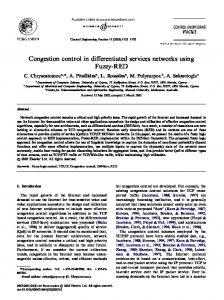
If we assume td = 0.001s (Skalli, Ghosh, Das, Lenzini & Conti, 2007), and packet size L = 512 bytes, then q > 4.15. When there are 5 or more priority c1 packets waiting at the sender queue, it is more worthwhile to incur the tuning delay for channel switching in order to reduce the overall transmission delay. After the channel switch, Des will send out Frequency Change (FC) packets that contains its new receiving frequency Fx to its one hop neighbors. If Des has n one-hop neighbors N1, ..., Nn, with m distinct receiving frequencies F1, ..., Fm, then m FC messages need to be sent, where m ≤ n . Once the FC packets are received, Des’s neighboring nodes will update the state table to indicate the new receiving frequency Fx. All future transmission to node Des will subsequently use the new frequency Fx. 4. Performance Evaluation Simulation experiments have been performed using OPNET to evaluate the performance of the performance of the proposed CPCRA scheme. 4.1 Simulation Setup A scenario with 64 MRs has been considered. The MRs form an 8*8 grid with a distance of 125m between any two neighboring MRs. We performed 10 simulation runs with different random number seed. For each run, a random MR is selected as the gateway and 16 other MRs are selected as traffic sources. The traffic generation is a Poisson process with mean packet inter-arrival time that is exponentially distributed with mean value of 25ms. The packet size is fixed at 512 bytes with three different priorities (c1, c2 and c3). Each priority of packets occupies 1/3 of entire traffic load. Receiver sensitivity is -95dBm, basic transmission power is 7dBm and maximum transmission power is 30dBm. Tuning delay is set as 1ms. We compare the performance of CPCRA with 2 other schemes to show the benefit of CPCRA. These schemes are (i) 802.11a based traditional WMN with Power Control (WMN-PC) (Ma, Zheng, Zhang, Shao & Fujise, 2006) and (ii) 802.11a based single interface CR-WMN (Thoppian, Venkatesan & Prakash, 2007). For (i), there is no spectrum sensing and decision when the requested data rate is not supported. Instead, the lowest data rate (6 Mbps) will be used. For (ii), we assumed that spectrum decision is initiated when supported data rate drops below 18 Mbps. The three major metrics for performance evaluation are single-hop average packet delay, network throughput and average transmission power. 4.2 Simulation Results The simulation results in Fig. 5 show that packets experiences less delay by the CPCRA compared to other schemes under various traffic loads. CR-WMN performs poorly due to the need to switch back to the common control channel after every transmission. There are also some link breakages when a node switches among channels frequently. Furthermore, there is no delay differentiation for different traffic classes. CPCRA also performs much better compared to WMN-PC because the CPCRA can transmit across different frequency channels with higher data transmission rate when the current channel is under much noise. CPCRA can also provide clear delay differentiation for different traffic classes with higher priority traffic experiencing lower delay. This is because higher priority traffic has been sent at higher data rates compared to lower priority traffic. Fig. 6 shows that CPCRA outperforms other 2 schemes under various traffic loads. When traffic load is 1.4Mbps, CPCRA has 14% and 36% higher throughput compared to WMN-PC and CR-WMN, respectively. Fig. 7 shows the average transmitting power for the 3 schemes under various traffic loads. When traffic load is 1.4Mbps, WMN-PC transmits at an average power of 14.8 dBm whereas CPCRA’s average transmitting power was 7.9 dBm. The reason for the higher power consumption for WMN-PC is that as transmission power increases, it interferes with the reception of packets at remote nodes, causing them to increase their transmitting power to compensate for the increased noise. This causes even more collisions and average transmitting power
8
ISSN 1913-8989
E-ISSN 1913-8997
www.ccsenet.org/cis
Computer and Information Science
Vol. 3, No. 3; August 2010
begins to spiral uncontrollably towards the maximum allowable power. CPCRA will not suffer from this shortcoming as it is able to spread the traffic load onto other channels. Fig. 8 shows the total protocol overheads for the 3 schemes under various traffic loads. This measures the overhead generated by the RTS/CTS and ACK packets and reflects the efficiency of the protocols. Under all traffic loads, the overheads for the CPCRA scheme are higher than that of the other two schemes. This is due to the additional control packets that are required for channel switching and updates. However, the volume of the control packets generally does not exceed 10% of the total traffic generated. 5. Conclusion In this paper, we have proposed a Power Controlled Rate Adaptive for single transceiver based CRNs (CPCRA) to support differentiated service in WMNs. Our scheme combines two approaches, AMC and DSA provided by cognitive radio technology. The simulation results have indicated that the proposed CPCRA scheme can provide a significant performance improvement in terms of lower delay and higher throughput at only a slight increase of transmission power and protocol overheads. CPCRA can also provide clear service differentiations for different traffic classes in under all traffic loads. In the future, we will extend our work by implementing an interference-aware routing scheme to improve the end-to-end network performance with consideration of the overall network topology, traffic types and volume. References Akyildiz, I.F., Lee, W.-Y., Vuran, M.C., and Mohanty, S. (2008). A Survey on Spectrum Management in Cognitive Radio Networks. IEEE Communications Magazine, Vol. 46, No.4, Apr. 2008, pp. 40-48. Akyildiz, I.F. and Wang, X. (2005). A Survey on Wireless Mesh Networks. IEEE Communications Magazine, Vol. 43, No.9, Sep. 2005, pp. S23-S30. Chowdhury, K.R. and Akyildiz, I.F. (2008). Cognitive Wireless Mesh Networks with Dynamic Spectrum Access. IEEE Journal on Selected Areas in Communications, Vol. 26, No.1, Jan. 2008, pp. 168-181. Ganesan, G., Li, Y., Bing, B., and Li, S. (2008). Spatiotemporal Sensing in Cognitive Radio Networks. IEEE Journal on Selected Areas in Communications, Vol. 26, No.1, Jan. 2008, pp. 5-12. Ghanem, F., Hall, P.S., and Kelly, J.R. (2009). Two Port Frequency Reconfigurable Antenna for Cognitive Radios. Electronics Letters, Vol. 45, No.11, 2009, pp. 534-536. Ghasemi, A. and Sousa, E.S. (2008). Spectrum Sensing in Cognitive Radio Networks: Requirements, Challenges and Design Trade-offs. IEEE Communications Magazine, Vol. 46, No.4, Apr. 2008, pp. 32-39. Gu, Q. (2005). RF System Design of Transceivers for Wireless Communications. Springer. Gupta, P. and Kumar, P.R. (2000). The Capacity of Wireless Networks. IEEE Transactions on Information Theory, Vol. 46, No.2, Mar. 2000, pp. 388-404. IEEE (2007). IEEE 802.11 LAN/MAN http://standards.ieee.org/getieee802/802.11.html.
Wireless
LANS
[Online]
Available:
Jun, J. and Sichitiu, M.L. (2003). The Nominal Capacity of Wireless Mesh Networks. IEEE Wireless Communications, Vol. 10, No.5, Oct. 2003, pp. 8-14. Lee, J., Liao, W., Chen, J.-M., and Lee, H.-H. (2009). A Practical QoS Solution to Voice Over IP in IEEE 802.11 WLANs. IEEE Communications Magazine, Vol. 47, No.4, 2009, pp. 111-117. Ma, M., Zheng, J., Zhang, Y., Shao, Z., and Fujise, M. (2006). A Power-Controlled Rate-Adaptive MAC Protocol to Support Differentiated Service in Wireless Ad Hoc Networks. Paper presented at IEEE Global Telecommunications Conference, 2006. Mahasukhon, P., Hempel, M., Song, C., and Sharif, H. (2007). Comparison of Throughput Performance for the IEEE 802.11a and 802.11g Networks. Paper presented at International Conference on Advanced Information Networking and Applications. Mitola, J., III and Maguire, G.Q., Jr. (1999). Cognitive radio: making software radios more personal. IEEE Personal Communications, Vol. 6, No.4, Aug. 1999, pp. 13-18. Nandiraju, N., Nandiraju, D., Santhanam, L., He, B., Wang, J., and Agrawal, D.P. (2007). Wireless Mesh Networks: Current Challenges and Future Directions of Web-In-The-Sky. IEEE Wireless Communications, Vol. 14, No.4, Aug. 2007, pp. 79-89. Pursley, M.B. and Royster, T.C. (2008). Low-Complexity Adaptive Transmission for Cognitive Radios in Published by Canadian Center of Science and Education
9
www.ccsenet.org/cis
Computer and Information Science
Vol. 3, No. 3; August 2010
Dynamic Spectrum Access Networks. IEEE Journal on Selected Areas in Communications, Vol. 26, No.1, Jan. 2008, pp. 83-94. Shen, J., Liu, S., Zeng, L., Xie, G., Gao, J., and Liu, Y. (2009). Optimisation of Cooperative Spectrum Sensing in Cognitive Radio Network. IET Communications, Vol. 3, No.7, 2009, pp. 1170-1178. Skalli, H., Ghosh, S., Das, S.K., Lenzini, L., and Conti, M. (2007). Channel Assignment Strategies for Multiradio Wireless Mesh Networks: Issues and Solutions. IEEE Communications Magazine, Vol. 45, No.11, Nov. 2007, pp. 86-95. Thoppian, M., Venkatesan, S., and Prakash, R. (2007). CSMA-Based MAC Protocol For Cognitive Radio Networks. Paper presented at IEEE International Symposium on World of Wireless, Mobile and Multimedia Networks. Webb, W. (2009) Mind the gaps - [comms white space]. Engineering & Technology, Vol. 4, No.8, 2009, pp. 66-69. Xiao, Y. (2006). QoS Guarantee and Provisioning at the Contention-Based Wireless MAC layer in the IEEE 802.11e Wireless LANs. IEEE Wireless Communications, Vol. 13, No.1, 2006, pp. 14-21. Zhao, L., Wu, J.Y., Zhang, H., and Zhang, J. (2008). Integrated Quality-of-Service Differentiation over IEEE 802.11 Wireless LANs. IET Communications, Vol. 2, No.2, 2008, pp. 329-335.
S1
S4
S2
S6
S5
S3
S1
gw
S4
S2
|F|=1
S6
S5
gw
|F|=5
S3
Figure 1. Frequency interference region for S2↔S4 where |F|=1 and |F|=5
10
ISSN 1913-8989
E-ISSN 1913-8997
www.ccsenet.org/cis
S1
Computer and Information Science
S4
S1
c S2 c
S4
gw
S6
Vol. 3, No. 3; August 2010
S2
c S5
S5 S3
S3 S1
gw
S6
S1
S4 S2
S4
c
S2 c
gw
S6
gw
S6
gw
S5
S5 S1 S3
S6
S3
S4
c S2
S6
gw
c
S5 S3
Figure 2. Traffic forwarding scenario for |F|=1
S1
S1
S4 c S2
gw
S6 c
S4 S2
c S5
S5 S3
S3
S1 c
S2 c
c
S1 c
S4 S6
gw
S6
S4
gw
S5
c
S2 S5 S3
S3
Figure 3. Traffic forwarding scenario for |F|=5
Published by Canadian Center of Science and Education
11
www.ccsenet.org/cis
Computer and Information Science
Vol. 3, No. 3; August 2010
CPCRA
Normal Mode
Cognitive Mode
Interference Estimation
Power Control
Spectrum Sensing
Spectrum Decision
Figure 4. CPCRA Scheme 1.30
1.10
CPCRA Priority 3
CPCRA Priority 2
CPCRA Priority 1
WMN-PC Priority 3
WMN-PC Priority 2
WMN-PC Priority 1
CR-WMN Priority 3
CR-WMN Priority 2
CR-WMN WMN Priority 1
Delay (msec)
0.90
0.70
0.50
0.30
0.10 0
200
400
600
800 1000 Offered Load (Kbps)
1200
1400
1600
Figure 5. Delay vs Offered Load 900 CPCRA
800
CR-WMN
700
Throughput (Kbps)
WMN-PC
600 500 400 300 200 100 0 0
200
400
600
800
1000
1200
1400
1600
Offered Load (Kbps)
Figure 6. Throughput vs Offered Load
12
ISSN 1913-8989
E-ISSN 1913-8997
www.ccsenet.org/cis
Computer and Information Science
Vol. 3, No. 3; August 2010
16.00 CPCRA
15.00 Average Transmitting Power (dBm)
WMN-PC 14.00 CR-WMN 13.00 12.00 11.00 10.00 9.00 8.00 7.00 6.00 0
200
400
600
800
1000
1200
1400
1600
Offered Load (Kbps)
Figure 7. Transmission Power vs Offered Load
CPCRA
200.00
Total Protocol Overheads (Kbps)
WMN-PC CR-WMN 150.00
100.00
50.00
0.00
0
200
400
600
800
1000
1200
1400
1600
Offered Load (Kbps)
Figure 8. Total Protocol Overheads vs Offered Load
Published by Canadian Center of Science and Education
13