with good quality; network provider would like to provide value-added services besides the pure transport of best effort traffic; content providers are eager to ...
6XSSRUWLQJ�5693�LQ�D�'LIIHUHQWLDWHG�6HUYLFH�'RPDLQ� DQ�$UFKLWHFWXUDO�)UDPHZRUN�DQG�D�6FDODELOLW\�$QDO\VLV Andrea Detti (*), Marco Listanti (**), Stefano Salsano (*), Luca Veltri (**) (*) CoRiTeL Consorzio di Ricerca sulle Telecomunicazioni Via di Tor Vergata, 135 00133 Roma (Italy)
$EVWUDFW This paper analyzes a framework to offer reservation of resources and QoS guarantees according to the Resource Reservation Protocol (RSVP) paradigm in a network cloud that supports a differentiated services architecture. The key elements are: intelligent Edge Devices; a flow admission and resource allocation method involving an Admission Control Server; “simple” core routers based on the differentiated services model. The main functionality of a client/server protocol between the Edge Devices and the Admission Control Server, called Simple Admission Control Protocol, is described. The proposed framework is referred to as Admission Control Server based Resource Allocation. Scalability is analyzed and compared with RSVP approach.
1.� Introduction The support of QoS is a key challenges for the evolution of the Internet. Several players in the Internet arena are interested in the QoS support. For example end users would like to send and receive their real time traffic (audio, video) with good quality; network provider would like to provide value-added services besides the pure transport of best effort traffic; content providers are eager to have the chance to distribute their video and audio streams over the Internet. The integrated services (int-serv) model [1] has been proposed by the IETF to cater for the support of Quality of Service in the Internet, but it seems that this model will not scale for network topologies bigger that few local routers. The RSVP protocol has been designed to support the int-serv model. Each “QoS flow” is identified within all routers in the path from the origin to the destination, which provide the required resources. The performances of backbone routers are severely affected by this “per-flow” approach. The differentiated services (diff-serv) model ([2,3]) is now under study within IETF. It is a simpler approach, which should not suffer of scalability issues and should scale up to the core routers. The basic idea is to support a set of traffic classes providing a different service to each class. The service model is still under discussion: which kind of services can be provided, which levels of guarantees and so on. The diff-serv approach seems very promising, nevertheless it cannot cover all the needs that led to define the int-serv model and the RSVP protocol. For example, an important difference between the int-serv and diff-serv model is that the former one takes care of end-to-end behaviors in its intrinsic definition, while the latter basically specifies “local” behaviors which must be somehow composed to achieve endto-end significance. It is therefore interesting to consider
This work has been supported in part by the EC in the context of ACTS project ELISA (http://www-st.inf.tu-dresden.de/elisa/).
(**) INFOCOM Dept., University of Roma "La Sapienza" Via Eudossiana, 18 00184 Roma (Italy) solutions for the interoperability of the two approaches. The basic idea, as described in [4] is to have “access” networks working with RSVP and “core” networks based on diff-serv. Section 2 discusses some issues of the differentiated services model and clarifies the diff-serv network features upon which our framework relies. Sections 3 and 4 provide an overview of the architectural framework. Section 5 presents a scalability analysis.
2.� Basic concepts for the interworking of diffserv and RSVP Both int-serv and diff-serv approaches go beyond the besteffort service model and envisage a “service profile”, which defines a kind of agreement between the customer and the network provider. The service profile can be classified according to the spatial granularity and to the temporal flexibility. From the point of view of the spatial granularity, the RSVP-like approach gives the maximum of detail: the flow to which the agreement applies is fully specified from the source point to the destination (and even through its whole path from source to destination). One of the advantages of the differentiated services model is that the service profile can be expressed in a coarser way than in the integrated services model. One customer could simply require that all his/her traffic (or a given fraction of this traffic) would receive a better service (in term of loss probability or transport delay) than common best effort traffic. From the point of view of the temporal flexibility, again the RSVP model foresees dynamic agreements which can be set up and released on demand, starting from the need of the user applications (e.g. real time video and audio transport over the Internet). The diff-serv approach basically supports more static agreements, where the duration of the agreement is defined on a contractual basis between the customer and the provider. This contract is called “Service Level Agreement” (SLA) in the diff-serv terminology. The use of “spatially coarse” and temporary “static” service profiles seems one of the most interesting applications, at least in the short term, of the differentiated services approach. The SLAs usually specifies the amount of traffic of a given class that the customer is allowed to send to the network, thus allowing policing at the edge of the network. The network provider will take a set of possible actions, typically at the network provisioning level, to ensure that enough resources are available for the set of active SLAs. The drawback is that it is not simple, if not impossible, to give quantitative service assurances and achieve high network utilization if the SLAs are coarse in their nature (see also [5]). When the SLA is known with a more precise spatial definition it is simpler to provide deterministic assurance on the given QoS. Let us assume that a SLA specifies the origin,
the destination and the amount of the traffic that must receive a “high quality” service. The network provider can therefore provide adequate resources on the corresponding path where it is needed, and the waste of resource is not anymore a problem. The current IETF work on the differentiated service model is considering this approach under the name of Expedited Forwarding (EF) service. It gives a quantitative bandwidth assurance allowing the support of “virtual leased lines” over an ISP network. The EF service is described in [6], under the name of “Premium” service. It is conceptually simple to provide the EF service. For each router in the path the capacity on each outgoing link allocated for the EF class should always exceed the rate at which the admitted customers can inject traffic. Moreover the occupation of each link due to the EF packets should be reasonably low to make the queuing delay negligible. If the agreement is static, the network provider will typically perform network management actions to configure its network in order to provide the required resource. If the agreement is dynamic, more sophisticated approaches need to be taken into account. In particular dynamic admission control and dynamic resource allocation mechanisms in the diff-serv clod must be defined and implemented. The support of dynamic SLAs for the EF class in a diff-serv cloud enables the provisioning of RSVP based services over a diff-serv cloud. Each RSVP reservation request can be mapped in the establishment of a dynamic diff-serv SLA.
3.� Architectural framework In Figure 1 the general architecture of our framework is shown. The interior of the network is composed by a set of routers that support the diff-serv paradigm. At the border of the network a set of Edge Devices (ED) allow the interworking with RSVP. RSVP messages and related state information are only handled in the EDs, at the network boundary. The internal routers simply ignore RSVP control messages, forwarding them as IP packets.
Control Server (i.e. hierarchies of ACSs, synchronization among ACSs) are beyond the scope of this paper. The ACS operate only at the level of a single Internet Service Provider / autonomous system. The ACS keeps the actual resource allocation of the links in the diff-serv cloud. An ingress ED explicitly asks the ACS for the resources on the path towards an egress ED. If the resources are available, the ACS acknowledges the request and updates its view of the resource allocation. The resources will be explicitly de-allocated by the ED sending a corresponding message to the ACS. We called this mechanism Admission Control Server based Resource Allocation (ACS-RA). We propose a protocol between the EDs and the ACS to support this mechanism, called Simple Admission Control Protocol (SACP). As shown in Figure 2, at the user plane level the ingress ED receives the IP packets related to a given flow, maps them into the appropriate diff-serv class and forwards them into the diff-serv network towards the Egress ED. The diff-serv routers within the cloud forward the IP packets toward the Egress ED, according to diff-serv based scheduling. In the same figure, the control plane establishment procedure is shown. The ingress ED receives RSVP path messages from the RSVP aware sources, stores “PATH state” and forwards the messages towards the destination. The Egress ED will interpret them and forward them toward the destination. The same mechanism applies to RSVP RESV messages, which will be received by the Egress ED and sent to the ingress ED. Upon the reception of the first RESV message related to a given flow the ingress ED will use the SACP protocol to perform the flow admission control procedure with the help of the ACS. If the admission procedure is successful, the ingress ED will send the RESV message towards the sender host. 8VHU�3ODQH '6�5
Classifier, policer, marker
$GPLVVLRQ &RQWURO 6HUYHU Host
(JUHVV�('
,QJUHVV�('
IP packet flow '6�5
'LII�VHUY FORXG
&RQWURO�3ODQH
R
$&6
R ED
5693�EDVHG
ED
SACP Admiss. Resp.
DFFHVV
SACP Admission Req.
QHWZRUNV
DS-R
ED
DS-R
'LII�VHUY
R
ED
'6�5
RSVP Path
R 'LII�VHUY
ED
FORXG
RSVP Resv
ED R
R ED: Edge Device DS-R Diff-Serv Router R: RSVP capable router
User flows SACP protocol RSVP relationship
Figure 1: Architectural framework The admission control procedure for the diff-serv network is performed with the help of an Admission Control Server (ACS). The Admission Control Server functionality is logically centralized, and for simplicity in this paper we will consider a single, physically centralized ACS within a diffserv domain. In a real implementation, the Admission Control Server functionality could be split among a set of coordinated ACSs, for both reliability and load sharing reasons. Anyway, the required enhancements to support a distributed Admission
,QJUHVV�('
FORXG
RSVP Path
(JUHVV�('
RSVP Path
RSVP Resv
RSVP Resv '6�5
Figure 2: Support of RSVP on a diff-serv network Let us now consider the mechanisms and information needed for resource allocations in the ACS-RA framework. In a RSVP capable network the set-up, maintaining and tear-down of flows (soft states) are managed directly by all routers encountered along the path followed by the packets belonging to the flow. On the contrary in the ACS-RA environment, the admission control and resource reservation are managed by the Admission Control Server, externally to the routers. To provide a suitable resource reservation, ACS should know the network state (i.e. the link bandwidth occupations) and the end-to-end path followed by each established flow. A naïve approach could be based on a static knowledge of
response. No correlation exists between the admission request and the release request. Other messages are needed for synchronization and error recovery procedures, for example OLYLQJ� (ED È ACS), UHV\QF�UHTXHVW�(ACS È ED). In the proposed ACS-RA framework, the Admission Control Server keeps information at an aggregate level (per link, per Edge Device), while per flow information is only stored in the Edge Devices. The EDs keep per-flow “soft” state, which is created with the first RSVP RESV message and must be constantly refreshed by RESV messages. The ACS works with “hard” state, that is a resource is allocated once with the SACP DGPLVVLRQ� UHTXHVW message until explicitly deallocated with a UHOHDVH�UHTXHVW message. This approach has a positive impact on the scalability, as it reduces the interactions of EDs with the ACS. An overview of the procedures performed in the EDs and in the ACS, and of the supporting data that must be stored in these elements is given hereafter. To reduce the number of options, from now on it is assumed that the ('�EDVHG�URXWH GLVFRYHU\ approach (see section 3) is used. Figure 3 shows a conceptual diagram of the ED control plane functionality related to the handling of RSVP messages and to the admission control procedures.
Path
Routing path request, answer
(' FRRUGLQDWRU
Resv
Request, update release, etc.
Soft states
7LPHU
6/$ GDWD 7LPHU
4.� The Simple Admission Control Protocol The SACP is a client/server protocol, which allows a client to logically reserve/release resources that are under the control of a server. The SACP protocol relies on TCP, which provides a reliable transport of SACP messages. Two basic message request/response pairs are defined: the DGPLVVLRQ UHTXHVW�UHVSRQVH and the UHOHDVH�UHTXHVW�UHVSRQVH. The DGPLVVLRQ� UHTXHVW message (ED È ACS) contains the following parameters: − Request ID − Ingress point (IP address) − Egress point (IP address) − (Optional) Route Information (list of IP addresses) − Requested Resource (e.g. traffic class, bandwidth) The DGPLVVLRQ�UHVSRQVH message (ACS È ED) contains the following parameters: − Request ID (the same ID contained in the admission request) − Response (ACK/NAK) The UHOHDVH� UHTXHVW (ED È ACS) and UHOHDVH� UHVSRQVH (ACS È ED) messages respectively carry the same parameters of the admission request and release messages. The Request ID is only used to correlate a request with the
5RXWH GDWD
Route evaluation procedure
Diff Serv routers
Release resp
Living Release req
Admiss. req
Admiss. resp
to-from Admission Control Server
Other EDs in the Diff-serv cloud and routers in the RSVP access networks
network topology (assuming that each flow between a pair of ingress and egress EDs follows a prefixed path). Unfortunately, the topology of the network and the paths followed by the packets can dynamically change due to events like failures, load balancing, adding/removing hardware. All these considerations lead to the observation that a crucial task is how to dynamically get route path information (route discovery). There are two different approaches: One approach (FHQWUDOL]HG�URXWH� GLVFRYHU\) foresees that the ACS monitors the network topology. Typical Network Management tools and protocols (e.g. SNMP) could be used to this purpose. Then, during an admission request an ED information about the pair of ingress and egress point passes to the ACS and the ACS calculates the route based on this information. Another approach (('� EDVHG� URXWH� GLVFRYHU\) foresees that each ED evaluates the route towards the egress point and communicates it to the ACS in the admission request. The ED should constantly monitor this information for the set of the active flows. The “refresh” rate of this information should be at least comparable with the average refresh rate of RSVP messages. Different mechanisms can be used. The WUDFHURXWH utility is an application that performs this task (see [7], chapter 3). To record a route with N hops, 2N messages are needed, with a quite lengthy procedure. Approaches have been considered to improve this behavior, for example the procedure described in RFC 1393 [8] needs only N+1 messages and it is faster. Another possibility is the use of the IP option “Record Route”, which requires each router in the path to record its address in a field of the IP header. The Egress ED should read this information and send it back to the ingress ED. Both approaches assume in the diff-serv cloud a “slowly” changing network topology and routing, and that all packets of the same flow follow the same route through the cloud. If the core routers implement load sharing (i.e. a router can use different outgoing links for the same destination), this could be realized taking into account the originating address in the selection of the outgoing link.
Internal interface toward policer, marker, scheduler modules
Figure 3: Edge device control plane The ('BFRRUGLQDWRU module handles the RSVP procedures, correlating them with the admission control procedure performed by means of the SACP; it handles the SACP procedures interacting with the 5RXWHBGDWD module and the 6/$BGDWD module. The 5RXWHBGDWD�module must provide and store route path data. The 5RXWHBGDWD can be seen as cache memory that stores the paths from the ingress ED to the others EDs. This cache is refreshed, using the route discovery procedure, periodically to maintain the consistence between the information stored and the actual route path. The 6/$BGDWD module stores, the flow “soft” state information (Session, Flow_spec, Filter_spec) and its routing path into the diff-serv cloud. When the ED receives a RSVP RESV message related to a new flow, it sends an DGPLVVLRQ� UHTXHVW message to the ACS. According to the DGPLVVLRQ�UHVSRQVH message, the ED forwards either a RSVP RESV message towards the sender or
a RSVP RESV_ERR message towards the receiver otherwise. If a “refresh” RSVP RESV message is received, only the state in the 6/$BGDWD is refreshed. When a RSVP RESV_TEAR message is received, or a timer related to a reservation is expired, a UHOHDVH� UHTXHVW message is sent to the ACS. When a change in the route path of an active flow is detected, the resources on the old path must be released sending a UHOHDVH� UHTXHVW and new resources must be allocated sending an DGPLVVLRQ�UHTXHVW. The ACS functionality (Figure 4) can be decomposed in two modules: $&6BSURFHVVRU and 5$BGDWD (Resource Allocation data). The 5$BGDWD module represents the database of the resources to be allocated. It has a OLQN� XVDJH� DUUD\ in which each link within the diff-serv cloud is associated with a JOREDO� OLQN LQIRUPDWLRQ (i.e. total bandwidth and current available bandwidth) and a vector of OLQN�XVDJH�LQIRUPDWLRQ. Each OLQN XVDJH� LQIRUPDWLRQ� is related to a specific ED and stores the amount of resources used by the ED over the link. Admission req Admission response Release req Release resp Living
$&6 SURFHVVRU 7LPHU
5$ GDWD Links usage array (hard state)
Figure 4: Admission Control Server When an DGPLVVLRQ� UHTXHVW message is received, the $&6BSURFHVVRU module compares the Requested Resource parameter with the available bandwidth on each link of the Route Information parameter. According to the result, it accepts or refuses the incoming request and sends the DGPLVVLRQ� UHVSRQVH message to the requesting ED. If the request is accepted, the $&6BSURFHVVRU updates the OLQNV XVDJH� DUUD\. The resource is allocated until explicitly deallocated by a UHOHDVH�UHTXHVW message. The main reason to store the resource allocated by each ED is the handling of failures in the edge devices. The crash of an edge device causes the inconsistency of the OLQNV�XVDJH�DUUD\ with the real links usage. For this purpose, if there is no other activity, the ED periodically sends a OLYLQJ message to the ACS. If the ACS detects that an ED is not working anymore, it will release the resources that were allocated by the broken ED and clear the associated link usage information. When the ACS suspects that the synchronization of the data related to a single ED can be lost, it can request the ED to send DGPLVVLRQ�UHTXHVW�messages for each active flow in the ED. The UHV\QF�UHTXHVW message is used to this purpose.
5.� Scalability analysis In this chapter we investigate the scalability of ACS-RA in comparison with RSVP approach. It is important to remark that the main advantage of a ACS-RA is the simplicity of the user plane implementation inherited by the diff-serv approach. Therefore, as far as the user plane is concerned the ACS-RA behaves far better than a RSVP based network. For this reason no further investigation is provided on the comparison of the user plane performances. On the other hand we will concentrate on control plane
performance evaluation, trying to compare processing load and memory requirement in both approaches. It is important to note that in this comparison we will assume a single centralized ACS for a given diff-serv cloud. This is obviously the worst case for ACS-RA architecture; nevertheless we will show that it scales better than an RSVP approach with regard to control plane too. 5.1.� Memory requirements Let us compare the memory requirements in the two approaches. We will evaluate first the global amount of memory needed in all network elements, as an indication of the overall complexity. Then the memory allocated in the most loaded network elements, which constitute possible bottleneck, will be compared. We denote: − )6,: flow state information; − 53,: routing path information in the diff-serv cloud; − 1): number of flows in the diff-serv cloud. − 3/: path length, i.e. the mean number of routers along the path of a flow in the diff-serv cloud, including ingress and egress EDs. − 1/: number of links of the diff-serv cloud. − /6,: link state information. − 1(': total number of EDs in the diff-serv cloud. We indicate with [[] the number of bytes used to store the information [. In RSVP for each active flow the FSI is stored in all routers along the path; therefore the total amount of memory is: PL.[FSI].NF (1) For ACS-RA the memory used in the EDs is: NF.( [)6,] + [53,]) while the memory used in the OLQN�XVDJH�DUUD\ is: �� NL.NED.[/6,] therefore the total amount of memory is: NF.( [FSI] + [RPI] ) + NL.NED.[LSI] (2) Although the total memory occupation of both RSVP and ACS-RA is linear with the number of flows, ACS-RA has smaller slope than RSVP since ACS-RA flow state information is stored only in edge devices instead of in every router along the path. In ACS-RA we notice a constant term (not depending on 1)) which takes into account ACS memory. This term grows according to the product between the number of links (1/) and the number of EDs (1('). The number of links, according to the network topology used in the next paragraph, is nearly proportional to the number of EDs therefore the product 1/ 1(' is a quadratic function of the number of EDs. Increasing the number of EDs, the constant term grows therefore the “trade-off point” shifts to the right as shown in Figure 5. We consider a reference network topology composed by hierarchical G levels of routers. There is a first level of 11 full meshed routers forming a backbone area, whereas the other routers are organized in 11 tree topologies having backbone routers as their roots. We indicate with G the tree depth and with α the tree fan-out. The G-level routers are EDs. In the example shown in Figure 6 we represent a topology with α=11=5 and G=2. For a given ingress ED, we define “distance L EDs” the set of EDs that are reachable exactly ascending L steps inside the network with L≤G. If we indicate with '�L the number of “distance L EDs”: �
(α-1)α D(i) = d-1 (Ν1-1)α i-1
− >53,@: list of IP addresses in a routing path (4 bytes each); − >/6,@: assumed of 32 bytes.
for i < d for i = d line
Second level
Total amount of memory (bytes)
II HR DG 7U
V ' �( V � ' �N K �( LW � �N K �Z LW 3 9 �Z 6 3 5 9 6 5
First level
V '
�N LWK �Z $ 6�5 & $
��(
'V �( �N� LWK �Z 5$ 6�5 $&
k2
k1
Figure 5: Example of memory occupation with k2 > k1 In the example shown in Figure 6, '�� = 4 and '�� = 20. Moreover, according with the reference network topology: − number of h level routers: Ν1αK��. − number of routers along the way from an ingress ED to a distance i egress ED (path length): �L + � IRU L < G 3/(L ) = IRU L = G �G − total number of links: G
1/ = 1 � ∑α L −� + L =�
1 � ( 1 � − �) α G − α 1 � ( 1 � − �) = 1� + � α −� �
Assuming that flows entering in a ED are equally distributed towards all other EDs, the mean path length is: G −�
'(G ) ' (L ) L =� G −� ' (G ) '(L ) ⋅ �G = ∑ ⋅ (�L + �) + 1(' − � 1(' − � L =� 3/ =
∑ 1(' − � ⋅ 3/(L ) + 1(' − � ⋅ 3/(G ) =
Q ⋅ α G −N ⋅ (� 1(' − α G − N − α G − N −� ) 1(' − � for backbone routers )S5 is: )S5� =
5
18
x 10
93 56
16 14 12 10 8
5$ $&6�
6 HYLF H�' (GJ
4
HV
$GPLVVLRQ�&RQWURO�6HUYHU
2 0
0
4
8
12
16
20
24
28
32
36
40
Number of flows for edge device
(3)
At last, we evaluate the number of flows crossing each klevel router, )S5N. Assuming that Q flows enter in each ED and supposing they are equally distributed among all egress EDs:
)S5N =
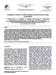
Figure 6: Reference network topology with α = 5 and d =2 Figure 7 shows the memory occupation versus the number of flows. We notice a trade-off point when there are approximately 9 flows per ED.
Total amount of memory (bytes)
Number of flows
1≤k≤d-1
Q ⋅ α G −� � ⋅ Q ⋅ 1(' ⋅ (� 1(' − α G −� − α G − � ) ≅ 1(' − � 1�
To give some numeric results, we use the previous formulas in a reference network topology with depth G � and α 11 5. We assume the following data size for the information to be stored: − >)6,@: for IP version 4 unicast flows with guaranteed services FSI is composed by the following field: - Session: 8 bytes (destination info); - Flow_spec: 44 bytes (Reservation information); - Filter_spec: 8 bytes (source info);
Figure 7: Example of memory occupation of the reference network topology with α=5 and DL=3 It is interesting to compare the global memory occupation for a single flow. In Figure 8 we notice that while for RSVP this value is constant, in ACS-RA these value decrease as long as the number of flow grows. This behavior is due to the sharing of ACS memory by all flows and it shows a better scalability of ACS-RA than RSVP when the number of flows for ED increases. 5.1.1.� Network bottlenecks Using the previous results, we compare network bottlenecks of both models. For this reason we selected backbone routers (for RSVP model) and ACS (for ACS-RA model) as network elements requiring the allocation of the biggest amount of memory. Let us consider the memory needed in a backbone router and in the ACS for the following target network topologies: (125 EDs) a) α = N1= 5 , d = 3 b) α = N1= 8 , d = 3 (512 EDs) c) α = N1= 10 , d = 3 (1000 EDs) When network size grows, the tradeoff point shifts versus a great number of flows for ED but however Figure 9 shows that, around to 500 flows for ED, RSVP backbone routers and
ACS need an amount of memory which have the same order of size. It is necessary remember that in RSVP case several backbone routers are required while in ACS-RA case only one management device (ACS) is needed. 1000
Toal amount of memory (bytes)
900 800 700 600 500 400
5693
300 200 100
$&6�5$
0
5
10
15
20
25
30
35
40
Number of flows for edge device
Figure 8: Memory occupation for single flow 7
2.5
x 10
7UDGHRII�OLQH
Total amount of memory (bytes)
2 $GPLVVLRQ�&RQWURO�6HUYHU��F
F �� U WH X R �U H U R �F 3 9 6 5
1.5
E U�� WH RX H�U RU 3�F 69 5
1
$GP LVVLRQ�&RQWURO�6HUYHU��E
0.5 �FRUH 5693
U��D �URXWH
$GP LVVLRQ�&RQWURO�6HUYHU��D
0
0
200
400
600
800
1000 1200 1400 1600
1800 2000
Number of flows for edge device
Figure 9: Comparison of ACS-RA and RSVP bottleneck elements 5.2.� Work load in RSVP and ACS-RA models In this paragraph we keep on the RSVP and ACS-RA comparison taking into account the total amount of work that they have to perform during the set-up, maintaining and teardown of flows. The total amount of control load and a persystem load are analyzed. The aim of the following analysis is simply to give an idea of the work load comparing the two strategies; a precise analysis of the load within each router or ACS-RA device is out of the scope of this paper and requires more sophisticated models. For this reason a simple approach will be followed. Every control message exchanged between routers or between EDs and ACS is considered. The control process load will be evaluated taking into account the work needed to execute the main operations related to the handling of each control message. We will refer as [PHVVDJH�[] as the total amount of work units needed to perform all operations related to the reception of “message-x”� Table 1 shows a list of main control messages for each network element in both architectures.
Message New PATH message [new PATH] Refreshing PATH message [ref PATH] New RESV message [new RESV] Refreshing RESV message [ref RESV] Tear down [Tdown] Admission Request [Admission Req] Release Request [Release Req]
RSVP Router X X X X X
ACS-RA ED ACS X X X X X X X
Table 1: Control messages Moreover, we indicate with 1UHI the number of PATH and RESV refresh messages during a single flow session. Let us consider the total amount of network systems work for the set-up, maintaining and tear-down of each flow session; for RSVP and ACS-RA architectures: − RSVP: PL.Nref.([UHI3$7+]+[UHI5(69])+PL.([QHZ3$7+]+ +[QHZ5(69] +[7GRZQ]) − ACS-RA: 2Nref.([UHI3$7+]+[UHI5(69])+2([QHZ3$7+]+[QHZ5(69]+ +[7GRZQ]) + [$GPLVVLRQ 5HT] + [5HOHDVH5HT] By substituting one work unit for each message we obtain the total number of messages handled for each flow. Although the simple counting of control messages is a rude way to compare the two architectures, it can be the starting point of the analysis of the amount of processing load. A more “sophisticated” analysis can be done trying to assign specific load values to the processing of each message (in terms of work unit). In the following analysis we use load weights reported in Table 2. As Table 2 shows, we fixed as work unit the work required by refresh messages, whereas the work required by new reservation messages was set as . times a work unit. The aim is to investigate work load varying the . parameter. Event [new PATH] [ref PATH] [new RESV] [ref RESV] [Tdown] [Admission Req] [Release Req]
RSVP router 2 1 K 1 2
ACS-RA ED ACS 2 1 K/2 1 1 2/3 K 1
Table 2: Work loads (in work units) per received message We want to remark that these are merely “magic numbers” just to give a better feeling of the overall load needed in network systems. This analysis leads to the following results: − RSVP: 2.PL.Nref + (K+4).PL − ACS-RA: 4.Nref + 13/6 K +8 Note that the overall work load grows when the number of crossed routes increases in a RSVP architecture, whereas it is not topology depended in a ACS-RA. Although the total amount of work needed to handle a single flow can be useful to understand the complexity of the two architectures, an other useful parameter is the work load per time unit required by each flow for each network element. Let us now focus on the work load per time unit required by
6.� Conclusions A framework for the interworking of RSVP with a differentiated services network has been described. We assumed that the implementations of diff-serv model will start supporting “static” Service Level Agreements. The step towards RSVP based services and the corresponding mapping of RSVP flows into diff-serv SLAs basically requires that the resource allocation approach moves from a static towards a dynamic one. A dynamic mechanism called ACS-RA (Admission Control Server based Resource Allocation) has
been proposed. The important point is that the user plane level will not substantially change, only a more intelligent management of resources can provide a high level of service assurance with no loss on network efficiency. This is a very important indication as it enables to build core routers with fast forwarding functionality based only on diff-serv information. The resource allocation functionality is then superimposed as an overlay. The scalability issues related to the ACS-RA have been analyzed in comparison with RSVP. As far as the user plane is concerned the ACS-RA behaves far better than a RSVP based network, as it inherits the advantages of the diff-serv approach. Therefore we focused our analysis on the control plane scalability. The amount of memory and the processing load in the network elements have been considered for comparison. We found that the scalability properties of ACSRA are satisfactory. Our results show that even in the case of a single Admission Control Server in a diff-serv cloud, the ACS-RA scales better than RSVP. 100 90
Nref (nuber of “refresh” RESVper session)
each flow for each network element. We indicate with: − refR: the refreshing rate; i.e. the number of refresh message per time unit; − sesR: the session rate; i.e. the number of tear-down messages per time unit that is the inverse of the mean duration of a session flow. Let us consider a single RSVP router and the ACS; the number of work units per time unit are, respectively: − RSVP router: refR.([UHI3$7+]+[UHI5(69]) + sesR.([QHZ3$7+] + + [QHZ5(69] + [7GRZQ]) = = 2.refR + (K+4).sesR − ACS: sesR.([$GPLVVLRQ 5HT] + [5HOHDVH 5HT]) = = (2/3 K+1).SesR Multiplying these values by the number flow that a single system has to handle in the same time we obtain the global work load per network element. In the RSVP architecture, focusing on backbone routers (first level routers), the number of flows per router is: 2.n.NED. . − RSVP core router: [2 refR + (K+4).sesR] N1 In a ACS-RA architecture the ACS has to handle all active flows; this means that the total amount of work load is: − ACS: n.NED.sesR.([$GPLVVLRQ 5HT]+[5HOHDVH 5HT]) = = (2/3 K+1).n.NED.sesR There is a trade-off between the two architectures depending on the number of refresh messages per session and the number of core routers: ACS − : RSVP router N1.(2/3 K+1) (2/3 K+1).N1.sesR = . . . . . 2 [2 refR + (K+4) sesR] 2 (2 Nref+K+4) Anyway it has to be remarked that for ACS-RA there is only one device with that amount of work whereas in RSVP environment all core routers (11) are loaded with that value of work. Figure 10 shows trade-off lines between RSVP routers and ACS in terms of work load. The three lines refer to a ratio of 3:2, 1:1 and 2:3 between ACS load and router load, varying the . parameter and the number of refresh messages per session. The picture shows that also for big values of N as soon as the number of refresh messages increases the work load for ACS is less than the work load for each backbone router in a RSVP architecture.
80 � G D R �O U WH X R �U UH R �F 3 9 6 5
70 60
G D OR U� H UY H �6 & �$ �� ��
50 40
G� RD U�O WH RX H�U RU 3�F 9 56
30
G RD U�O YH HU &�6 �$
20 � �ORDG RXWHU �FRUH�U 5693
10 0
0
10
20
30
40
50
60
70
HU�ORDG &�6HUY �����$
80
90
100
K = [new resv]/[refresh resv]
Figure 10: ACS / RSVP work load trade-off
7.� References [1] P.White, “RSVP and Integrated Services in the Internet: A Tutorial”, IEEE Communications Magazine, May 1997 [2] D. Black et al. “An Architecture for Differentiated Services”, Internet-draft, Diffserv working group, May 1998, [3] Y.Bernet et al. “A Framework for Differentiated Services”, Internet-draft, Diffserv working group, May 1998, [4] Y.Bernet et al. “A Framework for Use of RSVP with diff-serv Networks”, Internet-draft, June 1988, [5] I.Stoica, H.Zhang “LIRA: An Approach for Service Differentiation in the Internet”, NOSSDAV ’98, 8-10 July, 1998, Cambridge, UK. [6] K. Nichols, V. Jacobson and L. Zhang “A Two-bit Differentiated Services Architecture for the Internet” Internet Draft, November 1997 [7] C.Huitema “Routing in the Internet”, Prentice Hall, 1995 [8] G. Malkin, “Traceroute Using an IP Option”, RFC 1393