Sep 12, 2011 - structure of the compound suggests that the (100) surface is formed by ... surfaces of some complex metallic compounds, e.g., Al13Co4,.
PHYSICAL REVIEW B 84, 115410 (2011)
Surface structures of complex intermetallic compounds: An ab initio DFT study for the (100) surface of o-Al13 Co4 M. Krajˇc´ı1 and J. Hafner2 1
Institute of Physics, Slovak Academy of Sciences, D´ubravsk´a cesta 9, SK-84511 Bratislava, Slovak Republic 2 Fakult¨at f¨ur Physik and Center for Computational Materials Science, Universit¨at Wien, Sensengasse 8/12, A-1090 Wien, Austria (Received 21 June 2011; published 12 September 2011) The formation and the structural and electronic properties of the (100) surface of the complex intermetallic compound Al13 Co4 have been investigated using ab initio density functional methods. While the layered crystal structure of the compound suggests that the (100) surface is formed by cleaving the crystal between adjacent flat (F ) and puckered (P ) layers, a simulated cleavage experiment shows that the P layer splits into two complementary parts to preserve the integrity of very stable clusters forming pentagonal bipyramids (PB’s). The stable surface is terminated by an incomplete P layer consisting of the tips of the PB clusters and exposing in the interstices that part of the underlying F layer forming the connection between the PB’s. The stability of this strongly corrugated surface is further confirmed by the calculation of the surface energies and of the formation energies of surface vacancies, as well as by a simulated high-temperature annealing. The analysis of the electronic structure shows that the stability of the PB clusters arises primarily from strong, partially covalent vertical Co-Al-Co bonds between the tips of the clusters. Simulated scanning tunneling microscopy (STM) images are provided to permit a comparison with the STM experiments of Addou et al. [Phys. Rev. B 80, 014203 (2009)]. Measured and simulated STM images are in good agreement, possible reasons for the remaining differences in the Al/Co contrast are discussed in detail. DOI: 10.1103/PhysRevB.84.115410
PACS number(s): 68.35.bd, 68.37.Ef, 73.20.At
I. INTRODUCTION
While the low-index surfaces of pure metals have been studied for decades and are today well understood,1 the surfaces of complex intermetallic compounds still represent an unexplored area. Surfaces of complex intermetallic compounds attracted attention particularly because of their unusual chemical reactivity and possible catalytic properties. While the surfaces of close-packed metals have only a few inequivalent adsorption sites, the surfaces of complex intermetallics provide a rich variety of different adsorption sites, leading to a multitude of possible reaction channels for catalytic reactions. For instance, it was discovered recently by Armbr¨uster et al.2 that surfaces of some complex metallic compounds, e.g., Al13 Co4 , can be highly active and selective catalysts for acetylene hydrogenation. Acetylene hydrogenation is an important step in the industrial production of the polyethylene. Usually Pd is used as catalyst, and the possibility to replace expensive Pd by a cheaper Al-based transition-metal alloy is highly intriguing. The determination of the atomistic structure of the surface of a complex intermetallic compound is a difficult and challenging task. A standard method for surface investigations is scanning tunneling microscopy (STM). Complex intermetallic compounds generally exhibit rather irregular, often corrugated surfaces. Atomically flat surfaces suitable for STM studies are formed only for compounds with a layered structure consisting of dense atomic layers. STM images with atomic resolution can be achieved only for specific crystallographic directions. At a lower resolution STM studies reveal a sequence of smaller or larger flat terraces with step heights corresponding to the distance between the preferred cleavage planes. High-resolution STM images of individual terraces provide important information about the structure of the surface at the subnanometer scale. However, from the STM images alone is very difficult to identify the observed terraces 1098-0121/2011/84(11)/115410(14)
with possible cleavage planes. To predict which atomic planes appear at the surface has been proved to be quite difficult. For the understanding the atomic surface structure it is very helpful to compare experimental STM images with simulated STM images calculated using ab initio density functional theory (DFT) methods for tentative structural models of the surface. Since the early 1990s, significant progress has been made in the preparation and characterization of surfaces of complex metallic compounds. Quasicrystals can be considered a special class of complex metallic compounds with a very high structural complexity. Surfaces of stable Al-TM (transition metal) quasicrystals like the 5-fold surface of icosahedral Al-Pd-Mn or the 10-fold surface of decagonal Al-Co-Ni have been studied most intensively.3–8 It is remarkable that despite their complex aperiodic atomic structure the surfaces of some Al-TM quasicrystals can be atomically flat. Surfaces of Al-TM quasicrystals exhibit high hardness, good tribological properties such as low surface friction, and high oxidation resistance, i.e., properties important for technological applications. Surfaces of quasicrystals and their crystalline approximants have also unusual chemical reactivity and can be used as templates for molecular adsorption.9 Recently Deniozou et al.10 investigated the structure of the (010) surface of orthorhombic complex metallic alloy T-Al3 (Mn, Pd) using low-energy electron diffraction, x-ray and ultraviolet photoemission spectroscopy, and STM. This compound with 156 atoms per unit cell is considered to be an approximant to the decagonal Al-Mn-Pd quasicrystal. The structure can be seen as a sequence of dense atomic layers along the pseudodecagonal axis: flat (F ) and two kinds of puckered layers (P 1 and P 2). It was shown that the surface with a step-terrace morphology is formed predominantly by the puckered P 2 layers. Because of structural imperfections a comparison of measured and
115410-1
©2011 American Physical Society
ˇ ´I AND J. HAFNER M. KRAJC
PHYSICAL REVIEW B 84, 115410 (2011)
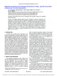
simulated STM images was possible only on a qualitative level. The (110) surface of γ Al4 Cu9 was investigated by Gaudry et al.11 using STM and ab initio DFT methods. The STM studies show that surfaces prepared at elevated temperatures above 843 K exhibit a step-terrace morphology with two kinds of terraces denoted as L and S. The structure of γ Al4 Cu9 (cP52) can be seen as a 3 × 3 × 3 CsCl superstructure with two vacancies. Along the (110) direction flat F and puckered P atomic layers alternate in a FPPFPPF. . . stacking sequence. The comparison of measured and simulated STM images shows that of three possible terminations F , PF (P layer above F ), and PP (P above other P ) the S terrace corresponds to the PP terminationand the L terrace to the PF termination and F does not appear at the surface. The (100) surface of orthorhombic Al13 Co4 (cP102), an approximant to the decagonal Al-Co-Ni quasicrystal, has been studied by Addou et al.12 Surfaces were prepared in ultrahigh vacuum by sputtering (Ar+ , 1.5keV) and anneal cycles at temperatures between 1073 K and 1173 K. STM measurements performed at room temperature show the presence of two different types of surface terminations, T1 and T2. Similarly as for γ Al4 Cu9 , the structure of Al13 Co4 can be considered as a FPPFPPF. . . stacking of two flat and puckered layers along the (100) direction. However, it turned out that the observed surface terminations do not agree with any of the bulk layers. After considering several models of the surface structure it was concluded that a substantial part of the atoms are desorbed. The observed T1 and T2 terraces correspond either to an incomplete puckered (iP ) or to an incomplete flat layer, respectively. In the iP surface layer approximately one half of the 26 atoms of the P layer per surface unit cell is missing. High-resolution STM images of the T1 terminations exhibit a regular pattern resembling the texture of a piece of fabric; see Fig. 1(a) (reproduced with permission from Fig. 3(a) in Ref. 12). STM images of the T2 termination show structural disorder; see Fig. 3(c) in Ref. 12. While the regular texture of the T1 surface is preserved up to 1173 K, the T2 termination is gradually desorbed at elevated temperature. Above 1173 K the
FIG. 1. (Color online) (a) 20 × 20 nm2 high-resolution STM image presenting two successive terraces separated by a single-step height equal to a/2. The elongated hexagons (longest edge equal ˚ are rotated from one puckered layer to the next by 80◦ . to 19 A) (b) Atomically resolved STM image (10 × 10 nm2 ) recorded from T1. Bipentagonal motifs are highlighted on the image [(Inset) FFT calculated from T1 termination shown on (b).] Reproduced with permission from Ref. 12.
majority of the surface consists of T1 terraces corresponding to the incomplete P layer. The comparison of experimental STM images with those calculated for several tentative structural models of the surface is more problematic for complex intermetallic compounds than for closely packed structure of pure metals. Possible reasons for the unsatisfactory agreement of simulated and experimental STM images of the complex metallic surfaces are discussed in Sec. VII. In this work we study the (100) surface of orthorhombic Al13 Co4 using ab initio DFT methods. For the determination of the surface structure a simulation of the cleavage process and its interpretation in terms of the chemical bonding proved to be very helpful. A calculation of the surface energy is straightforward only if the slab used to represent the surface has the same stoichiometry as the bulk, which is generally not the case for surfaces of complex intermetallics. Nevertheless, in Sec. V A we show that the calculated surface energies provide information about the preferential cleavage planes. The calculation of the formation energies of surface vacancies characterizes the binding of individual surface atoms to the substrate; see Sec. V. The thermodynamic stability of the surface can be tested by high-temperature annealing using ab initio molecular dynamics; see Sec. V C. Our theoretical results agree well with the experimental work of Addou et al.12 The simulated cleavage shows that the (100) surface of Al13 Co4 consists of incomplete puckered layers; one half of the puckered layer exposed at the surface is missing. However, we demonstrate that it is the other half of the plane that is missing than that suggested by Addou et al.12 We assume that we have collected enough arguments to support this conclusion. II. COMPUTATIONAL METHODS
Electronic structure calculations have been performed using the Vienna ab initio simulation package (VASP).13,14 VASP produces an iterative solution of the Kohn-Sham equations of DFT within a plane-wave basis. We used the semilocal exchange-correlation functional in the generalized gradient approximation (GGA) proposed by Perdew et al.15 VASP allows us to calculate the Hellmann-Feynman forces acting on atoms. The equilibrium positions of the atoms during the simulated cleavage process and the surface geometry have been determined by a conjugate gradient minimization of the forces acting on the atoms. Details of the cleavage process are presented in Sec. IV. The large dimensions of the computational cell allowed us to perform many of calculations in the � point only. In the simulated cleavage experiment we have used a model consisting of two unit cells (204 atoms in the computational cell). The surfaces of different terminations are represented by slabs cut from the bulk structure. The thickness of the slab should be large enough to stabilize the surface. Our models of the studied terminations consist of seven atomic layers per computational cell forming a symmetric slab with ˚ plus a vacuum layer of 12 A. ˚ The energies the thickness of 14 A were calculated in the basis set contained plane waves with a kinetic energy up to Ecutoff = 600 eV. For the calculation of the surface energy in Sec. V A we used a slab model with eight atomic layers and a k point mesh with 4 × 3 × 1 points.
115410-2
SURFACE STRUCTURES OF COMPLEX INTERMETALLIC . . . III. CRYSTAL STRUCTURE OF O-AL13 CO4
The structure of orthorhombic Al13 Co4 has been determined by Grin et al.16 using x-ray single-crystal and powder diffraction methods. The structure and the stability of oAl13 Co4 and related phases has been studied recently by Mihalkoviˇc and Widom17 using DFT. The orthorhombic unit cell contains 102 atoms (Pearson symbol oP102, space group P mn21 , No. 31), and of them 78 are Al and 24 Co atoms. The ˚ lattice parameters reported by Grin et al.16 are a = 8.158 A, ˚ and c = 14.452 A. ˚ The structure of Al13 Co4 b = 12.342 A, can be considered as a stacking of alternating flat (F ) and puckered (P ) layers along the (100) direction at distances of ˚ A side view on the unit cell and the stacking a/4 = 2.04 A. sequence of the F and P layers is presented in Fig. 2(a). The unit cell consists of two F and two P layers in the sequence F0.00 P0.25 F0.50 P0.75 . The puckered planes P above and below the F plane have exact mirror symmetry with respect to this plane, e.g., P0.25 and P0.75 are mirrored against the plane F0.50 . The Al13 Co4 structure can be considered to be an approximant to the decagonal Al-Co-Ni quasicrystal. The periodic axis of the quasicrystal coincides with the stacking direction [100]. The structure of the atomic layers shows various motifs with pentagonal symmetry. The arrangement of atoms in the (100) planes can be described by a planar tiling consisting of pentagons with two opposite orientations and thin rhombi. ˚ Per unit cell there are The edge of the tiling is dP = 4.73 A. (a)
P F P F (b)
FIG. 2. (a) A side view of the layered structure of Al13 Co4 . The unit cell consists of alternating flat F and puckered P layers. Positions of atoms are shown by circles as follows: Al, open circles; Co, soled circles. The gray circles mark Al sites with a fractional occupancy. Alternatively, the structure can be seen as a packing of four pentagonal bipyramid (PB) clusters. One such cluster is marked by dashed lines. (b) A side view of the structure of PB cluster with idealized coordinates of atoms. It consists of an equatorial plane and two Al pentagons centered by Co atoms. The Co atoms centering ˚ above or below the Al the Al pentagonal rings are slightly (0.45 A) pentagons and form the tips of the BP. In the equatorial plane the BP has a decagonal ring of alternating Al and Co atoms and one Al atom in the center of the ring; see also Fig. 3. For greater clarity Al atoms are here shown by bigger circles.
PHYSICAL REVIEW B 84, 115410 (2011)
four pentagons and two rhombi. Alternatively, the structure can be described by a tiling of with squashed hexagons (H ) ˚ The vertices of the with an edge measuring dH = 6.51 A. H tiling coincide with the centers of the pentagons. The H tiling is helpful for the understanding of the relation between the orthorhombic Al13 Co4 and other structures. In orthorhombic Al13 Co4 the H tiles form a zigzag pattern, while in monoclinic Al13 Co4 all tiles are parallel. In the Co-rich Al-Co-Ni quasicrystal the H tiles are part of a more general decagon-hexagon-boat-star (DHBS) tiling describing the quasiperiodic ordering. Figure 3 shows the atomic structure of the P and F layers, respectively. In a single P layer the interior of each pentagonal tile is decorated by a Al pentagon centered by a Co atom. Thin rhombi are centered by one Al atom. While the vertical positions of the Al atoms in the thin rhombi are very close to the ideal plane with x = 0.25, positions of the atoms decorating the pentagonal tiles are shifted in the vertical direction (along [100]). In one half of the pentagonal tiles the central Co ˚ above the x = 0.25 plane [in atoms are shifted by +0.22 A Fig. 3(a) they have positive “parity”] and, simultaneously, the ˚ surrounding Al atoms are shifted (in average) by −0.23 A below this plane. In the other half of the pentagonal tiles the shift the atoms is in the opposite direction [in Fig. 3(a) they are marked by negative “parity”]. Around each pentagonal tile there are three other adjacent edge-sharing pentagons. Two of them have an opposite “parity,” and one has the same “parity.” Pentagons with the same “parity” thus occur in pairs. In the P layer the vertices of the pentagonal tiling are unoccupied. In the F layer all vertices are occupied with Co atoms. Thin rhombi are occupied by two Al atoms located along the long diagonal. The interior of the pentagonal tiles can be decorated either by one or three Al atoms. Aluminum atoms occupy also all midedge positions, unless the edge is shared with a rhombic tile. In the relaxed structure two of the midedge Al atoms of a pentagon with three internal Al atoms are shifted inward such that this tile contains five atoms. This contrasts with the packing of the other pentagon decorated by only one internal Al atom only. The central position of this one Al atom inside the pentagonal tile is very remarkable. Considering only geometrical constraints inside a pentagonal tile there is a space for accommodating at least three Al atoms. Around the central Al atom there is thus plenty of free space. In next Sec. IV it will be shown that this lose atomic packing is stabilized by strong vertical Co-Al-Co bonds with enhanced covalency. These bonds are also very essential for understanding that the cleavage process leads to a splitting of the P layer, see Sec. IV. Per unit cell a P layer contains 22 Al atoms and 4 Co atoms and an F layer 17 Al and 8 Co atoms. The P has thus a slightly higher atomic density than the F layer. While according to the work of Grin et al.16 all 102 sites of the unit cell have full occupancy, Mihalkoviˇc and Widom17 have shown that a fractional occupancy of ≈0.5 of the Al sites inside the thin rhombi in the P layers increases the thermodynamic stability of the Al13 Co4 compound. An alternative description of the structure of Al13 Co4 is based on the packing of atomic clusters forming pentagonal bipyramids (PB).18 A PB cluster consists of a decagonal ring of Co and Al (centered by Al) in the equatorial plane and two
115410-3
ˇ ´I AND J. HAFNER M. KRAJC
PHYSICAL REVIEW B 84, 115410 (2011)
(a)
(b)
+
+
CC’
+
+
+
+
CC’
+
+
FIG. 3. (Color online) Atomic structure of the puckered P (a) and flat F (b) layers shown in 2 × 2 unit cells. Aluminum atoms are represented by light blue (darker) or yellow (lighter) circles, and positions of Co atoms are shown by magenta (dark) circles. The arrangement of atoms in the planes can be described by a planar tiling consisting of pentagons and thin rhombi (full red lines). Alternatively it can be described also by a tiling of squashed hexagons (dashed blue lines). In(a) the clusters of five Al atoms centered by Co form top (light blue) or bottom (light yellow) parts of the PB clusters. In (b) the pentagon marked by light gray background shows the loosely packed interior of the PB cluster. The pentagon with green (darker) background marks one of the other constituent unit of the crystal structure: the junction pentagon connecting the equatorial planes of neighboring PB’s. Arrows CC � indicate the position of the plane intersecting the unit cell used to show the charge density distribution in Figs. 4 to 6.
˚ above and below; Al pentagons centered by Co atoms 0.45 A see Figs. 2(b) and 3. In Al13 Co4 the equatorial plane of each BP is part of the F layer and the Al pentagons with the Co tips belong to two P layers above and below. In the [100] direction the PB clusters alternate with flat junction layers (five Co atoms in vertices of a pentagon filled by five Al atoms) to form a “PB column” (PBC)17 ; see Fig. 4(a). Per unit cell there are four PB clusters, linked together in pairs: In the equatorial flat planes they share two Co atoms and one Al atom. In the [100] direction one pair of linked PB clusters is shifted with respect to the other pair by a/2. We note that the PB cluster occurs also in other related compounds and in Co-rich A-Co-Ni decagonal quasicrystal. Interatomic bonding within the PB cluster is remarkably strong. This is seen also form the extraordinarily short distance between the central Al atom and the two Co atoms at the tips ˚ in the bulk). In Fig. 4(a) the positions of two of the BP (2.29 A PB clusters are shown by dashed lines, the Co-Al-Co bonds between their tips are marked by red stripes. Figure 4(b) shows the charge distribution in the plane z = c/2 (marked by CC� in Fig. 3). The top part of the figure presents the total valence electron distribution, the bottom part the positive values of the difference electron distribution (i.e., the electron density after the valence electron densities of the free atoms have been subtracted). The difference electron density distribution illustrates the accumulation of electrons along the bonds between the central Al and the Co atoms in the tips of the PB clusters and characterizes the partially covalent character of the Al-Co bonding. Recent nuclear magnetic resonance (NMR) studies19,20 have identified two 27 Al signals; one has been attributed to Al atoms in the outer shell of the PB’s, and the second correlates with an exceptionally large axially symmetric quadrupole splitting to Al atoms in the center of
the PB’s. The large splitting arises from the strong Co-Al-Co bonds between the tips of the PB’s. IV. SIMULATED CLEAVAGE AND CHEMICAL BONDING IN AL13 CO4
Because of the layered crystal structure of one could expect that a (100) surface of Al13 Co4 is formed by cleavage between the F and P layers. However, quite surprising, it turns out that on cleavage the P layer is split into two complementary parts and the surface consists of an incomplete P layer with parts of the underlying F layer exposed in the interstices. In this section we demonstrate that this is a consequence of the strong chemical bonding between Al and Co atoms in the PB clusters. In Al-TM compounds one frequently observes chemical bonds with enhanced covalency.21 The partially covalent Co-Al-Co bonds between the tips of PB and the central Al atom are not exceptional and it is also correct to say that the bonds are strong but not exceptionally strong. In some Al-TM compounds, e.g., Al2 Ru21 or some quasicrystalline approximants, e.g., Al-Pd-Re6,22 the covalent Al-TM bonds are so strong that the bonding-antibonding splitting creates a semiconducting gap in the electronic spectrum. In the electronic spectrum of Al13 Co4 (see Sec. VI), only a deep pseudogap is found. The character of the bonding also influences the response to a tensile deformation of the crystal.23–25 We have simulated the cleavage process of Al13 Co4 by an increasing tensile deformation of the crystal along the [100] direction. The computational cell was extended in the [100] direction first by a/2 the forces were relaxed and then extended again by a/2. The tensile deformation induces a splitting of the P layers. Each column of PB’s splits into the PB clusters
115410-4
SURFACE STRUCTURES OF COMPLEX INTERMETALLIC . . .
PHYSICAL REVIEW B 84, 115410 (2011)
F
(a)
(b)
P F P F P F P F FIG. 4. (Color online) The models used for the simulated cleavage of Al13 Co4 consisting of two unit cells stacked in the [100] direction. (a) A side view of the computational cell: Al, open circles; Co, closed circles. The gray circles mark Al sites with a fractional occupancy. Two PB clusters are marked explicitly by dashed lines. The PB’s are stabilized by strong, partially covalent Co-Al-Co bonds between the tips of PB and the central Al atom marked by vertical red stripes. In the [100] direction the PB clusters alternate with junction pentagons (marked by green horizontal strips) to form a “PB column.” (b) Electron density distribution in the plane z = c/2, marked CC � in Fig. 3, demonstrating the partially covalent character of the Co-Al-Co bonds linking the PB tips. The top part is shows the total valence electron distribution, the bottom part the difference electron density, cf. text.
separated by the junction pentagons; see Fig. 5. Because of the periodicity of the structure and the mirror symmetry with respect to the F planes, four vacuum layers begin to form. The mirror symmetry can be broken by a small shift of the atoms in one layer or in a more realistic scenario by removing some Al atoms from the sites with fractional occupancy. One such removed atom is marked by a blue circle. Due to the broken mirror symmetry the four layers with reduced electron density are no longer equivalent. At further increased tensile strain cleavage takes place in the P layer with broken symmetry. Figures 4 to 6 demonstrate the simulated cleavage process. Figure 4 shows the initial configuration of atoms in the computational cell. The structure in Fig. 5 is an intermediate state obtained during the simulation after expansion of the computational cell by a/2 in the [100] direction and relaxation of interatomic forces. In Fig. 6 formation of one vacuum layer after breaking the mirror symmetry is shown. Also here the atoms are in their equilibrium positions. The computational cell with the final configuration of atoms obtained after another elongation of the cell by a/2 is not shown as it essentially differs from that in Fig. 6 only by a larger width of the vacuum layer. The Co-Al-Co bonds in the PB clusters are marked by red color, and the junction layers (pentagons) are marked by green color. Cleavage creates two surfaces separated by a vacuum layer. The bottom surface is formed by the upper parts of the PB clusters in the P layer and the junction pentagons in the F layer. The formation of the incomplete P layer at the surface is thus a consequence of the existence of the strongly bonded PB clusters and the shift of one pair of PB clusters with
respect to the other by a/2. We have denoted the incomplete P layer by iP and its complement by iP � . The surface consists of two parts: the incomplete P layer (iP ) and the exposed ˚ deeper. Together part of the lower F layer (eF ) lying 2 A they form a highly corrugated surface denoted by the label Z. The corrugation of the Z surface is well seen in the charge density profile of the surface presented Fig. 6. In Fig. 7(a) the corrugation is obvious from the existence of wide valleys in the lateral charge density distribution. The peculiar shape of the Z surface is schematically shown also in Fig. 8(b). A structure of many complex metallic compounds can be described in terms of atomic clusters. The Al13 Co4 compound is one of few cases where the atomic clusters have some internal integrity, such that the surface follows the outer boundary of these clusters. In other compounds the surfaces are atomically flat, e.g., the fivefold surface of icosahedral quasicrystals, and the surface planes intersect the clusters.6 We also note that in the case of (100) surface of Al13 Co4 the simulated cleavage process leads to clean separation of complementary surfaces. In other compounds the simulated cleavage need not result in such clean separation of the surfaces. Very often formation of chains of atoms connecting the opposite complementary surfaces are observed. In such cases the simulated cleavage does not lead to well defined surfaces. Figure 7(a) shows the electron density in the iP plane, marked by SS � in Fig. 6(a). One recognizes Co atoms surrounded by Al pentagons; pairs of Co-centered Al pentagons are linked by thin rhombi decorated with a single Al atoms. These stripes are separated by wide troughs. At the place
115410-5
ˇ ´I AND J. HAFNER M. KRAJC
PHYSICAL REVIEW B 84, 115410 (2011)
(a)
(b)
P
F
P
F
P
F
P
F FIG. 5. (Color online) An intermediate state obtained during the cleavage simulation. (a) Positions of atoms in a computational cell extended in the [100] direction by a/2. The tensile deformation leads to the decomposition of the bulk structure into slabs of PB clusters (marked by vertical red stripes) separated by junction pentagons (horizontal green stripes). There are four PB’s per unit cell. Two PB’s in the plane CC � (z = 0.5c) are marked explicitly by dashed lines, the strong Co-Al-Co bonding between their tips is marked by dark red vertical strips, and Co-Al-Co bonds in other PB’s are marked by the light red color. One can observe that the puckered P layers spilt into two parts belonging to different slabs. (b) Electron density distribution in the CC � plane demonstrating that the Co-Al-Co bonding between the tips of PB’s preserves integrity of the PB clusters during the tensile deformation. Because of the mirror symmetry with respect to the four F layers, four layers with reduced electron density begin to form. The mirror symmetry can be broken by a small shift of atoms in one layer or in a more realistic scenario by removing some Al atoms from sites with fractional occupancy. One such removed atom is marked by blue circle. The symmetry breaking determines the position of the cleavage plane (dotted line and the arrow).
of the missing part of the P layer there are deep charge density valleys. As it was already mentioned before the Al site within a thin rhombus, in a bridge position between two Al pentagons is quite special. Mihalkoviˇc and Widom17 have shown that a fractional occupancy ≈0.5 of this site increases the thermodynamic stability of the Al13 Co4 compound. It is possible to assume that if this rather isolated atom appears at the surface it can easily desorb. This expectation is confirmed by our study presented in Sec. V B and experimentally by recently published STM images12 of the Al13 Co4 surface where in Fig. 1(b) (Fig. 3(b) in Ref. 12) it is clearly seen that after an annealing of the surface at high temperature (1173 K) most of these atoms desorb. Figure 7(b) shows the charge density in the part of the lower F layer which is partly exposed and partly buried below the iP layer, see the position of the F F � plane in Fig. 6(a). The largest part (two edge-linked pentagons per unit cell) of the exposed area of the F layer corresponds to the junction pentagons (distorted pentagons of Al atoms). The figure also shows sections through the equatorial plane of the PB clusters (the other two edge-linked pentagons with a single Al atom in their center). Ring-shaped areas of very low charge density
around the central Al atoms demonstrate why Al13 Co4 can be considered also as a cage compound.
V. ENERGETICS AND STABILITY OF POSSIBLE SURFACE TERMINATIONS A. Surface energies
Our simulated cleavage proceeds at zero temperature. One can expect that if the surface is prepared by cleavage at low temperatures the Z termination is preferred. At higher temperatures terraces with the terminations P or F could also appear if the differences in their surface energies is not too large. The surface energy can easily be calculated provided the stoichiometries of the slab used to represent the surface is the same as that of the bulk. A slab consisting of an even number of layers has bulk stoichiometry, and this also holds when the slab is split into two halves, whether cleavage takes places between F and P layer or whether one P layer is split into two complementary parts; see Fig. 8. The calculation yields, in the former case, the average surface energy of the P and F terminations and, in the latter case, the surface energy for the Z
115410-6
SURFACE STRUCTURES OF COMPLEX INTERMETALLIC . . . (a)
PHYSICAL REVIEW B 84, 115410 (2011) (b)
SS’ FF’
FIG. 6. (Color online) (a) Cleavage leads to the formation of two complementary surfaces separated by a vacuum layer. The surface is formed in such a way that the integrity of the PB clusters remain conserved. The profile of the charge density distribution (b) shows highly corrugated shape of the surfaces. Arrows SS � and F F � in (a) indicate horizontal sections through the computational cell used to show the electron density in Fig. 7.
terminations. For the calculation of the surface energy we used a slab model with eight atomic layers and a vacuum layer of ˚ For a slab split between the P and F layers we obtained 12 A.
a surface energy of σ (P + F ) = 1.24 Jm−2 . This value can be compared with the surface energy of fcc Al(111) for which we obtained σ (111) = 0.77 Jm−2 . [A similar value of 0.71 Jm−2
FIG. 7. (Color online) Electron density distribution in the surface, in the incomplete P layer (left panel, see plane SS � in Fig. 6) and in the underlying layer (right panel; see plane F F � in Fig. 6). The red lines show the pentagon-rhombus tiling and the dashed blue lines the hexagon tiling. The Al atoms inside the rhombi (one is marked by a blue circle) can easily desorb; cf. text. 115410-7
ˇ ´I AND J. HAFNER M. KRAJC
PHYSICAL REVIEW B 84, 115410 (2011)
(a)
(b)
FIG. 8. (Color online) In model (a) the surface is formed by P (red, thicker) and F (blue) atomic layers; model (b) has two Z surfaces consisting of incomplete P layers and exposing parts of the underlying F layers.
was obtained also recently by other authors.26 We note that the frequently reported27 larger value of 1.27 Jm−2 for the surface energy of fcc Al(111) was calculated by the LMTO method for an unrelaxed surface.] The slab with two opposite Z terminations has exactly the same stoichiometry as the bulk. The surface energy for the Z termination is σ (Z) = 1.19 Jm−2 ; this is remarkably low. The formation of two opposite surfaces with Z termination is thus by 0.1 Jm−2 energetically more favorable than the formation of surfaces with a P termination on one and an F termination on the other side of the cleavage plane. It is possible that the surface energy for either P or F termination is lower than for the Z termination. However, the formation of this surface by a cleavage process is hindered by the higher surface energy of the complementary surface. A surface with F termination could be formed by the desorption of the iP part of the as cleaved surface, a surface with Z termination could be formed from a P surface by desorption of part of the top layer. B. Desorption energies
In Sec. IV we have shown that formation of the corrugated Z surface is the preferred termination at low temperatures when the Al13 Co4 crystal is cleaved in the [100] direction. As the surfaces for STM measurements are prepared by repeated annealing at high temperatures (up to 1173 K) it might be possible that experimentally observed surfaces differ from the low-temperature surfaces. As already mentioned in the Introduction, Addou et al.12 observed that from the layers exposed at the surface a substantial part of atoms are desorbed. To shed light on this important topic we investigated the energetics of the desorption of a single atom from all possible surface terminations. The energy Ev required for the formation of a surface vacancy is calculated as a difference of the total energy of the stoichiometric slab with N atoms and the total energy of the slab containing a vacant site plus the chemical potential of the atom removed from the slab. Ev (J ) = Etot (N − 1,J ) − Etot (N ) + μJ
where J stands for a vacant Al or Co site and μJ stands for the chemical potential of the corresponding atomic species. Etot (N − 1,J ) and Etot (N ) are the energies of the surface models with and without the vacancy J , respectively. The admissible range of the chemical potentials is determined by the condition of thermal equilibrium between the Al and Co reservoirs and the bulk Al13 Co4 crystal and that the crystal must be stable with respect to the formation of compact Al or Co islands on its surface. Stability with respect to the formation of Al or Co islands on the surface requires that the chemical potential must be lower that the energy of the energy of the species in its stable metallic phase. For both Al and Co vacancies, the maximum allowable value of the chemical potential has been chosen; this corresponds to the desorption energy from a surface in equilibrium with bulk fcc Al or bulk hcp Co, respectively, μAl = Eatom (Al:fcc), μCo = Eatom (Co:hcp). The binding energies of Al and Co atoms in the elemental metals are Eatom (Al:fcc) = −3.70 eV, Eatom (Co:hcp) = −6.81 eV. The structure has been relaxed after the creation of the vacancy until all forces acting on the atoms are converged to zero. At some sites the vacancy was filled by neighboring atoms moving into the vacant site. The results for all three surface terminations are presented in Table I. Figure 9 presents a top view of the P , F , and Z surfaces. The (ideal) position of atoms in the surface planes are related through their point group symmetries. On the P surface one can distinguish 12 inequivalent sites for Al atoms and 2 for Co atoms, on the F surface there are 9 inequivalent sites for Al, and there are 4 for Co. At the maximum value of the chemical potential for Co, the energies for the formation of a Co surface vacancy are about 1.5 eV on both the F and P surfaces; on the Z forces they are slightly lower with about 1.3 eV. Energies for the formation of an Al vacancy scatter more widely. At the P TABLE I. Vacancy formation energies Ev in (eV) for surface atoms in the P , F , and Z terminations; see also Fig. 9. Missing numbers means that a vacancy could not be created at this site. The + indicates that the removed atom is replaced by an atom from the subsurface F layer. In the case of the Z termination the exposed part of the F surface is slightly overpacked. If one of the atoms at the sites marked by the—sign is removed the remaining atoms rearrange to the same less packed configuration, cf. text. P termination A1 A2 A3 A4 A5 B1 B2 B3 B4 B5 A6 B6 C1 C2
(1) 115410-8
1.64 + 1.53 1.61 1.53 0.26 0.26 0.83 0.67 0.70 1.14 0.75 1.47 1.55
F termination A1 A2 A3 A4 A5 A6 A7 A8 A9 A9a C1 C2 C3 C4
1.54 2.10 1.14 1.54 1.68 1.07 1.92 1.54 0.02 0.50 1.54 1.27 1.49 1.53
Z termination A1 A2 A3 A4 A5 A6 A7 A8 A9 A10 A11 A12 C1
1.64 1.72 1.52 + 1.47 0.42 – 1.09 – – – 1.09 1.27
SURFACE STRUCTURES OF COMPLEX INTERMETALLIC . . .
PHYSICAL REVIEW B 84, 115410 (2011) C1
A5 A2
A1
A1
C2 B2
B5 B1
A6 B5
C2
C3
B5 C2
A1
B4
B3
C1 A3
B6
B4
B3
A9
A1
A3
A10 A8
A1
C4
A4
A8
C1
A14
A4
A1
A4 A2
(b)
A
A5
C1
(a)
A4
A3
A5A A2
A12 A12
A3
C1 A5
A
C4
A8
A4 A3
A5
A3
C1
A7
A11
A10
A5
C1
A5
A3 C1
A13
A1
A2
A4
A5 A4
A13
A7
B4 C4
A4
C
A2
A9
A6
A9
A5
A2
A1 A7
A13
A7
A6
A11
A2
A1 C2
A7
B2 A2
A9
A7
B1
A10
A2
C3
C 2C
C1
A8
A4
A2
C1
A8 A10
A11
(c)
FIG. 9. (Color online) Atomic structure of the surfaces with P (a), F (b), and Z (c) terminations. On the P surface layer there are 12 inequivalent sites for Al (labeled A1–A5, B1–B5, A6, B6) and 2 for Co (C1, C2). On the F surface there are 9 Al (A1–A9) and 4 Co (C1–C4) inequivalent sites. The dashed lines mark the boundaries of the unit cell. The (ideal) sites in the surface planes have four point group (inversion) symmetries. The inversion centers are the midpoints between the vertices of the pentagonal tiling occupied in the F termination (b) by equivalent Co atoms: C1–C1, C2–C2, C3–C3, and C4–C4.
surface we find a remarkable difference between the formation energies for Al vacancies in the pentagons around the slightly protruding Co atoms forming the tips of the PB’s (the A sites, energies varying between 1.5 and 1.6 eV) and for Al atoms surrounding the Co atoms located slightly below the surface layer and belonging to the lower part of the PB’s split by the surface (for the B sites, the vacancy formation energies varying between 0.26 and 0.70 eV). This means that Al atoms from the B sites will be desorbed much more easily, transforming the P surface into the Z surface. For the A2 site of the P surface the energy of vacancy formation could not be determined, because the removed Al atom was replaced by a neighboring Al atom from the subsurface F layer. Given favorable thermodynamic conditions, the energy for the formation of a Co vacancy is comparable to that for Al vacancies. For the F termination the cleavage plane intersects the PB clusters, so the equatorial decagonal ring centered by an Al atom in site A9 is exposed at the surface. When the strong bond to the Co atom at the upper tip of the PB is broken, the isolated central position of the A9 atom is unstable and, on relaxation, the atom shifts sideways, binding to one of the Al atoms in a midedge position of the pentagonal tile. The direction of the shift is not uniquely determined, and the atom can bind to any of the five (energetically not completely equivalent) midedge Al. Hence, at higher temperatures, these Al atoms in the center of the decagonal rings [A9 in Fig. 9(b)] exhibit considerable mobility. To get a uniquely defined model of the F surface we fixed the lateral coordinates of the A9 atoms in their central site and relaxed only their vertical positions. The vacancy formation energies of Al atoms in the F surface differ by up to 2.1 eV (see Table I). The lowest value is found for the A9 atoms in the center of the PB clusters binding only to the Co atom below. If these atoms move to a more stable off-center position, e.g., by binding to an A6 atom, their binding energy increases by 0.5 eV (site A9a in Table I). At high temperatures, the A9 atoms will likely desorb first. The highest vacancy formation energy
is found for the Al atoms from the interior of the junction pentagons (positions A2 and A5). The vacancy formation energies for Al sites in the incomplete P layer of the Z surface are similar to those in equivalent sites in the complete P layer. Low binding energy of 0.42 eV of the Al atom in the bridge site A6 indicates that this atom will likely desorb. The Al vacancies in the exposed part of the F layer at the sites A7–A11, except A8, are found to be unstable. When a vacancy at these sites is created the Al atoms in the junction pentagon undergo a collective rearrangement. Regardless of whether an atom is removed from the site A7, A9, A10, or A11, the remaining four atoms in the junction pentagon relax into the same final configuration. This indicates that the atoms in this part of the surface are a little overpacked. Note that the A10 and A11 atoms in the Z layer [Fig. 9(c)] are shifted inward towards the junction pentagon in comparison with the equivalent atoms A4 and A5 in the F layer [Fig. 9(b)]. We also found that an Al vacancy in the A4 site is unstable. If a vacancy is created in this site, it is filled by an Al atom from site A10 belonging to a junction pentagon whose remaining four Al atoms rearrange in a way similar to that described above. The situation is similar in all the A1 to A5 sites, but only for the A2 sites is the rearrangement possible without overcoming any potential barrier. The atomic rearrangement we have observed demonstrates the high stability of the Al5 Co groups on the Z surface, as well as the overpacking in the junction pentagons. The desorption energies presented in Table I indicate what processes can be expected at higher temperatures. At intermediate temperatures the P termination should be transformed to the Z termination by desorption of Al atoms from the B sites. If the Z termination is annealed at higher temperature first, the bridging A6 atom in the thin rhombi desorbs (Ev = 0.42 eV). It is possible to expect that one Al atom from the exposed part of the F layer desorbs (Ev = 1.09 eV), too. A remarkable feature is that the desorption energy of the Co atom from the center of the Al5 Co pentagons (site C1) is lower (Ev = 1.27 eV)
115410-9
ˇ ´I AND J. HAFNER M. KRAJC
PHYSICAL REVIEW B 84, 115410 (2011) 2.0
2.0
(a)
(b)
1.5 n (E) [states/eV/atom]
n(E) [states/eV/atom]
1.5
1.0
0.5
0.5
0.0 -6
1.0
-4
-2
0
2
4
0.0 -6
-4
-2
0
4
6
E [eV]
E [eV]
FIG. 10. (Color online) (a) The total electronic density of states (DOS) for the P (black) and F (red) surfaces. (b) The total surface DOS for the Z termination (black) and average DOS of P +F terminations (red). For comparison the total bulk DOS (blue dashed line) is shown in both graphs.
than that of the Al atoms. It is, therefore, possible that at high temperatures this atom also desorbs. This point could be important for the interpretation of details of the experimental STM images. It is also necessary to emphasize that the desorption energy are not independent. Once a vacant site is created, desorption energies of neighboring sites can significantly change. The desorption energies of atoms at the F surface indicate relative stability of this surface. However, if the A9 atom (Ev = 0.50 eV) and the low coordinated A6 atom (Ev = 1.07 eV) desorb, the stability of the remaining surface structure with large cavities becomes highly questionable. The experimentally observed structural disorder in this layer12 is therefore not surprising. C. Thermal stability of the surfaces
To test the thermal stability of the surface terminations, we performed a high-temperature annealing using ab initio molecular dynamics (MD), using the Hellmann-Feynman forces acting on the atoms. For the models terminated by F and P layers we have performed several MD runs at 900 K. Both surfaces where found to be stable, the atoms performed only vibrational movements around their equilibrium positions. No desorption of atoms was observed, even when we increased the temperature to 1173 K, presumably because of the short time interval (5 ps) that we could afford to simulate. The most interesting observation was the mobility of the Al atom A9 from the exposed interior of the PB cluster seen at the F surface. We have observed diffusion jumps of these atoms between their different off-center positions. Unfortunately, we could not perform sufficiently long MD runs to verify whether these atoms preserve their mobility also at room temperature. The mobility of the surface atoms should be taken into consideration at interpretations of the STM images. At the positions of the mobile atoms, diffuse low-contrast areas instead of bright spots can be expected.
The thermal stability of the Z surface was tested by MD annealing at 1173 K. This surface also exhibits the structural stability. In the iP layer the atoms from the Al pentagons vibrate around the central Co atoms. It is remarkable that one of the Al atoms A6 in the bridge position between the pentagons substantially drifted off from its original position. ˚ in the lateral After 5 ps its position was displaced by 2.5 A ˚ in the vertical direction. direction and shifted higher by 1.2 A We interpret this behavior as a beginning of the desorption process. A desorption of this atom is in agreement with the previously expressed expectations. VI. ELECTRONIC STRUCTURE OF POSSIBLE SURFACE TERMINATIONS
The overall structure of the electronic density of states (DOS) of o-Al13 Co4 consists of a narrow Co d band superposed on a parabolic Al sp band. The complex crystal structure is reflected in a spiky DOS, arising from many van-Hove singularities. Close to the Fermi level the total DOS exhibits a shallow pseudogap, and the minimal DOS of n(E) = 0.21 [states/(eV atom)] is found at −0.38 eV below EF . Figure 10(a) presents the total surface DOS for P and F terminations compared with the total bulk DOS. For both terminations the pseudogap is partially filled by Co states. A similar observation has been reported for quasicrystals, e.g., the i-Al-Pd-Mn.28 At the surface the Co d band is shifted to lower binding energies compared to the bulk. Figure 10(b) shows the total DOS of the Z surface, compared with the average surface DOS of the P and F terminations. For the Z termination the Co d band is much narrower than the average P + F d band and its peak almost coincides with the peak in the bulk Co d band. The observed shifts of the d bands correlate with the differences in the surface energies reported in Sec. V A. To demonstrate the character of the Co-Al-Co bonds inside the PB clusters on the Z surface we present the local DOS on
115410-10
SURFACE STRUCTURES OF COMPLEX INTERMETALLIC . . .
PHYSICAL REVIEW B 84, 115410 (2011) 8
0.8
(a)
(b)
6 n(E) [states/eV/atom]
n(E) [states/eV/atom]
0.6
0.4
2
0.2
0.0 -6
4
-4
-2
0
2
4
0 -6
-4
-2
0
2
4
E [eV]
E [eV]
FIG. 11. (Color online) (a) Local DOS of the Al atoms located in the center of the PB clusters at the Z surface (black), compared to the partial Al DOS in the bulk (red). (b) Local DOS of the Co atoms located at the tips of the PB clusters exposed at the Z surface (black) compared with the partial Co Dos in the bulk (red).
these Al atoms in Fig. 11(a) compared with the partial Al-DOS in the bulk. Figure 11(b) presents the local DOS of Co atoms located at the tips of the PB clusters exposed at the surface compared with the partial bulk Co-DOS. In the partial Al-DOS the pseudogap around the Fermi level is substantially more pronounced than in the total bulk DOS presented in Fig. 10. The A-DOS minimum is n(E) = 0.11 [states/(eV atom)] at −0.53 eV below EF . This is much lower than the DOS of fcc Al at the Fermi level, n(EF ) = 0.35 [states/(eV atom)]. The most remarkable feature of the local Al-DOS in the center of the PB clusters is a high resonance peak at ≈−2 eV. This peak arises from the covalent bondingantibonding splitting of Al sp states strongly hybridized with Co d states of the atoms located at the tips of the PB cluster. The local Co-DOS is shown in Fig. 11(b). The main d peak of the local DOS is split: The peak at ≈−2 eV coincides with the position of the d peak in the partial bulk DOS, and the second peak is shifted by 0.5 eV to lower binding energies. We assume that the splitting originates from anisotropy of the bonding. The bond charge distribution of the vertical and horizonal Co-Al-Co bond has been presented in Figs. 4(b) and 7(b), respectively. The bonding-antibonding splitting of d states participating in vertical Co-Al-Co bonds is stronger than the splitting of d states participating in the horizontal bonds with the surface Al pentagon. The antibonding states contribute to the enhanced DOS around the Fermi level. These states are seen in Fig. 11 as a group of states between −1 and 1 eV with a DOS substantially larger than the bulk values. VII. SIMULATED STM IMAGES
The left part of Fig. 12(a) presents a simulated STM image of the Z surface calculated for the bias voltage of −1 V. Dark areas correspond to the missing part of the P layer. The right part of Fig. 12(a) shows a simulated STM image of the same surface, but without the Al atoms from the thin rhombi. In the
bulk crystal these sites have a fractional occupation.17 That these atoms easily desorb is also confirmed by a low vacancy formation energy. The simulated STM image in Fig. 12 agrees well with the experimental images presented by Addou et al.12 The high-resolution STM image of the T1 termination presented in Fig. 1(a) [Fig. 3(a) of the original work12 ] exhibits a regular pattern resembling the texture of a piece of a fabric. The same size and the same arrangement of the bright spots are seen also in our Fig. 12(b). In Fig. 1(b) [Fig. 3(b) of the original work12 ] Addou et al. demonstrated that the contrast between bright and dark areas is caused by atoms missing from the surface layer. While in Fig. 1(a) most of the bridging Al atoms located in the thin rhombi are desorbed, the detailed inspection of Fig. 1(b) shows that some atoms remain in their bridge positions. Also the shape of the dark areas seen in Fig. 1(b) is well reproduced in our simulated image in Fig. 12(b). Addou et al.12 suggested that the T1 termination corresponds to an incomplete P layer. However, they suggested that the part missing from the layer is just the one forming the iP layer in our model of the Z surface. Their suggestion was also based on the comparison of experimental and simulated STM images. In Fig. 7 of their paper12 they compared simulated STM images for Pm+ and Pm− terminations. Our model of the Z surface corresponds to Pm+ . Addou et al. suggested that the observed T1 surface termination corresponds to the model Pm− , because for this model the calculated Al/Co contrast in the centers of the pentagonal clusters seems to better match the observed contrast. We note that the Pm− model is not compatible with the picture of interatomic bonding that we presented in Sec. V B. In the Pm− model the strong Co-Al-Co bonds between the PB tips are broken at the surface. The simulation of the cleavage process also leads to the formation of a surface corresponding to the Pm+ model, and this conclusion is further supported by the calculated desorption energies compiled in Table I. In the model Pm− the Al atoms A1–A5 should desorb while the Al
115410-11
ˇ ´I AND J. HAFNER M. KRAJC
PHYSICAL REVIEW B 84, 115410 (2011)
FIG. 12. (Color online) (a) Simulated STM images of the Z surface for bias voltage −1V. The left part shows the contrast calculated for a surface on which all sites are occupied, and the right part of (a) shows the contrast after removing the Al atoms in the bridge positions between two Al pentagons [cf. Fig. 7(a)]. This figure demonstrates that the main contrast between bright and dark areas is caused by atoms missing from the surface layer. At high temperatures, in addition, a part of Co atoms in the centers of the Al pentagons can desorb. Panel (b) compares the STM contrast of the Z termination after removing the Co atoms from the centers of the pentagons. The top and bottom parts of the figure compares models with and without the central Co atoms, respectively. The weak contrast within the bipentagonal areas can thus vary with the occupation of the centers.
atoms B1–B5 (with Ev in average by 0.94 eV lower) should remain at the surface, which is highly unlikely. One of the coauthors of Ref. 12 suggested29 that the T1 termination could correspond to a complete P layer from which all Co atoms have been removed, i.e., the surface layer contains Al atoms only. This suggestion is motivated by the observation30,31 that the surfaces of Al-TM compounds often have Al-enriched surface layers. We considered also this hypothesis. However, when we tested the stability of the P surface with all Co atoms removed by simulated MD annealing, we found that during a short MD run of 5 ps at 900 K the atomic ordering in the surface layer was lost, and the regular pentagonal ordering of Al atoms in the surface layer collapsed. This result does not exclude restoration of the pentagonal ordering at low temperatures. (It is interesting to compare the stability of the P surface plane without the Co atoms with the case of the fivefold surface of icosahedral Al-Pd-Mn quasicrystal. In this case, the pentagonal ordering in the top Al-rich (≈95% of Al atoms and 5% Mn) surface plane is found to be stable.6 However, here the top surface ˚ deeper plane is supported by a Pd-rich second plane 0.48 A below. In the case of the P layer consisting of Al atoms only ˚ deeper.) We note that the supporting Co-richer F plane is 2 A at P termination the desorption energies for the Co atoms in the centers of the pentagons are comparable with those of the surrounding Al atoms (see Table I). Therefore, a selective desorption of Co atoms from the P termination is not likely. On the other hand, in the case of Z termination the desorption energy for the Co atoms in the center of the pentagons is lower than for all the surrounding Al atoms (see Table I). The creation of Co vacancies at high-temperature annealing of the Z terminated surface is hence possible. The stability of
the pentagonal ordering of remaining Al atoms is supported by the fact that vacancies created in the pentagonal Al ring can be filled by Al atoms from the thin rhombi or from the junction layer. Figure 12(b) compares the STM contrast calculated for a Z surface from which all Co atoms have been eliminated. The weak dark spots in the center of the Al5 Co pentagon indicated the Co vacancies. Such dark spots can also be found in the experimental STM images, see Fig. 1(b), in many but not all the pentagons. On the other hand, in Fig. 1(a) no such dark spots are observed. We assume that the agreement of the simulated STM image in Fig. 12 with the experimental one presented in Fig. 1 is quite satisfactory. We note that the lack of protruding Co atoms is in agreement with results of recent LEED experiments.32 A. On Al/TM contrast in STM images
On the atomic scale agreement between the experimental and simulated STM images of complex Al-TM surfaces is often difficult to achieve. Even for the rather simple (110) surface of γ -Al4 Cu9 agreement between measured and simulated images is not satisfactory, see Figs. 11 and 12 in Ref. 11. For the (010) surface of orthorhombic T -Al3 (Mn, Pd) the agreement of measured and simulated STM images is only qualitative; see Figs. 5 and 8 in Ref. 10. The lack of satisfactory agreement cannot be explained by structural disorder or segregation alone. Part of the discrepancy in the Al/TM contrast can be attributed to the limited validity of the Tersoff-Hamann approximation33 used for the calculation of STM images. The Tersoff-Hamann approximation assumes that the states at the STM tip have s character, while in most STM measurements
115410-12
SURFACE STRUCTURES OF COMPLEX INTERMETALLIC . . .
PHYSICAL REVIEW B 84, 115410 (2011) VIII. DISCUSSION AND CONCLUSIONS
FIG. 13. Comparison of the contrast in the STM images calculated for a constant tunneling current (top) and a constant height of the tip above the surface (bottom).
a tungsten tip with a strong d character is used. We note that for complex intermetallic surfaces it would be very difficult to go beyond the Tersoff-Hamann approximation.34 Another reason for an incorrect Al/TM contrast could be a different surface-tip distance in measurement and calculation. With increasing distance from the surface the TM d states decay faster than the Al sp states, resulting in a change of the Al/TM contrast. STM images can be calculated for constant tunneling current (i.e., it maps an equidensity surface) or for constant height of the tip above the surface (which is easier to calculate). The images calculated at constant height usually provide more structural details. The images calculated for a constant current are generally more diffuse. In these two kinds of images there is a significant difference in the Al/TM contrast; see Fig. 13. A comparison of an STM image measured at a constant current with a STM image calculated for a constant height can thus lead to misleading interpretations. Finally, one should keep in mind that the simulated STM images are calculated for a static structure while the measured images are averages over a thermally vibrating structure. Thermal vibrations make the surface motifs larger then the actual size of the static structure is. This is demonstrated, e.g., by Fig. 7(b) in Ref. 35 where the profile of the “starfish” Pb clusters measured by the STM tip appears larger than a calculated profile of the stable static structure. We assume that it is also the case of Fig. 1(a) where the texture of the bright spots seems to be denser as it is seen in the simulated image in Fig. 12(b). In Al-rich Al-TM compounds TM atoms have generally a substantially lower mobility than Al atoms. Vibrations of mobile Al atoms surrounding a TM atom can screen this TM atom and thus change the observed Al/TM contrast. At positions of highly mobile atoms, e.g., the case of the A9 atom at F termination, a diffuse low-contrast areas instead of bright spots can be expected.
We have presented detailed ab initio investigations of the (100) surface of o-Al13 Co4 . The crystal structure of this complex intermetallic compound can been interpreted either in terms of an alternating stacking of flat (F ) and puckered (P ) layers or a built by very stable clusters in the form of pentagonal bipyramids (PB’s) connected by junction layers. The former image suggests that a (100) surface is formed by cleavage between an F and a P layer. However, a simulated cleavage experiment has shown that the integrity of the PB’s stabilized by strong Co-Al-Co bonds between the apices is preserved, leading to the formation of a strongly corrugated Z surface with zigzag stripes formed by double Al5 Co pentagons connected by isolated Al atoms and separated by wide troughs. At the bottom of the troughs the part of the F layer consisting of the junction pentagons between the clusters is exposed. The picture resulting from the simulated cleavage experiment has been further consolidated by the calculation of the surface energies, demonstrating that cleavage resulting in equivalent surfaces consisting of incomplete P layers leads to a lower surface energy than asymmetric cleavage with a P surface on one and a F surface on the other side of the plane. The energetics of the desorption of single atoms for all three possible surface has been studied in detail. It has been shown that on a P surface, the energy for the desorption of Al atoms belonging to the PB’s cleaved by the surface is much lower than for Al atoms belonging to the top of PB’s which remained intact. This means that the transformation of a P surface to the Z surface by desorption of part of the surface atom is energetically favored even at intermediate temperatures. On the Z surface, on the other hand, only the Al atoms occupying the sites between the double Al5 Co pentagons have similarly low desorption energies. For these pentagons, the energy for the desorption of the Co atom in the center is lower than that for the surrounding Al atoms. A vacancy created in the pentagonal Al ring can also be filled by the migration of Al atoms from the underlying junction layer which is found to be slightly overpacked in the regions exposed at the surface. The stability of the Z surface, as well as the high mobility of the isolated Al atom not belonging to the pentagons, has also been confirmed by MD runs at elevated temperatures. A detailed analysis of the electronic structure of bulk and surface allows us to elucidate the role of the strong Co-Al-Co bonds in stabilizing the PB clusters and determining the formation of the corrugated (100) surface. Simulated STM contrast images have been created to permit comparison with experiment. Agreement with the high-resolution STM images taken at larger length scales is very satisfactory. Atomically resolved STM images show strong variations of contrast within the double Al5 Co pentagons. Our calculations agree with the suggestion that some of the central Co atoms might be desorbed from the surface, and they also agree with the observation that most of the bridging Al atoms located between pairs of pentagons have been desorbed. However, we also emphasize that these observations should not be overinterpreted; the simulated contrast depends strongly on the assumed conditions of the STM experiment (constant current versus constant height, tip-surface distance, voltage bias), and
115410-13
ˇ ´I AND J. HAFNER M. KRAJC
PHYSICAL REVIEW B 84, 115410 (2011)
the Tersoff-Hamann approximation might also be of limited validity. Surfaces of complex metallic compounds are experimentally investigated by STM performed usually at room temperatures but preparation of surfaces suitable for the STM measurements proceeds at high temperatures. It is, therefore, possible that experimentally observed surfaces differ from the surfaces created by mechanical processes (e.g., cleavage) at low temperatures. Our study has demonstrated that the details of the structure of the (100)-Al13 Co4 surface may significantly depend on the method of the surface preparation, and particularly on the thermal treatment of the surface. The calculated desorption energies indicate a possible scenario how the structure of the surface is transformed when temperature is gradually increased to high temperatures. Beyond the fundamental interest in the structural and electronic properties of the surfaces of complex intermetallic compounds (in contrast to the well explored low-index surfaces
1
R. D. Diehl and R. McGrath, Surf. Sci. Rep. 23, 43 (1996). M. Armbr¨uster, Yu. Grin, and R. Schl¨ogl, First Intern. Conf. on Complex Metallic Alloys and their Complexity, Nancy (France), October 4–7, 2009, paper I11. 3 R. D. Diehl, J. Ledieu, N. Ferralis, A. W. Szmodis, and R. McGrath, J. Phys. Condens. Matter 15, R63 (2003). 4 Z. Papadopolos, P. Pleasants, G. Kasner, V. Fourn´ee, C. J. Jenks, J. Ledieu, and R. McGrath, Phys. Rev. B 69, 224201 (2004). 5 B. Unal, C. J. Jenks, and P. A. Thiel, Phys. Rev. B 77, 195419 (2008). 6 M. Krajˇc´ı and J. Hafner, Phys. Rev. B 71, 054202 (2005). 7 M. Krajˇc´ı, J. Hafner, J. Ledieu, and R. McGrath, Phys. Rev. B 73, 024202 (2006). 8 M. Krajˇc´ı, J. Hafner, and M. Mihalkoviˇc, Phys. Rev. B 73, 134203 (2006). 9 R. McGrath, J. Ledieu, E. J. Cox, S. Haq, R. D. Diehl, C. J. Jenks, I. Fisher, A. R. Ross, and T. A. Lograsso, J. Alloys Compd. 324, 432 (2002). 10 Th. Deniozou et al., Phys. Rev. B 81, 125418 (2010). 11 E. Gaudry, A. K. Shukla, T. Duguet, J. Ledieu, M.-C. de Weerd, J.-M. Dubois, and V. Fourn´ee, Phys. Rev. B 82, 085411 (2010). 12 R. Addou et al., Phys. Rev. B 80, 014203 (2009). 13 G. Kresse and J. Furthm¨uller, Phys. Rev. B 54, 11169 (1996). 14 G. Kresse and D. Joubert, Phys. Rev. B 59, 1758 (1999). 15 J. P. Perdew and Y. Wang, Phys. Rev. B 45, 13244 (1992). 16 J. Grin, U. Burkhardt, M. Ellner, and K. Peters, J. Alloys Compd. 206, 243 (1994). 17 M. Mihalkoviˇc and M. Widom, Phys. Rev. B 75, 014207 (2007). 18 C. L. Henley, J. Non-Cryst. Solids 153–154, 172 (1993). 2
of metals and alloys with simple crystal structure), our investigations have been motivated by reports on the outstanding catalytic properties of Al13 Co4 . Our present work provides a sound basis for ab initio investigations of hydrogenation reactions catalyzed by the compound. The first results of these studies have been already reported,36 and a more complete study will be published soon. ACKNOWLEDGMENTS
This work has been supported by the Austrian Ministry for Education, Science and Art through the Center for Computational Materials Science. M.K. thanks also for support from the Grant Agency for Science of Slovakia (No. 2/0111/11), from CEX FUN-MAT, and from the Slovak Research and Development Agency (Grant No. APVV-0647-10). We thank J. Ledieu and other coauthors for providing the experimental STM image of the (100)-Al13 Co4 surface published in Ref. 12.
19
P. Jegliˇc, M. Heggen, M. Feuerbacher, B. Bauer, and F. Haarmann, J. Alloys Compds. 480, 141 (2009). 20 P. Jegliˇc, S. Vrtnik, M. Bobnar, M. Klanjˇsek, B. Bauer, P. Gille, Yu. Grin, F. Haarmann, and J. Dolinˇsek, Phys. Rev. B 82, 104201 (2010). 21 M. Krajˇc´ı and J. Hafner, J. Phys. Condens. Matter 14, 5755 (2002). 22 M. Krajˇc´ı and J. Hafner, Phys. Rev. B 68, 165202 (2003). 23 M. Jahn´atek, M. Krajˇc´ı, and J. Hafner, J. Phys. Condens. Matter 15, 5675 (2003). 24 M. Jahn´atek, M. Krajˇc´ı, and J. Hafner, Phys. Rev. B 71, 024101 (2005). 25 M. Jahn´atek, M. Krajˇc´ı, and J. Hafner, Philos. Mag. 87, 1769 (2007). 26 Xiao-Zhi Wu, Rui Wang, Shao-Feng Wang, and Qun-Yi Wei, Appl. Surf. Sci. 256, 6345 (2010). 27 H. L. Skriver and N. M. Rosengaard, Phys. Rev. B 46, 7157 (1992). 28 M. Krajˇc´ı and J. Hafner, Phys. Rev. B 80, 214419 (2009). 29 J. Ledieu, private communication (2010). 30 V. Blum, L. Hammer, Ch. Schmidt, W. Meier, O. Wieckhorst, S. M¨uller, and K. Heinz, Phys. Rev. Lett. 89, 266102 (2002). 31 L. Hammer, V. Blum, Ch. Schmidt, O. Wieckhorst, W. Meier, S. M¨uller, and K. Heinz, Phys. Rev. B 71, 075413 (2005). 32 J. Ledieu, private communication (2011). 33 J. Tersoff and D. R. Hamann, Phys. Rev. B 31, 805 (1985). 34 J. M. Blanco, F. Flores, and R. P´erez, Prog. Surf. Sci. 81, 403 (2006). 35 J. Ledieu, M. Krajˇc´ı, J. Hafner, L. Leung, L. H. Wearing, R. McGrath, T. A. Lograsso, D. Wu, and V. Fourn´ee, Phys. Rev. B 79, 165430 (2009). 36 M. Krajˇc´ı and J. Hafner, J. Catal. 278, 200 (2011), and to be published.
115410-14