1
SVC Operation & Reliability Experiences Alwyn Janke, John Mouatt, Ron Sharp, Hubert Bilodeau, Bo Nilsson, Mikael Halonen and Anders Bostrom
Abstract-- This paper handles two main areas of significant interest concerning the use of SVCs in transmission systems: •
The operational benefits of SVC support during network contingencies
•
The reliability of SVCs in general and at contingency events in particular
At transmission level SVCs are installed to act as insurance, supporting the system during recovery from severe contingencies. It is therefore important to address issues concerning the requirements of actual contingency var support and required reliability of an SVC unit to be able to support the network at contingency situations. Despite the fact that SVCs have been in use since the mid 1970’s there still seem to be uncertainty regarding these fundamental parameters decisive to utilities when considering the FACTS alternative for major investments. This paper aims to shed some light on these issues by looking at SVC’s in utility applications, addressing the reliability issue by looking at experiences from operating and maintenance of a number of SVCs in Australia, Canada and the USA.
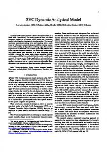
ambient conditions. Some have been in operation for over 20 years while others have only three years in service. The typical transmission SVC is a vernier controlled device consisting of applicable combinations of Thyristor Switched Capacitor banks (TSC), Thyristor Controlled Reactors (TCR) and fixed filter banks as required. The reactive branches are connected to a MV bus and connected to the transmission voltage level through a step up transformer. There are also discretely controlled SVCs consisting solely of TSC branches or of Thyristor Switched Reactors (TSR) and TSC branches in combination. Both types are depicted in figure 1 but it should be said that the latter type is not as common as the vernier controlled device even though there are a decisive number of discretely controlled SVCs in operation world wide. From the perspective of this paper the properties of the two types can however be treated equally.
Index Terms--Static Var Compensator (SVC), ancillary systems, Reliability-Availability-Maintainability (RAM),
S
I. INTRODUCTION
tatic Var Compensators have been used in transmission systems since the 1970s. This paper aims to show the support provided by SVCs during system contingencies and also the availability and reliability issues necessary to address in order to secure the SVC operability when called upon to operate. The SVC’s referred to in the paper are of different backgrounds with respect to years in operation and
Alwyn Janke is with Powerlink, QLD Australia, email:
[email protected] John Mouatt is with TransGrid, NSW Australia, email:
[email protected] Ron Sharp is with PG&E, California USA e-mail:
[email protected] Hubert Bilodeau is with Hydro Quebec, Canada e-mail:
[email protected] Anders Bostrom is with ABB Powersystems FACTS, Sweden e-mail:
[email protected] Mikael Halonen is with ABB Powersystems FACTS, Sweden email:
[email protected] Bo Nilsson is with ABB Australia Pty. Ltd, Australia email:
[email protected]
978-1-4244-6551-4/10/$26.00 ©2010 IEEE
Figure 1: Example of SVC configurations
There are also SVC configurations based on TCR and filter banks that are generally used for traction load balancing and industrial purposes such as flicker compensation. II. SVC RESPONSE DURING NETWORK CONTINGENCIES Transmission SVCs are primarily installed to provide dynamic support during and directly after network contingencies. The SVC will support the system during the voltage recovery stage after clearance of a fault and reduce the risk of voltage collapse. A. The PG&E Potrero SVC Event Recording An example illustrating this is given in detail in [1] where recordings from the PG&E Potrero SVC at a severe transmission line fault in the PG&E system close to San Francisco. For background on this particular case it can be said that there are two SVCs in the San Francisco bay area and both are involved in this event. One is the Potrero SVC, located in the City of San Francisco itself and the other at
2
Newark in the South Bay area. Both units are of similar size and configuration with an operational range of 240 Mvar capacitive to 100 Mvar inductive and 220 Mvar capacitive to 100 Mvar inductive respectively. The SVC topology in both cases consists of one TCR, one TSC and two filter branches tuned to the 5th and 7th harmonics. An interesting detail here is that the event itself was well documented by dispatch event recording during the fault giving the ability to go back and recreate the fault in the system models used for dynamic simulations during the early project design stages. This presented a rare opportunity for comparison of the system dynamics during an event like this with and without SVCs. The event recording from the Potrero SVC and the result from the simulations referred to are shown in figure 2 and 3 respectively. File: CNT Potrero SVC 1 20050119 07;51;29_240000.CFG 2
UP1_C [PU] UP1_B [PU] UP1_A [PU]
1 0 -1 -2
0
0.2
0.4
0.6
0.8
1
1.2
1.4
1.6
0
0.2
0.4
0.6
0.8
1
1.2
1.4
1.6
0
0.2
0.4
0.6
0.8
1
1.2
1.4
1.6
0
0.2
0.4
0.6
0.8 Time [s]
1
1.2
1.4
1.6
VRESP [PU]
0.2 0 -0.2 -0.4 -0.6
3
BREF [PU]
2 1 0 -1
Q_SVC [PU]
4
2
0
-2
Figure 2: Event recording of the Potrero SVC during a transmission line fault in the PG&E system. Traces from the top: 115 kV bus line to ground voltage (UP1_A, UP1_B and UP1_C), 115kV bus voltage response (VRESP), SVC susceptance reference (BREF) and SVC Mvar output (Q_SVC) at 100MVA base.
Figure 3: Simulation of the PG&E event captured in figure 2.
Of interest to observe here are the simulation results showing what would have happened to the system voltage with one or both SVCs off line. As seen in the top trace of figure 3 the simulations indicate that the system voltage would show a slower recovery with the Potrero SVC out and that it would not recover at all with both SVCs out. III. RELIABILITY EXPERIENCES The primary purpose of a transmission SVC is to provide dynamic support during contingency situations occurring during peak or off peak conditions. To maximize the SVC readiness for these events it is important to have a well adapted reliability concept involving all parts of the SVC installation. It is well known that the majority of the problems are related to ancillary equipment such as auxiliary power, valve cooling system and to some extent the control system. When analyzing problems related to these systems it is important to identify the root cause. Often a cooling or control system failure turns out to be caused by an unreliable auxiliary power system. Main circuit equipment, properly rated, is subject to a relatively low fault rate by comparison. Although it is theoretically possible to obtain availability approaching 100% this can not be done without introducing excessive redundancy that in turn will result in increasing complexity of the SVC unit. Realistically a total annual operational availability figure in the range of 99% to 99.5% can be reached with redundancy in the abovementioned sensitive parts and a proper amount of spare parts coordinated to meet the required availability. This is including both forced and scheduled outages in addition to time to get the repair crew on site. Overall annual reliability requirements representative of most SVC specification are in the range of 98% to 99%. It is however important to recognize that it is not the availability figure alone that determines the reliability of the SVC. Reliability is primarily driven by the number of failures. In a specification, beside the availability requirement, it is therefore equally important to specify the number of allowed forced outages over a selected time period, e.g. one year. This tells the manufacturer to what extent redundancy will have to be implemented. This applies to redundancy enabling the unit to stay on line with selected components or/and subsystems faulty. For SVC’s the most obvious and well known component where this concept is applied would be the thyristor. Thyristor valves normally are required to have at least one redundant thyristor level or a minimum of 10% redundancy. Other important subsystems subject to stand-by redundancy are auxiliary power (ac and dc), cooling system pumps, heat exchanger fans and control system. Many problems are caused by unreliable auxiliary power systems, specifically ac supply. To avoid problems it is important to design auxiliary systems to facilitate safe and reliable switchover between redundant sources and equipment. Situations where this is critical often coincide with network contingencies, which of course is exactly when the SVC support is needed. Hence the design of auxiliary power supply is a central issue to a reliable SVC design.
3
With control system spares readily available, a faulty circuit board is easily replaced. With the short down time this type of fault represents the availability is virtually unaffected. Nonetheless, the readiness of the SVC is zero during this time should it be called on to operate. Cold stand-by equipment, like transformers, de-energized redundant filter banks etc. have great impact on the availability figures as it keeps the downtime short. It does however not affect the number of forced outages and consequently does not contribute to the reliability of the SVC system. Although the failure rate for main circuit equipment such as transformers and reactors is low, such failures generally have big impact on the availability if spares are not held. Regarding transformer spares a common strategy when using single phase banks is to keep a fourth single phase unit as spare. When using three phase transformers the odd case requiring transformer spare units does occur but are not that common. For this type of component the decision to carry spares has to be made by the user weighing cost against consequences of failure. A. PG&E SVC Reliability Experiences Pacific Gas and Electric has two SVC’s, both located in the San Francisco bay area. The first was installed at Newark Substation in 2002 and the second at Potrero Substation in 2004. In general they both have provided a high level of reliability and high availability. It is estimated that the operational availability of these SVCs is approximately 98%, where 1% of the downtime is related to the equipment itself and the remaining 1% is related to crew delay time. These numbers are well in line with what was originally specified. Below are a number of events that have affected the availability of the two SVC’s. Newark SVC experienced a number of early control/software problems; these were corrected during the first few months of operation. Another early problem was an outage and reports of smoke from one valve stack. This problem was caused by a loose connection on a snubber resistor on the valve stack, only minor damage occurred. Cooling system leaks and pump motor problems have caused a number of scheduled outages for repairs. The SVC at Newark has had two outages caused by bird contact on the extensive exposed outdoor 21.5kV bus work, no damage was caused. The most recent outage occurred during a transfer of auxiliary ac power to the SVC. The problem was determined to be not re-setting an alarm that occurred during an earlier ac source transfer. Potrero SVC also has had outages caused by cooling system problems and auxiliary ac power supply. One trip occurred following a transmission system voltage dip. The SVC responded correctly to the voltage dip, but an under voltage protection of the cooling system did not have sufficient time delay and called for an unnecessary SVC trip. A minor software change corrected this problem. Other outages were caused by: broken cooling level sensor, disconnect position indication switch failure and a false TSC unbalance trip.
B. TransGrid SVC Reliability Experiences Since the mid 1980s TransGrid has installed a total of 7 transmission SVCs. These include small SVCs at the end of long lightly loaded transmission lines to large SVCs within urban load areas. The functions vary from providing transient stability support to voltage stability control and voltage regulation duty. Over the long term these SVCs have provided reliable service. There have been a number of major incidents but many minor and sometimes persistent problems have impacted on availability and/or increased the maintenance burden. Table 1 section IV summarises TransGrid SVC forced outages for the period 2002 to 2009. This Table covers 6 SVCs in the period 2002 to 2004 and 7 SVCs from 2005 to 2009. The most common sources, from within the SVC, for forced outage events have been Control & Protection and Cooling Plant. External factors, predominantly SVC earth faults (caused mainly by animals and vegetation) and some site specific issues have also caused a number of forced outages. Length of forced outages depends very much on the availability of spares and ease of repair. Below is a brief summary of the major issues associated with TransGrid’s SVCs since their commissioning. Both the SVC transformers in the two Kemps Creek SVCs have now failed. The first failure occurred after only 6 weeks of commercial service. This was an explosive failure with extensive fire damage of the transformer. No definitive cause could be found but it was suspected that the cause was related to manufacturing issues rather than any adverse interaction between the SVC, the power system and the transformer. One SVC was out of service for 8 months and the other for 20 months whilst a new transformer was built. The second transformer of the original two SVC transformers failed after 14 years of service. In this case the transformer fortunately tripped without explosion and fire. Inspection of the transformer windings showed a section-to-section failure in the HV disc winding. The short-circuit forces had been sufficient to jolt the transformer, activating the mercury switches in the winding temperature indicator and hence tripping the transformer. Again the failure was attributed to manufacturing issues. The Kemps Creek SVCs also suffered a TSC valve failure due to the cracking of a fibre glass structural component. The problem resulted from out-of-tolerance bolt holes in early production. The solution was to rebuild the thyristor modules and reduce the thyristor clamping pressure which had no consequence for the rating of the SVCs. An interesting problem exists at TransGrid’s Broken Hill substation when switching substation transformers. A process of transferred saturation creates a long-lived inrush transient which feeds into the tuned filters in the SVCs and occasionally trips the SVCs on filter protection. The obvious solution is to install controlled transformer switching.
4
Secondary plant and systems have caused more reliability issues than main plant. Some of these issues have resulted from design and some have resulted from the failure/ageing of equipment. Cooling plant has long been a source of problems within TransGrid SVCs. Most cooling plants have been subcontracted to local manufacturers who, whilst producing a robust piece of custom-made industrial plant, do not have the volume of work to develop a well-proven design for SVC usage. Besides leaks and failures of flexible couplings there have been problems with cooling plant controls. In some instances cooling plant controls and instrumentation were powered by substation ac supplies instead of substation dc supplies. When power system disturbances were reflected into the substation ac supplies the cooling plant control system would fail causing the SVC to trip exactly when it was required. In some instances instrumentation was not sensing flow rate changes sufficiently fast enough, leading to SVC tripping. Pump motor protection was sometimes based on protecting the motor rather than ensuring that the SVC continues to function through a power system disturbance. Protection relays used on the Armidale SVC were changed after several years because of false trips on energisation. High harmonic currents drawn by the tuned filters and inadequate harmonic restraint in the differential relays resulted in tripping. Whilst the differential relays were well proven for normal substation use they were not suitable for SVC use.
Figure 4: Armidale SVC – TransGrid
SVCs can also have significant environment impacts if not properly designed for the surrounding environment. Both Lismore and Armidale SVCs as originally constructed created excessive noise impacts. Both SVCs are located in quiet rural locations with nearby neighbours. Noise complaints at Lismore restricted operations to daylight hours for a period of time. Additional noise attenuating measures had to be installed at both locations resulting in early outages. Figure 4 shows typical noise attenuating walls erected around the SVC yard and its air core reactors, cooling plant heat exchangers and transformer.
Utilities need to exercise restraint and judgment when specifying requirements that cause a change to the manufacturer’s standard design. An example of this is TransGrid’s long-standing ban on epoxy resin current transformers which was a response to bad service experience in the past. This resulted in the use of locally made oil-filled CTs in the Lismore and Armidale SVCs despite the manufacturers’ preference for epoxy resin busbar CTs. Excessive conductor forces on the CT bushings, causing oil leaks, and also manufacturing issues have resulted in a continuing maintenance effort. TransGrid’s Broken Hill and Kemps Creek SVCs are now of the order of 20 years old and significant problems are affecting reliability and serviceability. Control system components are now very expensive or not available at all. Contractor and TransGrid knowledge and expertise in the now superseded control system technologies is becoming nonexistent or difficult to access. TransGrid is now making plans to refurbish these SVCs which will involve replacing control and protection systems, thyristor valves and cooling plants. C. Powerlink SVC Reliability Experiences Powerlink has nineteen SVCs in the transmission system throughout Queensland. Nine of the SVCs balance singlephase loads associated with electric coal haul locomotives in Central Queensland (Railways SVCs) while the other ten are conventional transmission application SVCs, providing dynamic var support to the transmission system. Problems were experienced during the early years of service of the Railways SVCs and the first transmission SVC [3]. The early problems were resolved and the SVCs have provided many years of reliable service. This paper summarises problems experienced more recently at two of Powerlink’s SVCs, one known as the Nebo SVC and the other known as the Ross SVC [2]. C.1 Nebo SVC A TCR valve at the Nebo SVC failed catastrophically due to a fire in the valve. It is thought that the fire was due to the failure of insulation on trigger pulse transformer boards in the valve. The SVC was successfully restored to service with a new TCR valve. The new valve required an interface panel between the original analogue control system and the new valve. Fires have occurred in two air cored tuning reactors at the Nebo SVC, figure 5.
Figure 5: Nebo SVC – Powerlink
5
It is believed that cracks in the inner fibreglass shells of the reactors allowed water to ingress to insulation material. It is thought that the water reduced the insulation properties of the insulation material and that the natural operation of the reactor lead to turn to turn failures. A shorted turn in a high magnetic field results in high currents, which in turn would have lead to an open circuit, arcing and eventually to an open fire. Flashovers have occurred within the SVC. In one case, a snake was found under a TSC valve. It is thought that the snake connected one corner of the delta connected SVC busbar to earth, putting a step increase in the voltage at the other two corners of the delta connection. It is thought that the step increase was enough to cause a first flashover. The first flashover allowed inrush current to the TSC capacitors to flow to earth, which caused a transient increase in the voltage on earth wires and on earthed metalwork within the control building. There were simultaneous flashovers from earth wires and earthed metalwork to phase at a couple of points within the building. Failed equipment was repaired or replaced and the SVC was successfully restored to service. In another case, there was no evidence of vermin that may have explained a first flashover. It is known that the TSC capacitors were charged and it is known that the first flashover occurred fifty milliseconds after the TSC switched off when the voltage across the valve would have been around two per unit. The first flashover allowed equalizing current to flow between TSC and FC capacitors, which caused a transient increase in the voltage on earth wires and on earthed metalwork in and around the control building. There were simultaneous flashovers from earth wires and earthed metalwork to phase at a couple of points within the building and at a wall bushing outside of the building. The SVC was successfully returned to service with a new TSC valve. C.2 Ross SVC During the early years of service, the Ross SVC tripped many times. In each case, the cooling water system initiated the trip of the SVC. There was sometimes a disturbance in the ac auxiliary supply to the SVC when the SVC tripped. An investigation determined that an instrument or transducer that was connected to the ac auxiliary supply was the root cause of most if not all of the unwarranted trips. The cooler controls were connected to the dc auxiliary supply to resolve this problem. The original coolers included aluminium tube, aluminium fin coil packs. Water began leaking from these coolers during the early years of service. An investigation determined that a combination of aqueous, crevice and pitting corrosion caused the leaks. The corrosion was exacerbated by cleaning of the coolers, both by adding moisture and a contaminating agent to crevices between tubes and fins. The aluminium tube, aluminium fin coolers were replaced by copper tube, copper fin coolers. Copper tube, copper fin coil packs were dipped in a bath of an acrylic liquid during manufacture. The acrylic liquid forms a coating on the fins and more importantly, it is believed that the acrylic fills or seals crevices between tubes
and fins and should reduce the risk of corrosion and subsequent failure. Low flow alarms occurred after the copper coolers were installed. Copper oxide had lodged in cartridge filters in the pump station and in waterways in the valves. It was believed that copper oxide was being carried from the inside of the copper tubes in the new coolers to various points in the cooling water system. There was a concern that copper oxide lodged in waterways in heat sinks and water-cooled resistors would adversely affect the cooling capability of these devices. It was determined that the pressure drop across heat sinks and water-cooled resistors in the Ross valves was around twice the pressure drop of new devices. Waterways in the valves were cleaned. There has been no obvious build-up of copper oxide since the valves were cleaned. Some days after copper oxide was cleaned from valve waterways, the Ross SVC tripped due to thyristor failures. The cooling water system stopped, but the SVC did not trip and two minutes and four seconds after the water stopped, the SVC tripped due to thyristor failure. Circuitry changes were made to ensure that the SVC would always trip if cooling water stopped. The disturbance recorder, installed to find out more about the unwarranted trips of the Ross SVC, was set to monitor communications between a main controller and the cooling controller. After some months of patiently waiting, the recorder proved that the link between the main controller and the cooling controller could be compromised. It is believed that some sort of interference to this link was the root cause of the thyristor failures. A phase to phase flashover caused two TCR reactors to fail at the Ross SVC. Torrential rain and vermin are believed to be contributing factors to the flashover. D. Hydro Quebec SVC Reliability Experiences Hydro-Québec TranÉnergie (HQT) 735 kV transmission system is characterized by a 1,000 km distance separating load centers from two main production centers. Between 1976 and 1988, fourteen Static Var Compensators were commissioned in eight different substations. SVCs are strategically located to overcome extreme contingencies including the loss of the HVDC Bipole. In addition, each installation consisted of two SVCs redundant to each other for meeting requirements on maintenance and operation. Originally, stability could be maintained and voltage control could be achieved with one SVC only in operation at each location. Over the years, however, all SVCs became essential. Those located on the northern grid closer to the generating centers contribute to the dynamic and transient stability whereas those closer to the load center contribute mainly to the voltage stability. Recently, voltage regulation duty became more important with increased load variation and demand. The need to maintain stability for normal contingencies was further addressed by the addition of 32 series capacitor banks in 1991 and network automation ensuring stability during extreme contingencies. As a consequence, the time response of all SVCs was increased. The need for specific reactive power elements to maintain network stability can be reassessed when 1 or 2
6
SVCs are out of commission for a longer period of time. However, once the SVCs are accounted for, reliability is expected during transient operation following an event on the network. This has not been the case in the early development of the technology. Furthermore, the loss of more than 2 SVCs simultaneously can gave rise to system instability and can provoke a general outage as it was observed in March 1989, when most of North America was hit by a very intense geomagnetic storm that caused seven Static Var Compensators to trip simultaneously. Adjusting upward the settings of protective relays sensitive to harmonic distortion within the design limits of the equipment have since improved SVC reliability under geomagnetic induced current (GIC) conditions [4]. Hydro-Québec never experienced over its 30 years of operation, unreliable behavior of SVCs at the time of contingencies except for Laurentides which was a prototype commissioned in 1978 and the case described above under GIC [6]. Laurentides [5] was designed with fixed capacitors and thyristor controlled reactor (FC/TCR) since the technology for thyristor switched capacitors (TSC) was not fully developed in the mid seventies. Many outages were experienced during the first two years after commissioning. Many thyristor failures following system faults were reported. From 1986 to 1990 many improvements were made to the control and protection system but yet major changes were needed on basic principles of voltage measurement, control strategy and thermal model. The decision to refurbish the installation was made after the ice storm of 1998 when the degradation of components in the control system made the repair in due time impossible. Regardless of the high life expectancy of thyristors, aging auxiliary components dictated also a complete valve replacement including the Valve Base Electronic and the Control and Protection system. The pumping station remained in good condition but replacement of rusted sections to the cooling tower and new piping was needed. The older control system behaved improperly on phase-tophase faults leading to failed thyristors during the recovery period. All previous deficiencies were completely eliminated after upgrading to a digital control system of a new generation. One month after the end of commissioning of the new control system, the system behaved as expected on a phase-phase fault. Major incidents can be expected over the long life cycle of the SVCs which can make them unavailable for a long period. However, it is important to minimize the down period and the solutions brought can lead to further improvement with increased reliability. Valve cooling was the cause of many outages in all the installations. Defective sensors, defective 3-way valves, outdoor coolers, pump permutation were the main sources behind these trips. Corrective actions have been taken quickly to solve these issues. Throughout the 1980s the installations at La Vérendrye and Chibougamau experienced many thyristors damages due to
misfiring from deficient thyristor firing circuitry. Cross-talk in the trigger channel along with unsupervised power supply was the source of these misfirings which were promptly corrected. In April 1998, a major fire occurs on a TCR valve on the upper section of phase B at La Vérendrye. The origin of the fire had been identified around the firing module. Four firing modules have been replaced within 3 months. This incident repeated itself 18 months later on the same valve and was finally replaced by a complete valve of a newer generation within one month. New maintenance methods were implemented with increased surveillance to the firing modules. Modifications to ground detection relay on valve side were implemented to accelerate the detection time response. Several outages occurring from 1993 to 1997 could not be related to a specific problem but were consequences of normal wear and tear of several components. A study revealed that control systems in most cases were responsible for these outages at Laurentides, La Vérendrye and Chibougamau. Availability of components and technical resources had a major impact on the long term reliability and availability of theses installations therefore the decision to replace the old analog control system was taken. The life of the installation at Némiscau and Albanel, an air-cooled FC/TCR of 12 pulse configuration commissioned in 1981, could be extended by the fact that enough spare parts were available or retrieved from the passive redundant control. In-house expertise contributed also to the replacement of control cards and parts of the valve assembly after a major fire occurred in one of the valve panels. Increased difficulty in maintenance and higher maintenance costs were decisive factors for planning a complete refurbishment by 2012. In 2003, an incident occurred on one phase of an air core reactor of the TCR branch at Chamouchouane. The fault was initiated in a turn-to-turn winding of the upper section and flashed over to the lower. Recordings of the reactor currents are shown in figure 6.
Figure 6: Event recording of the Chamouchaouane SVC TCR reactor failure. Traces from the top: TCR reactor currents (IdA, IdB, IdC), TCR line currents (IlA, IlB, IlC) bottom trace: negative sequence current (seqI).
7
Both reactors were replaced. A similar event occurred two years later.This type of faults within the reactors of TCR branches became a concern as such faults may not be detected by the existing protection devices.Static type negative sequence relays were used in earlier TCR valves but was abandoned for a control function which was not specifically designed to protect against TCR current imbalance. After the incident, it was recommended to install a protection scheme based on negative sequence since it was easier to implement in a short term. The relay for this function requires however a setting higher than the expected level of system unbalance and should be time-delayed to override external unbalance due to transient conditions. IV.
DISTRIBUTION OF FORCED OUTAGES
Operational RAM statistics seem to be scarce as far as SVC systems are concerned. It is therefore difficult to present hard figures in terms of reliability and availability percentages. Availability is generally difficult to asses based on historical data. The reason is that availability is depending on the outage duration, which may depend on a variety of factors. The owner may choose to delay repair until convenient, spares may not be readily available etc. Since details like these are extremely difficult to confirm with any accuracy for SVC units that have been in service for 15 years or more, it is recognized that using duration of outages as a measure does not give an adequate estimation of the availability. This is also consistent with the ongoing work of IEEE working group I4 of the Substations Committee, dealing with SVC reliability. It is more relevant to focus on the reliability of the SVC’s concerned within the scope of this paper. To get an understanding of the equipment involved, affecting SVC reliability, some crude statistics are available. When examining these figures it is important to bear in mind that the majority of the SVC’s have been in operation for 15 years or more. Table 1 shows the distribution of forced outages per utility. The format these figures are given in differs a little between the utilities. This explains why some fields are left blank, e.g. the main circuit is divided into subgroups where one utility presents data for the main circuit in total while another provides data per subgroup. In the table outages labeled external refers to faults caused by external factors, such as line to ground faults caused by animals and vegetation Source of Forced Outages 1. Main Circuit 1a. Main Circuit Capacitor/fuse 1b. Main Circuit Reactor 1c. AC Filter 1d. Thyristor Valves 1e. Power Transformer 1f. Disconnect Switches 5. Valve Cooling 6. Station Service 7. Control and Protection 8. External 9. Unknown
Table 1: Forced outage distribution
PG&E 0% 0% 0% 5% 0% 5% 16% 26% 42% 5% -
TG 15% 18% 16% 24% 20% 7%
PL 0% 1% 16% 2% 1% 2% 27% 8% 21% 20% 2%
HQ 3% 3% 0% 9% 5% 4% 30% 21% 25% -
The statistics provided for the two PG&E SVC’s matches well those of the other utilities with exception of the control. This is explained by initial control problems during the first few months of operation in the SVC first installed. Disregarding these initial failures the control failure share drops to 25%. The average number of forced outages per SVC from 2004 up to the present time is 0.75 outages per year. This should be considered when examining the PG&E statistics. The TransGrid (TG) statistics are valid for the period 2002 to 2009. Six SVC’s are covered from 2002 to 2004 and seven between 2005 and 2009. As indicated in Table 1 the main causes of SVC failures are valve cooling, control and auxiliary power. The average number of forced outages per year and SVC unit is 2.6 for the period with six SVC units and 1.6 for the period with seven units. To set this in to relation, requirements in SVC specifications are in the range