In the automotive industry, decision delay strategies have already been .... An important class of CSPs involves variables that have finite domains, i.e. all ...... Engineers may accept one night of computation, provided that an interesting analysis ...
Collaborative Design using Solution Spaces
` THESE No 2119 (2000) ´ ´ AU DEPARTEMENT ´ PRESENT EE D’INFORMATIQUE
´ ´ ERALE ´ ECOLE POLYTECHNIQUE FED DE LAUSANNE ` SCIENCES POUR L’OBTENTION DU GRADE DE DOCTEUR ES
PAR
Claudio LOTTAZ Informaticien diplom´e Universit´e de Berne originaire de Dirlaret (FR)
accept´ee sur proposition du jury: Prof. Boi. V. Faltings, directeur de th`ese Prof. James Bowen, corapporteur Prof. Gerhard Schmitt, corapporteur Prof. Ian. F. C. Smith, corrapporteur
Lausanne, EPFL 2000
ii
Abstract Complex design tasks from many domains such as mechanical, electrical and civil engineering make the collaboration of many partners unavoidable for several reasons: knowledge from various experts is necessary, often more than one enterprises are involved and deadlines impose concurrent engineering. However, collaboration also leads to certain inconveniences such as information loss and misunderstandings during communication and iterative negotiation when suggested partial solutions for subtasks conflict. Moreover, major problems are related to management of changes and ensuring design consistency. This thesis conjectures that many of these problems are caused by the use of single solutions during negotiation. Currently, project partners assign single values for sub-tasks and then proceed, often after tedious negotiations with other partners, to integrate these partial solutions into solutions for the whole project. While partners determine one single solution for a sub-task, much information about potential alternatives is lost and premature decisions are taken. The integration of partial solutions then often leads to artificial conflicts which are not due to incompatible design goals but arise because information about possible compromises is no longer available. Consequently, many changes usually occur during negotiation about parameter values and much effort must be invested in order to keep the design consistent. Therefore, we investigate the use of solution spaces instead of single solutions. When solution spaces are used during negotiation, more information about alternatives is available, premature decisions are avoided and thus, no artificial conflicts arise. Moreover, since project partners provide formal information about project requirements, real conflicts between diverging project goals can be detected. However, the implementation of a collaboration system using solution spaces is far from trivial, since in general the computation of exact solution spaces is intractable. We employ constraint satisfaction techniques in order to calculate solution space approximations. Constraints arise naturally in many fields of engineering and are therefore suited to formally express project requirements. Using constraints on design parameters, project partners can describe large families of acceptable solutions. Moreover, descriptions using constraints can be easily adapted to changes in the project’s context. When project descriptions in terms of constraints are available, constraint satisfaction techniques such as consistency can be employed to provide computational support during collaboration. Consistency algorithms use local inconsistencies to prune regions from the original search space where no solution can be expected and thus provide approximations of solution spaces. Algorithms which ensure low degrees of consistency provide a rough overestimation of the solution space but have low complexity, while algorithms which enforce high degrees of consistency provide a tight estimation of the solution space but suffer from iii
iv
ABSTRACT
high complexity. Since consistency algorithms provide over-estimations of solution spaces they are suited to find real conflicts between the various project requirements. In fact, using constraint satisfaction techniques in collaboration splits negotiation into two phases: negotiation of project requirements and negotiation about parameter values. During the negotiation of requirements, expressed as constraints, partners search for a feasible set of restrictions. Given such a set of restrictions, partners can negotiate about parameter values within the corresponding solution space approximation. During negotiation about parameter values some support for decision-making can be provided by analysing the shape of the solution space approximations. In order to illustrate the use of constraint satisfaction techniques in collaborative design, a prototype of an Internet-based communication platform has been implemented, which focuses on the exchange of data related to constraints and solution spaces, including the visualisation of constraints and projections of solution space approximation. It provides access to several constraint satisfaction algorithms. Moreover, some standard techniques were extended as follows: A reformulation algorithm transforms algebraic constraint satisfaction problems (CSPs) into ternary form, i.e., such that they contain exclusively constraints involving at most three variables. Thereby, few auxiliary variables are introduced and certain intermediary variables are removed in order to provide a small CSP in ternary form. In addition, the use of interval arithmetic techniques to discretise continuous constraints is proposed. Moreover, variants of 2-consistency and 3-consistency for ternary CSPs have been developed and an improvement of (3,2)-relational consistency’s space efficiency. Finally, a description of search heuristics for interactive use is described. The results of this research have been evaluated in the context of the construction industry. Construction projects are suitable test cases for collaboration systems, since they always imply complex interactions between several partners from various domains. With the help of practitioners, three realistic examples have been modelled. These projects demonstrate the usefulness of constraint satisfaction techniques during negotiation and collaboration within design projects. Constraint-based support leads to better management of changes and easier implementation of least commitment decision strategies. The results of this research may therefore improve the performance of collaboration systems currently in use.
R´ esum´ e La collaboration entre ing´enieurs pour r´ealiser de mani`ere efficace des projets complexes de g´enie m´ecanique, ´electrique ou civil est rendue n´ecessaire pour plusieurs raisons : la connaissance de plusieurs domaines est n´ecessaire, plusieurs entreprises sont souvent impliqu´ees et les d´elais forcent les participants `a travailler en parall`ele. N´eanmoins, la collaboration peut aussi causer des probl`emes, notamment des malentendus, des pertes d’information et des difficult´es pendant les n´egociations en cas de conflits cr´e´es par la confrontation entre des solutions partielles. Notre th`ese ici est que la plupart de ces probl`emes sont dus au fait qu’aujourd’hui les partenaires des projets utilisent des solutions isol´ees pendant les n´egociations. C’est-`a-dire que chaque participant ne propose qu’une seule solution pour sa partie du projet avant que ces solutions partielles ne soient int´egr´ees pendant des n´egociations souvent difficiles pour trouver une solution compl`ete pour le projet. Quand les ing´enieurs d´eterminent des valeurs uniques pour tous les param`etres, beaucoup de d´ecisions sont prises de mani`ere pr´ematur´ee, ce qui cause des conflits artificiels pendant les n´egociations. Ces conflits ne sont pas dus `a des buts de conceptions incompatibles, mais sont plutˆot une cons´equence de la perte d’information concernant des alternatives possibles. Cela implique que, pendant toute la conception du projet, de nombreux changements sont n´ecessaires et de nombreux efforts doivent ˆetre investis pour garder la coh´erence du projet. En r´eponse `a ces probl`emes, nous proposons ici l’utilisation des espaces de solution `a la place des solutions isol´ees. Cette approche permet de garder plus d’information concernant des alternatives possibles, ´evite la prise de d´ecisions pr´ematur´ee et ´evite ainsi des conflits artificiels. De plus, ´etant donn´e que les ing´enieurs formalisent leurs besoins, il devient possible de d´etecter des vrais conflits caus´es par des buts de conception divergents plus tˆot dans le projet. Bien que ce concept paraisse prometteur, sa r´ealisation n’est pas facile, parce que le calcul avec des espaces de solutions exacts n’est pas possible en g´en´eral. Nous proposons des techniques de satisfaction de contraintes pour calculer des approximations des espaces de solutions. Les contraintes sont pr´esentes dans de nombreux domaines de l’ing´enierie et peuvent donc servir `a exprimer formellement les conditions sur des projets. En imposant des contraintes sur des param`etres du projet, les participant au projet peuvent en fait d´ecrire des ensembles de solutions. De plus, la description utilisant des contraintes peut ˆetre adapt´ee facilement `a de nouvelles conditions de projets. Etant donn´e que des descriptions de projets sous forme de contraintes sont disponibles, des techniques de satisfaction de contraintes peuvent fournir un support de calcul pendant les n´egociations. Des m´ethodes de coh´erence utilisent des incoh´erences locales pour couper les parties de l’espace de recherche o` u l’on ne peut pas trouver de solutions et permettent v
vi
´ ´ RESUM E
ainsi de calculer une approximation de l’espace de solutions. Des algorithmes de coh´erence de bas niveau (tr`es locale) fournissent une surestimation grossi`ere de l’espace de solutions, mais sont efficace en complexit´e, alors que les algorithmes qui assure un degr´e ´elev´e de coh´erence (plus globale) d´eterminent une estimation plus pr´ecise mais sont de complexit´e plus importante. Parce que les algorithmes de coh´erence fournissent des surestimations d’espaces de solutions, ils sont adapt´es `a d´etecter des conflits dans les restrictions du projet. En fait, l’utilisation de techniques de satisfaction de contraintes pour la collaboration s´epare les n´egociations en deux phases : la n´egociation des conditions et la n´egociation de valeurs pour des param`etres. Pendant la premi`ere phase, les partenaires cherchent un ensemble acceptable de restrictions, exprim´e sous forme de contraintes. Etant donn´e un tel ensemble de contraintes, les participants au projet peuvent n´egocier les valeurs pr´ecises des param`etres en respectant l’approximation de l’espace de solutions correspondant. Pendant cette phase de n´egociation une aide `a la prise de d´ecisions peut ˆetre fournit en analysant la forme de l’espace de solutions. Pour illustrer l’utilisation de techniques de satisfaction de contraintes en collaboration dans la conception, un prototype d’environnement de communication sp´ecialis´e pour l’´echange d’informations li´ees `a des syst`emes de contraintes a ´et´e r´ealis´e. Il fournit entre autres des possibilit´es de visualisation de contraintes et de projections d’espaces de solution approch´es et permet l’acc`es commun `a plusieurs algorithmes de satisfaction de contraintes. Les extensions suivantes sont ajout´ees aux m´ethodes standards : Un algorithme de reformulation transforme des syst`emes de contraintes alg´ebriques en forme ternaire, c’est-`a-dire, de sorte que toutes les contraintes du syst`eme transform´e contiennent au plus trois variables. Pour g´en´erer un CSP petit, cet algorithme ´elimine certains variables interm´ediaires du syst`eme original et minimise le nombre de variables auxiliaires ajout´es pendant la ternarisation. De plus, l’utilisation de l’arithm´etique d’intervalles est propos´ee pour la discr´etisation des contraintes, des variantes de 2-consistency et de 3-consistency pour des contraintes ternaires sont d´evelopp´ees, et une am´elioration des performances de (3,2)-relational consistency relative `a l’utilisation de m´emoire est d´ecrite. Finalement, des heuristiques pour la recherche interactive sont d´ecrites. Les r´esultats de cette recherche sont ´evalu´es dans le contexte de l’industrie de construction. Des projets de construction permettent de tester de m´ethodes de collaboration parce qu’ils impliquent toujours des interactions complexes entre plusieurs participants de domaines divers. Avec l’aide de plusieurs bureaux d’ing´enieurs, nous avons mod´elis´e trois exemples r´ealistes de projets de construction. Ils montrent l’utilit´e de techniques de satisfaction de contraintes pendant la n´egociation et la collaboration. Le support `a base de contraintes facilite la gestion de changements ainsi que l’implantation de strat´egies least commitment. Les r´esultats de cette recherche peuvent par cons´equent am´eliorer l’efficacit´e des syst`emes de collaboration actuels.
Acknowledgements Probably the most important thing I learnt during this work about collaboration is, how important is smooth and efficient collaboration in order to successfully accomplish a complex task such as writing a thesis. Therefore, acknowledging all the people involved is an honest desire to me. I wish to address my sincere thanks to Professor Boi Faltings, who gave me the opportunity to work at the AI-Lab of the Swiss Federal Institute of Technology, for giving me much freedom in my work and for his constant encouragement during my time in Lausanne. I am very grateful also to Professor Ian Smith. He was responsible for both research projects I was working for and was therefore directly involved in my work. His pragmatic views on engineering protected me from loosing contact with the real worlds and during discussions with him many of the ideas in this thesis emerged. He also encouraged and supported me during the elaboration of most of my publications. Furthermore, I would like to thank the Professors James Bowen and Gerhard Schmitt for participating on the jury for this thesis, for in-depth discussions and comments. The theoretical foundation of the constraint techniques used on this research have been elaborated by Dr. Djamila Sam-Haroud. I would like to acknowledge her continued support and consulting in all questions about constraint satisfaction problems. The evaluation of my work was only possibly through the close collaboration with industry partners and civil engineers from the Civil Engineering Department of the EPFL. I would like to thank Andr´e Fl¨ uckiger from Zwahlen & Mayr who directly or indirectly provided all information about the 3 collaboration projects analysed during evaluation and I am particularly grateful to Denis Cl´ement, Yvan Robert-Nicoud and Etienne Fest for actually performing this analysis. In order to develop and implement the link to the ICC information environment many hours of close computer supported collaborative work with Professor Rudi Stouffs, Kuk Hwan Miwusset, Bige Tun¸cer, David Kurmann and Benjamin St¨ager were necessary. Many thanks therefore to the whole group which worked on this in CAAD of ETHZ. During my first two years in Lausanne Ruth Stalker was my closest collaborator. Together we realised a particularly successful project under the guidance of Professor Ian Smith. I would like to thank her for this collaboration and for continued discussions later on. During the actual writing of the thesis many people provided valuable comments. I would like to thank Esther Gelle for reading and very carefully commenting almost the entire thesis. I would also like to acknowledge the many comments by Marc Torrens, Ruth Stalker, Djamila Sam-Haroud, Steven Willmott,Lorenz Br¨ ugger, Marius Silaghi, Romaric Besan¸con and Christian Frei. vii
viii
ACKNOWLEDGEMENTS
I would like to thank Steven Willmott and Christian Bliek for encouragement and important comments on my work on reformulating numeric CSPs. I also received valuable input from Professor Ulises Cort´es during a trip to Barcelonna. Moreover, I am grateful to Monique Calisti for fruitful discussions about agent technology and negotiation. I would also like to thank all former and current members of the LIA, who helped creating a warm and joyful working environment. I would also like to thank my parents and my brother for their continued and generous support through my whole life. Their affection and warmth gave me the security and confidence I needed to achieve whatever I accomplished. This research has been funded and thus made possible by the Swiss National Science Foundation in two applied research project within the Priority Program on Computer Science.
Contents Abstract
iii
R´ esum´ e
v
Acknowledgements
vii
1 Introduction 1.1 Current Practice of Collaborative Design . . . . . . . . . . . . . . . 1.1.1 Paper-based Communication . . . . . . . . . . . . . . . . . 1.1.2 Electronic Communication . . . . . . . . . . . . . . . . . . . 1.1.3 The Crux of Current Collaboration Approaches . . . . . . . 1.2 Collaborative Design using Solution Spaces (CDSS) . . . . . . . . . 1.2.1 Augmenting Single Solution with Solution Spaces . . . . . . 1.2.2 Implementation using Constraint Satisfaction Techniques . 1.2.3 Support for Collaborative Negotiation and Decision-Making 1.3 Recent Research into Related Topics . . . . . . . . . . . . . . . . . 1.3.1 Computer Supported Cooperative Work (CSCW) . . . . . . 1.3.2 Collaborative Design and Concurrent Engineering . . . . . 1.3.3 Constraint Satisfaction Techniques in Collaborative Design 1.4 Guide to this Thesis . . . . . . . . . . . . . . . . . . . . . . . . . . 2 Collaborative Design using Solution Spaces 2.1 Traditional Approach using Single Solutions Only . . . 2.1.1 Artificial Conflicts . . . . . . . . . . . . . . . . 2.1.2 Undetected Real Conflicts . . . . . . . . . . . . 2.1.3 Responsibility for Design Consistency . . . . . 2.1.4 Management of Changes . . . . . . . . . . . . . 2.2 Augmenting Single Solutions with Solution Spaces . . 2.2.1 Negotiation about Project Requirements . . . . 2.2.2 Negotiation about Parameter Values . . . . . . 2.3 Representing Solution Spaces through Constraints Sets 2.3.1 Expressiveness of Constraint Sets . . . . . . . . 2.3.2 Constraint Satisfaction Techniques . . . . . . . ix
. . . . . . . . . . .
. . . . . . . . . . .
. . . . . . . . . . .
. . . . . . . . . . .
. . . . . . . . . . .
. . . . . . . . . . .
. . . . . . . . . . .
. . . . . . . . . . . . .
. . . . . . . . . . .
. . . . . . . . . . . . .
. . . . . . . . . . .
. . . . . . . . . . . . .
. . . . . . . . . . .
. . . . . . . . . . . . .
1 . 1 . 2 . 3 . 3 . 3 . 4 . 5 . 6 . 7 . 7 . 9 . 9 . 10
. . . . . . . . . . .
11 12 12 13 13 14 15 15 18 19 20 22
. . . . . . . . . . .
x
CONTENTS 2.4
Summary . . . . . . . . . . . . . . . . . . . . . . . . . . . . . . . . . . . . . 22
3 Implementing CDSS using Constraint Techniques 3.1 Consistency Algorithms for Ternary CSPs . . . . . . . . . . . 3.1.1 Local Consistency . . . . . . . . . . . . . . . . . . . . 3.1.2 Global Consistency . . . . . . . . . . . . . . . . . . . . 3.1.3 Consistency Algorithms . . . . . . . . . . . . . . . . . 3.1.4 Degrees of Consistency and Solution Spaces . . . . . . 3.2 Rewriting Numeric Constraint Satisfaction Problems . . . . 3.2.1 Constraint Arity and Consistency Algorithms . . . . 3.2.2 Removing Unnecessary Intermediary Variables . . . . 3.2.3 Making Constraint Satisfaction Problems Ternary . . 3.2.4 Complexity Considerations . . . . . . . . . . . . . . . 3.3 Discretised Constraints on Continuous Variables . . . . . . . 3.3.1 Spatial Data Structures to Represent Feasible Regions 3.3.2 2k -trees for Constraint Satisfaction Techniques . . . . 3.3.3 Generation of Feasible Regions . . . . . . . . . . . . . 3.3.4 Set Operators for Consistency Algorithms . . . . . . 3.4 Interactive Search for Single Solutions . . . . . . . . . . . . . 3.4.1 Searching with Minimal Change . . . . . . . . . . . . 3.4.2 Feasible Ranges . . . . . . . . . . . . . . . . . . . . . . 3.4.3 Illustration of Interactive Solution Adaptation . . . . 3.5 Summary . . . . . . . . . . . . . . . . . . . . . . . . . . . . . 4 Porting CDSS onto the Internet 4.1 SpaceSolver’s System Architecture . . . . . . . . . . . . 4.2 User Interface to the Worldwide Web . . . . . . . . . . . 4.2.1 Specifying Design Parameters and Constraints . 4.2.2 Management of Collaboration Projects . . . . . . 4.2.3 Visualisation of Constraints and Solution Spaces 4.2.4 Interactive Exploration of Solution Spaces . . . . 4.3 Linking to an Information Management System . . . . . 4.3.1 The ICC Collaboration Environment . . . . . . . 4.3.2 Linking the ICC Communication Environment to 4.4 Summary . . . . . . . . . . . . . . . . . . . . . . . . . . 5 Evaluating CDSS in the Construction Industry 5.1 Example 1: A Steel-framed Computer Building . 5.1.1 Project Description . . . . . . . . . . . . . 5.1.2 Describing the Problem using Constraints 5.1.3 Collaboration Structure . . . . . . . . . . 5.1.4 Ternarisation of the numeric CSP . . . .
. . . . .
. . . . .
. . . . .
. . . . .
. . . . . . . . . . . . . . . . . . . .
. . . . . . . . . . . . . . . . . . . .
. . . . . . . . . . . . . . . . . . . .
. . . . . . . . . . . . . . . . . . . .
. . . . . . . . . . . . . . . . . . . . . . . . . . . . . . . . . . . . . . . . . . . . . . . . . . . . . . . . SpaceSolver . . . . . . .
. . . . .
. . . . .
. . . . .
. . . . .
. . . . .
. . . . .
. . . . .
. . . . . . . . . . . . . . . . . . . .
. . . . . . . . . .
. . . . .
. . . . . . . . . . . . . . . . . . . .
. . . . . . . . . .
. . . . .
. . . . . . . . . . . . . . . . . . . .
. . . . . . . . . .
. . . . .
. . . . . . . . . . . . . . . . . . . .
25 26 27 28 29 40 41 43 44 46 49 50 51 54 55 59 62 63 66 66 68
. . . . . . . . . .
71 71 72 73 75 75 76 78 78 82 84
. . . . .
87 87 87 88 92 93
CONTENTS
5.2
5.3
5.4
5.1.5 Finding Real Conflicts . . . . . . . . . . . . 5.1.6 Planning Negotiations . . . . . . . . . . . . Example 2: Stacked Gymnastic Halls . . . . . . . . 5.2.1 Project Description . . . . . . . . . . . . . . 5.2.2 Collaboration Structure . . . . . . . . . . . 5.2.3 Finding Causes of Conflicts . . . . . . . . . 5.2.4 Approximations of Solution Spaces . . . . . Example 3: A Storage Hall with 50t Crane . . . . 5.3.1 Project Description . . . . . . . . . . . . . . 5.3.2 Making a CSP Treatable by Reformulation 5.3.3 Tradeoff Analysis . . . . . . . . . . . . . . . 5.3.4 Exploring Solution Spaces . . . . . . . . . . Summary . . . . . . . . . . . . . . . . . . . . . . .
xi . . . . . . . . . . . . .
. . . . . . . . . . . . .
. . . . . . . . . . . . .
. . . . . . . . . . . . .
. . . . . . . . . . . . .
. . . . . . . . . . . . .
. . . . . . . . . . . . .
. . . . . . . . . . . . .
. . . . . . . . . . . . .
. . . . . . . . . . . . .
6 Related Work 6.1 Communication and Information Management . . . . . . . . . . . . . 6.1.1 Shared Project/Product Models . . . . . . . . . . . . . . . . 6.1.2 Heterogeneous Agent Systems for Concurrent Engineering . . 6.1.3 Internet-Based Collaboration Environments . . . . . . . . . . 6.1.4 Management of Changes . . . . . . . . . . . . . . . . . . . . . 6.1.5 Management of Project Requirements . . . . . . . . . . . . . 6.1.6 Information Management in CDSS . . . . . . . . . . . . . . . 6.2 Conflict Management . . . . . . . . . . . . . . . . . . . . . . . . . . . 6.2.1 Avoiding Conflicts using Zones . . . . . . . . . . . . . . . . . 6.2.2 Design Rationale for Conflict Mitigation . . . . . . . . . . . . 6.2.3 Conflict Mitigation using Formal Domain Models . . . . . . . 6.2.4 Understanding and Classifying Conflicts . . . . . . . . . . . . 6.2.5 Constraint Checking for Conflict Detection . . . . . . . . . . 6.2.6 Weak Commitment by Management of Inconsistencies . . . . 6.2.7 Conflict Management in CDSS . . . . . . . . . . . . . . . . . 6.3 Conflict Resolution . . . . . . . . . . . . . . . . . . . . . . . . . . . . 6.3.1 Combining Agent Technology and Constraint Satisfaction . . 6.3.2 Conflict Resolution by Human Analysts . . . . . . . . . . . . 6.3.3 Rule-Based Conflict Resolution versus Genetic Algorithms . . 6.3.4 Conflict Resolution in CDSS . . . . . . . . . . . . . . . . . . 6.4 Negotiation Methodologies . . . . . . . . . . . . . . . . . . . . . . . . 6.4.1 Negotiation Support through Design Advice Tools . . . . . . 6.4.2 Progressive Negotiation among Collaborating Design Agents 6.4.3 Knowledge-Based Negotiation . . . . . . . . . . . . . . . . . . 6.4.4 Game and Negotiation Theory . . . . . . . . . . . . . . . . . 6.4.5 Negotiation Considerations in CDSS . . . . . . . . . . . . . . 6.5 Tradeoffs and Decision-Making . . . . . . . . . . . . . . . . . . . . .
. . . . . . . . . . . . .
. . . . . . . . . . . . . . . . . . . . . . . . . . .
. . . . . . . . . . . . .
. . . . . . . . . . . . . . . . . . . . . . . . . . .
. . . . . . . . . . . . .
. . . . . . . . . . . . .
94 94 96 96 97 100 102 103 103 107 108 111 111
. . . . . . . . . . . . . . . . . . . . . . . . . . .
117 . 118 . 118 . 119 . 120 . 121 . 122 . 123 . 123 . 123 . 124 . 125 . 126 . 126 . 126 . 127 . 128 . 128 . 128 . 129 . 130 . 130 . 131 . 131 . 132 . 133 . 134 . 134
xii
CONTENTS
6.6
6.5.1 Hierarchical Concurrent Engineering . . . . . . . . . . . 6.5.2 Constraints, Criteria and Optimisation . . . . . . . . . . 6.5.3 Supporting Collaboration through Decision-Maintenance 6.5.4 Tradeoff Evaluation . . . . . . . . . . . . . . . . . . . . 6.5.5 Advised Decision-Making . . . . . . . . . . . . . . . . . 6.5.6 Support for Decision-Making in CDSS . . . . . . . . . . Summary . . . . . . . . . . . . . . . . . . . . . . . . . . . . . .
7 Conclusions 7.1 Contributions . . . . . . . . . . . . . . . . . . . . . . . . . 7.1.1 Solution Spaces for Collaborative Design . . . . . . 7.1.2 Constraint Satisfaction Techniques . . . . . . . . . 7.1.3 A Communication and Collaboration Platform . . 7.1.4 Evaluation in Civil Engineering . . . . . . . . . . . 7.2 Limitations . . . . . . . . . . . . . . . . . . . . . . . . . . 7.3 Further Research . . . . . . . . . . . . . . . . . . . . . . . 7.3.1 Intuitive Interfaces . . . . . . . . . . . . . . . . . . 7.3.2 Data Structures for Representing Feasible Regions 7.3.3 Exploiting Sparsity of Problems . . . . . . . . . . . 7.3.4 Decomposition of Constraint Satisfaction Problems 7.3.5 A Priori Decomposition . . . . . . . . . . . . . . . 7.3.6 Distributed Solution of Decomposed CSPs . . . . . 7.4 Conclusion . . . . . . . . . . . . . . . . . . . . . . . . . .
. . . . . . . . . . . . . .
. . . . . . . . . . . . . .
. . . . . . . . . . . . . .
. . . . . . .
. . . . . . .
. . . . . . .
. . . . . . .
. . . . . . .
. . . . . . .
. . . . . . .
134 135 136 137 138 139 139
. . . . . . . . . . . . . .
. . . . . . . . . . . . . .
. . . . . . . . . . . . . .
. . . . . . . . . . . . . .
. . . . . . . . . . . . . .
. . . . . . . . . . . . . .
. . . . . . . . . . . . . .
141 141 141 142 143 144 144 145 145 146 146 147 148 148 148
Bibliography
149
Curriculum Vitae
161
List of Figures 1.1 1.2 1.3
Collaboration using subtasks. . . . . . . . . . . . . . . . . . . . . . . . . . . Intersection of solution spaces projected on common design parameters. . . Real conflicts are detected when solution spaces to subtasks do not intersect.
2.1 2.2 2.3
Plans used during early negotiation about dimensioning of holes in beams. . 15 Projection of simplified solution space for steel-framed building. . . . . . . . 17 Collaboration graph example. . . . . . . . . . . . . . . . . . . . . . . . . . . 21
3.1 3.2 3.3 3.4 3.5 3.6 3.7 3.8 3.9 3.10
Improved refinement of strong 2-consistency compared to arc-consistency. . Solution space approximations of different precision. . . . . . . . . . . . . . Rewriting a 5-ary constraint in terms of several ternary ones. . . . . . . . . Elimination of constants makes intermediary variable unnecessary. . . . . . 1 Quadtree for the constraint y ≥ arctan( x−2 ). . . . . . . . . . . . . . . . . . Illustration of a total constraint. . . . . . . . . . . . . . . . . . . . . . . . . A simple constraint with a complex feasible region: sin(x2 )+sin(y 2 ) < −0.25. Translation array for projection from [x, y, z] to [y]. . . . . . . . . . . . . . . Extended intersection is equivalent to composition. . . . . . . . . . . . . . . Interactive adaptation of a floor plan. . . . . . . . . . . . . . . . . . . . . .
34 40 41 42 54 55 58 60 62 67
4.1 4.2 4.3 4.4 4.5 4.6 4.7 4.8 4.9 4.10
SpaceSolver’s system architecture. . . . . . . . . . . . . . . . . . . . . . . . SpaceSolver’s Internet-based user interface for specifying CSPs. . . . . . . . SpaceSolver’s collaboration extension. . . . . . . . . . . . . . . . . . . . . . Three dimensional projection of a path consistent space. . . . . . . . . . . . Interactive exploration of solution space approximation. . . . . . . . . . . . View of the ICC prototype interface. . . . . . . . . . . . . . . . . . . . . . . A 3-dimensional visualisation of a project’s information structure. . . . . . Overview of the ICC architecture. . . . . . . . . . . . . . . . . . . . . . . . A SpaceSolver client can communicate and synchronise with an ICC client. SpaceSolver (top) navigates in the ICC environment (bottom). . . . . . . .
73 74 75 77 77 79 81 82 83 85
5.1 5.2 5.3
Construction site of the steel-framed computer building example. . . . . . . 88 Parameter definitions for holes in beams to hold ventilation ducts. . . . . . 89 Dependencies between partners through shared variables (Example 1). . . 93 xiii
2 4 6
xiv
LIST OF FIGURES 5.4 5.5 5.6 5.7 5.8 5.9 5.10 5.11 5.12 5.13 5.14 5.15 5.16 5.17 5.18 5.19 5.20 5.21 5.22
Negotiation plan for Example 1. . . . . . . . . . . . . . . . . . . . . . . Solution space approximation by (3,2)-relational consistency . . . . . . . Two triple gymnastic halls, one placed on top of the other. . . . . . . . Plans for stacked gymnastic halls example. . . . . . . . . . . . . . . . . Dependencies between partners through shared variables (Example 2). Negotiation plan for Example 2. . . . . . . . . . . . . . . . . . . . . . . Short walk through the information space corresponding to a CSP. . . . Longer walk through the information space corresponding to a CSP. . . Approximation of solution spaces for Example 1 . . . . . . . . . . . . . Storage hall with 50-tons crane and important security restrictions. . . . Parameters of storage hall example. . . . . . . . . . . . . . . . . . . . . Loads and maximum crane load hazard scenario for Example 3 . . . . . Chained elimination of unnecessary intermediary variables. . . . . . . . Two constraints after elimination of unnecessary intermediary variables. Optimisation criteria (z-axis), depend on column/beam flange width . . Pairwise tradeoffs for storage hall example. . . . . . . . . . . . . . . . . Overall tradeoff for storage hall example. . . . . . . . . . . . . . . . . . SpaceSolver’s interactive solution space explorer . . . . . . . . . . . . . . Moved wB in SpaceSolver’s solution space explorer . . . . . . . . . . . .
. . . . . . . . . . . . . . . . . . .
. . . . . . . . . . . . . . . . . . .
95 96 96 97 99 99 100 101 103 103 104 104 107 108 110 110 110 112 113
List of Tables 2.1 2.2
Evaluation of parameter values during negotiation. . . . . . . . . . . . . . . 13 Single solutions versus solution spaces in collaborative design. . . . . . . . . 23
3.1 3.2
Compare new generation methods with those proposed in [Sam-Haroud, 1995]. 58 Compare space efficiency of spatial data structures. Numbers in bytes. . . . 59
5.1 5.2 5.3 5.4 5.5 5.6
Definition of parameters for the steel framed building. . . . . . . . . . . Constraints providing requirements for a steel-framed computer-building Definition of parameters for the stacked gyms building. . . . . . . . . . Constraints related to dynamic and static aspects of the stacked gyms . Definitions of parameters for storage hall example (excerpt) . . . . . . . Constraints for the storage hall example (excerpt). . . . . . . . . . . . .
xv
. . . . . .
. . . . . .
90 91 98 98 105 106
xvi
LIST OF TABLES
List of Algorithms 3.1 3.2 3.3 3.4 3.5 3.6 3.7 3.8 3.9 3.10 3.11 3.12 3.13 3.14 3.15 3.16 3.17 3.18 3.19 3.20 3.21
Arc-consistency algorithm similar to AC-3. . . . . . . . . . . . . Initialise queue and labels for arc-consistency. . . . . . . . . . . . Revision step for conventional arc-consistency. . . . . . . . . . . . Determine arcs to be revised after successful revision of (i, j). . . Revision step for 2-consistency for ternary constraints. . . . . . . 3-consistency algorithm similar to PC-2. . . . . . . . . . . . . . . Initialise queue and labels for strong 3-consistency. . . . . . . . . Revise L( i, j) for path-consistency through k and Constraints. . Determine paths to be revised when label Lij changes. . . . . . . Algorithm for (3,2)-relational consistency. . . . . . . . . . . . . . Compile all total constraints into the labels. . . . . . . . . . . . . Revise Lijk for (3,2)-relational consistency, through u and v. . . . Determine 5-tuples to be revised after successful revision of Li jk. Eliminate constants and unnecessary intermediary variables. . . Simple algorithm to make one constraint ternary. . . . . . . . . Make numeric CSPs ternary. . . . . . . . . . . . . . . . . . . . . Generation of quadtrees for binary constraints. . . . . . . . . . . Determine the projection-array for quadrants. . . . . . . . . . . Project a tree of dimension d. . . . . . . . . . . . . . . . . . . . Extended intersection, a and b together contain d variables. . . Direct revision for (3,2)-relational consistency. . . . . . . . . . .
xvii
. . . . . . . . . . . . . . . . . . . . .
. . . . . . . . . . . . . . . . . . . . .
. . . . . . . . . . . . . . . . . . . . .
. . . . . . . . . . . . . . . . . . . . .
. . . . . . . . . . . . . . . . . . . . .
. . . . . . . . . . . . . . . . . . . . .
30 31 31 32 33 35 36 36 37 38 38 39 39 45 47 48 56 60 61 63 64
xviii
LIST OF ALGORITHMS
Chapter 1
Introduction Collaboration is unavoidable when solving complex design tasks. Usually such tasks can only be accomplished using knowledge from various domains, often more than one enterprises are involved and restrictions in time may require concurrent engineering. Therefore, several experts, who may work in different locations, must work together as smoothly as possible in order to solve complex design tasks efficiently. However, collaboration tasks are complicated by factors such as information loss and misunderstandings during communication, as well as iterative negotiation when subtask solutions conflict. Moreover, changes in context, costs, requirements, deadlines, etc. require constant re-negotiation of issues that may modify important project characteristics. These factors often cause important delays and can even lead to inconsistent designs. Correction of such inconsistencies in a late phase of a design project can result in additional costs as well as sub-optimal solutions. For these reasons, efficient and reliable techniques and tools for collaboration are needed. Such techniques should provide: • Facilities for efficient communication, • Improve negotiation between partners and • Support collaborative decision-making. In this thesis we propose a solution space in order to provide computational support for negotiation and collaborative decision-making. Constraints are used in order to formally represent project requirements and a communication platform on the Internet provides facilities for information exchange related to constraints as well as access to constraint satisfaction techniques.
1.1
Current Practice of Collaborative Design
Collaboration is common in many domains such as mechanical, electrical and civil engineering. Complex tasks are divided into independent or specialised subtasks such that 1
2
CHAPTER 1. INTRODUCTION
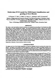
Figure 1.1: Collaboration using subtasks.
project partners can work on individual subtasks concurrently. All project partners negotiate in order to integrate subtask solutions into a solution for the whole task as illustrated in Figure 1.1. Communication and negotiation techniques must be established in order to collaborate between project partners in this way. Currently traditional ways of communication and negotiation are used.
1.1.1
Paper-based Communication
In many industry domains the traditional approaches to collaboration are still the state of affairs. Much paper work is needed to coordinate collaborators and serious problems and delays in communication and data exchange occur. In fact, physical meetings are often necessary in order to allow for efficient negotiation. However, such meetings are no longer always possible, because often collaborators work in geographically distant locations, thus, meetings are very expensive. For example, paper-based communication and negotiation as it is common in the construction industry caused problems in the following case. During the preliminary design of a steel-framed computer building to be built in Geneva (Switzerland), the architect decided to drill holes into floor beams, in order to pass ventilation ducts. This allowed at the same time to accommodate for the particular ventilation requirements for a computer building as well as the limited building height imposed by law. The architect suggested many large holes in the beams and sent the plans on to civil engineer. The civil engineer, worried about the static behaviour of the steel structure, suggested much fewer holes with just half the diameter. In consequence, the ventilation subcontractor objected, because the ventilation requirements could no longer be met. Since negotiation with plans sent back and forth by priority mail took too much time, the steel fabricator started to manufacture the beams before the negotiation was finished in order to keep up with the construction schedule. Unfortunately, the manufactured beams were eventually rejected. This led to additional costs and a significant delay. Efficient communication and negotiation could have saved thousands of dollars and much time.
1.2. COLLABORATIVE DESIGN USING SOLUTION SPACES (CDSS)
1.1.2
3
Electronic Communication
The advent of electronic communication methods such as e-mail at first glance seems to remedy the problem of inefficient communication. Indeed, electronic communication is fast and inexpensive. However, improved communication techniques also present risks. It is too simple to suggest changes. The responsibility for maintaining design consistency is often taken away from the initiator of a change. Instead, recipients of changes become solely responsible for approving changes. In complex projects, change recipients often become overwhelmed; they are no longer able to verify all suggestions due to the enormous amount of information received. In some cases, collaborators become very restrictive when confronted with new ideas in order to reduce the risk of error and inconsistency. In other cases, the integrity of the design project decreases while probability for missing deadlines and additional costs increase. In construction projects the responsibility for the static and dynamic integrity of a building is typically delegated to a civil engineer. Since almost any suggestion for a change involves verification of structural integrity, civil engineers are very likely to become overwhelmed by a mass of verification tasks. This partially explains why civil engineers have the reputation to prevent innovative ideas. Innovative ideas imply time consuming verifications by the civil engineer and an increased risk of error. Given the time-restrictions of construction projects, innovative ideas are indeed often dropped due to objections from civil engineers.
1.1.3
The Crux of Current Collaboration Approaches
Our hypothesis is that most of the problems encountered in collaborative engineering are due to the exclusive use of single solutions during negotiation. When project partners work on individual subtasks, they usually determine only single solutions for their subtasks, often represented by plans. In the process of determining a single value for all design parameters involved in the subtask many preliminary decisions must be taken. These decisions are often taken arbitrarily. Integration of partial solutions in order to obtain a solution for the whole task usually leads to artificial conflicts. Such conflicts may be less related to conflicting project goals than to premature decisions. Many of the preliminary decisions are revised in order to resolve these artificial conflicts. Unnecessary negotiation is, however, needed to resolve artificial conflicts and much effort is spent during this phase. In fact, the single solutions suggested by collaborators just demonstrate satisfiability of subtask requirements but rarely represent the only acceptable solution. Therefore, the exclusive use of single solutions in collaboration is insufficient.
1.2
Collaborative Design using Solution Spaces (CDSS)
In this thesis we suggest the use of solution spaces in addition to single solutions. Collaborators specify large families of acceptable solutions for their subtask. We conjecture that
4
CHAPTER 1. INTRODUCTION
augmenting single solutions with solution spaces has the potential to enhance collaborative design by providing support for collaborative negotiation and decision-making.
1.2.1
Augmenting Single Solution with Solution Spaces
When collaborators specify large sets of acceptable solutions for their specific subtask, they provide additional information about alternative solutions. Possibly they also determine one single solution to demonstrate the existence of a solution which satisfies all requirements. Such sets of acceptable solutions are in fact solution spaces. The impact of a certain subtask on other subtasks can be determined by projecting its solution space on the design parameters which are common to all subtasks. The intersection of all projections must contain all solutions for the whole task (see Figure 1.2). When this intersection is empty, no solution exists and not all design goals can be achieved simultaneously.
Figure 1.2: Intersection of solution spaces projected on common design parameters.
In order to describe solution spaces a formal description of project requirements is more efficient than enumeration of acceptable solutions for several reasons: • A formal description is more concise than the enumeration and is therefore easier to communicate. • A formal description can represents an infinite number of solutions. Given that many design parameters may be continuous, solution spaces are likely to contain an infinite number of solutions.
1.2. COLLABORATIVE DESIGN USING SOLUTION SPACES (CDSS)
5
• A formal description is easily adaptable to changes in the context of a project. Large parts of the description can usually be reused, the adaptation normally consists of adding or removing a small set of restrictions. Based on formal descriptions of project requirements, solution spaces and intersections of solution spaces must be computed automatically. The intersection of solution spaces is established more easily when project requirements are formalised. It is enough to determine the solution space of the conjunction of requirements imposed by all project partners. Therefore, formal descriptions of project requirements are used hereafter to describe solution spaces.
1.2.2
Implementation using Constraint Satisfaction Techniques
The practical implementation of the collaborative design approach using solution spaces is far from trivial. The exact representation and handling of solution spaces is intractable in general. However, constraint satisfaction techniques can approximate solution spaces in polynomial time and space. Constraint satisfaction techniques have the properties we need for an implementation of collaborative design using solution spaces for: • Constraint satisfaction problems (CSPs) are concise, formal representations of solution spaces. Constraints represent requirements. • Consistency algorithms compute solution space approximations for CSPs with polynomial time and space complexity. • CSPs occur naturally in many engineering disciplines. Therefore, engineers are likely to accept CSPs in collaborative work. A CSP is defined by a set of variables, their domains (a priori possible values for each variable) and a set of constraints. Domains of variables are either discrete or continuous. Discrete domains are enumerations of possible values while continuous domains are usually single intervals in 300, e < 1200. • Posted by engineer: x > 2d, d < 400, e > 900. • Posted by steel fabricator: x > 700, x > d + 50. Thereby the architect’s major concern is to ensure that enough, sufficiently large holes are provided to satisfy the ventilation requirements, while the engineer states the needs for the building’s structural integrity and the steel fabricator makes sure that wholes are not too close to the edges for trouble-free fabrication. This is a very rough approximation of the real example for illustration. ¡subsectionInterpreting Constraint Satisfaction Problems Structure Constraint satisfaction problems can be represented as graph for a binary CSP and a hyper-graphs for an n-ary CSP. A CSP is binary when all its constraints contain at most two variables. Constraints of an n-ary CSP contain at most n variables. Variables are represented as nodes of the constraint graph and constraints as edges which contain all variables of the corresponding constraint. The structure of a constraint graph gives hints about the nature of the CSP at hand. For instance, dense regions of the graph are likely to provoke more conflicts while sparse parts are likely to be solved quickly. If a constraint graph has tree structure it can be solved easily while the presents of cycles my cause serious problems during propagation of changes [Dechter and Pearl, 1989, Freuder, 1982, Gyssens et al., 1994]. The structure of a CSP in the context of collaborative design can also be used to illustrate dependencies between collaborators. We suggest to represent the collaboration structure of a collaborative design project as collaboration graph. The nodes of a collaboration graph represent project partners. When two project partners share variables, the corresponding nodes in the collaboration graph are linked and labelled with the set of shared variables. Collaboration graph show strong and weak dependencies between subproblems as well as cyclic dependencies which are particularly difficult to solve for the same reasons as cycles in constraint graphs. Figure 2.3 shows the collaboration graph for the example mentioned in Section 2.1.1.
Figure 2.3: Collaboration graph example.
22
2.3.2
CHAPTER 2. COLLABORATIVE DESIGN USING SOLUTION SPACES
Constraint Satisfaction Techniques
Constraint satisfaction techniques include suitable methods to handle approximations of solution spaces. By converting algebraic representation of CSPs into explicit spatial representation and subsequent application of suitable consistency techniques the inherent complexity of collaborative design using solution spaces can be kept under control. The conversion of the algebraic representation of constraints into spatial representations of their feasible regions avoids many analytical problems. Instead of the analytical treatment of intersections and composition of constraints, these operations can be performed on a geometrical representation, using well known methods and data structures from computer vision and graphics. Using spatial representations of feasible regions we also can use robust polynomial time and space methods to approximate high dimensional solution spaces, visualise projections and allow designers to explore solution spaces interactively. Both, visualisation and interactive exploration are interesting tools for decision-making in collaboration.
2.4
Summary
Many of the drawbacks associated with most currently used methods for collaboration in design can be derived from the fact that project partners only work with point solutions. We suggest to augment the point solutions in collaborative design with solution spaces. This breaks negotiation into two phases: negotiation about project requirements using solution spaces and negotiation about parameter values within the solution space. Several of the problems encountered in collaboration with single solutions do not occur in the solution space approach (see Table 2.2). Premature decisions as they are provoked when using single solution exclusively are not needed when designers can specify solution spaces. Therefore, no artificial conflicts occur. Moreover, real conflicts can be detected automatically when formal information about project requirements is available. When the context of a project changes specifications of solution spaces can mainly be reused while in the single solution approach complete renegotiation of all issues is triggered. In general, less iterations during negotiation are expected when using solution spaces. Furthermore, the automatic detection of real conflicts allows to delegate responsibility for design consistency to change initiators, such that change recipients are no longer overwhelmed by verification tasks as it is often the case when using single solutions. Negotiation about parameter values cannot be eliminated altogether. In order to decide which actual solution will be chosen, partners still need to agree in negotiations. During these negotiations, however, less objections are expected, because the negotiations are guided by the boundaries of solution spaces. Since consistency is guaranteed by computer support, we can also expect that partners will be less restrictive to innovative solutions. We propose the use of constraint satisfaction problems (CSPs) as concise description of solution spaces. Constraints in the form of mathematical relations such as equalities and inequalities are easy to manipulate, have a widely understood, unambiguous semantics and
2.4. SUMMARY Collaboration aspect Premature decisions Artificial conflicts Real conflicts Keep design consistent Changes in context
23 Single Solutions forced very likely difficult to detect change recipients complete renegotiation
Solution Spaces avoided avoided automatic detection change initiators reuse of previous work
Table 2.2: Single solutions versus solution spaces in collaborative design.
are compact enough for transmission through computer networks. Moreover, constraints in mathematical form provide a natural means to describe and represent project restriction, since much engineering knowledge is already provided in the form of constraints. Finally, the structure of CSPs represented in constraint and collaboration graphs reveals important information about dependencies between subtasks of different project partners. Tools to visualise and interactively explore solution spaces can be provided in order to support informed decision-making. The use of constraints and solution spaces helps to delay decisions for variable values until they become essential for the completion of the project. When premature decisions are reduced, information related to possible alternatives is retained. This is a variant of the least commitment paradigm often employed for planning tasks. In the automotive industry, decision delay strategies have already been adopted by major manufacturers (see [Ward et al., 1995]). In many practical cases, knowledge about a project cannot be modelled completely. Our approach does not require constraint sets to be complete. If a constraint is missing from the set, the real solution space may be smaller than the calculated approximation. Constraints that cannot be represented algebraically are expressed during negotiation by guiding the selection of the point solution in the solution space. Therefore, constraints should not be thought of as defining feasible solutions but rather, they are a delimitation of what is not possible. CSP techniques thus provide good support for interactive decisionmaking when complete knowledge modelling is not possible.
24
CHAPTER 2. COLLABORATIVE DESIGN USING SOLUTION SPACES
Chapter 3
Implementing CDSS using Constraint Techniques Although the solution space approach to collaborative design described in Chapter 2 is very promising, its implementation is far from trivial. In general, the exact representation and treatment of solution spaces is not tractable. Constraint satisfaction techniques, however, provide means to approximate solution spaces with polynomial complexity and are therefore used in this thesis to represent and compute with solution spaces. This chapter describes the techniques we propose for implementing collaborative design using solution spaces (CDSS). Collaborators specify the project requirements using constraints given as sets of mathematical relations expressed with unary and binary operators. Thereby, the variables involved have continuous domains, i.e., can take values from an interval in b where the domains of all variables are [0.0, 1.0]. The feasible region of these two ternary constraints are illustrated on the lefthand side of Figure 3.1. These two constraints do share
34
CHAPTER 3. IMPLEMENTING CDSS USING CONSTRAINT TECHNIQUES
x and y, thus they may allow some additional refinement through strong 2-consistency. When constraints are propagated individually through the arc (x, y) in this example, no refinement is possible, since both projections of the individual constraints on (x, y) cover the whole domains for x and y as shown in the centre of Figure 3.1. In contrast to conventional arc-consistency, strong 2-consistency as defined above considers the intersection of the projections of these constraints on (x, y) when revising the arc (x, y) as illustrated on the righthand side of Figure 3.1, and thus discovers the possibility to refine y’s label to [0.0, 0.5].
Figure 3.1: Improved refinement of strong 2-consistency compared to arc-consistency.
3-Consistency The impact of the result generated by arc- and strong 2-consistency algorithms is limited by the representation of their results through unary labels. The search space determined is a collection of cubes or hypercubes each edge of which is parallel to some axis and perpendicular to all other axes. More sophisticated shapes of search spaces can be determined by using higher dimensional labels. Strong 3-consistency, also called path-consistency, uses binary labels and makes all induced ternary constraints explicit [Freuder, 1982]. Adaptation to 2k -trees of the algorithms suggested for discrete binary CSPs were first proposed in [Sam-Haroud, 1995]. In contrast to 3-consistency algorithms suggested so far, the algorithm developed within this thesis not only treats binary but also takes ternary constraints into account. Let us add its formal definition here: Definition 3.5 A 2nd -order labelling L = {LV1 V2 , LV1 V3 , . . . LVn Vn } for a ternary CSP P = (V, D, C) is 3-consistent when for any (x, y) ∈ LXY where X, Y ∈ V and any Z ∈ V, there exists z ∈ DZ such that (x, z) ∈ LXZ , (y, z) ∈ LY Z and (x, y, z) satisfies CXY Z .
3.1. CONSISTENCY ALGORITHMS FOR TERNARY CSPS
35
Algorithm 3.6: 3-consistency algorithm similar to PC-2. function τ -3-consistency(Constraints) τ -3-init(Constraints, Q, L) while Q 6= ∅ do (i, k, j) ← pop(Q) if τ -3-revise(Constraints, i, k, j, L) then Q ← Q ∪ related-paths(i, j) end end return L end.
We propose a version of 3-consistency similar to PC-2 [Mackworth, 1977a]. Binary labels are continually refined as long as changes occur. Refinement is performed by propagating changed labels through ternary constraints. Similar to the arc- and 2-consistency algorithms described before, the sequence of refinements in τ -3-consistency (Algorithm 3.6) is controlled by a queue (Q) which contains all paths still to be revised. A path is a set of consecutive arcs. In the context of 3-consistency, paths always have length 2, i.e., they contain just two arcs which share at least one variable. Constraints contains the 2k -treerepresentations of the CSP’s total constraints. Algorithm 3.6 relies on three subroutines: • Initialisation of labels, constraints and queue (Algorithm 3.7) • Revision of a path taking ternary constraint into account (Algorithm 3.8) and • Determination of paths to be revised after successful revision (Algorithm 3.9). 3-consistency analyses subproblems of size three during revision. The standard version of strong 3-consistency, also called path-consistency, is defined for binary CSPs only [Mackworth, 1977a, Freuder, 1978]. We propose a generalisation to ternary constraints. In the revision step three variables are involved. In order to generalise the standard algorithm it is enough to intersect the composition of the two input-labels with the total constraint involving the three variables before projecting the result onto the output-label. In order to make sure that apart from the labels only ternary constraints must be treated during propagation, the initialisation described in Algorithm 3.7 compiles unary and binary constraints into the labels. Moreover, Q is initialised to contain all possible paths. Note that Lij is equal to Lji . In order to avoid computing too many labels, we suppose the there exists an ordering relation among variables and only compute labels with the lower index first. In analogy to PC-2 [Mackworth, 1977a] for discrete CSPs, τ -3-revise (Algorithm 3.8) revises the binary label Lij with respect to the path i − k − j and possibly the corresponding total ternary constraint in Constraints. It returns T RU E if a refinement was
36
CHAPTER 3. IMPLEMENTING CDSS USING CONSTRAINT TECHNIQUES
Algorithm 3.7: Initialise queue and labels for strong 3-consistency. procedure τ -3-init(Constraints, Q, L) Input: Constraints Output: Q,L Q ← {(i, k, j)|i, j ∈ vars(Constraints), i ≤ j, ¬(i = k = j)} Lij ← universal ∀i, j ∈ vars(Constraints), i ≤ j foreach C ∈ Constraints do if C is not ternary then if C is unary then {i} ← vars(C); Lii ← C; if C is binary then {i, j} ← vars(C); Lij ← C; remove C from Constraints end end end.
Algorithm 3.8: Revise L( i, j) for path-consistency through k and Constraints. function τ -3-revise(Constraints, i, k, j, L) Select C ∈ Constraints|{i, j, k} = vars(C) Q L0 ← Lij ⊗ i,j (Lik ⊗ Lkk ⊗ Lkj ⊗ C) if L0 = Lij then return F ALSE else Lij ← L0 ; return T RU E end.
achieved, F ALSE otherwise. ⊗ denotes intersection in the extended sense mentioned in Q Section 3.3.4, and therefore also represents the composition operator for 2k -trees. i,j C denotes the projection of C on the variables i and j. The function related-paths determines the paths to be revised when the label Lij is successfully refined. Similar to [Mackworth, 1977a], all paths are generated, which involve Lij when revised, i.e., all tuples of the form (i, j, k) or (k, i, j). The existence of a strict order on the variables is supposed in order to generate paths without duplicates. Correctness of τ -3-consistency 3-consistency ensures that when instantiating any pair of variables (i, j) within the label Lij determined by a 3-consistency algorithm, there exists a value for any third variable k such that all constraints of the CSP are satisfied. Algorithm 3.6 guarantees after exeQ cution that its revision step Lij ← Lij ⊗ i,j (Lik ⊗ Lkk ⊗ Lkj ⊗ C), where C is the total constraint which involves variables i, j and k, does no longer yield any refinement. Therefore, no value combination contained in Lij can be incompatible with C, Lik , Lkk or Lkj ,
3.1. CONSISTENCY ALGORITHMS FOR TERNARY CSPS
37
Algorithm 3.9: Determine paths to be revised when label Lij changes. function related-paths(i, j) if i = j then paths ← {(m, i, n)|m, n ∈ vars(Constraints), m < n, ¬(m = i = n)} else paths ← {(i, j, m)|m ∈ vars(Constraints), i ≤ m, m 6= j} ∪ {(m, i, j)|m ∈ vars(Constraints), m ≤ j, m 6= i} ∪ {(j, i, m)|m ∈ vars(Constraints), j ≤ m} ∪ {(m, j, i)|m ∈ vars(Constraints), m ≤ i} end return paths end.
otherwise this value would cause further refinement of Lij . The projections of other ternary total constraints on one or two of the variables i, j and k are taken into account through propagation. Lik , for example, only contains values which are compatible with any constraint C with vars(C) = {i, k, l}, since otherwise the revision of the path (i, l, k) would lead to a refinement. Thus τ -3-consistency as described in Algorithm 3.6 with its initialisation (Algorithm 3.7), revision step (Algorithm 3.8) and propagation (Algorithm 3.9) reliably computes strong 3-consistency for ternary CSPs. (3,2)-relational Consistency It can be shown that strong 3-consistency can achieve global consistency under certain partial convexity restrictions for binary CSPs, thus allowing backtrack-free search for solutions [Freuder, 1982]. A higher degree of consistency is needed to achieve global consistency for ternary CSPs. Under partial convexity restrictions similar to those for binary constraints, (3,2)-relational consistency can reach global consistency on ternary CSPs [Sam-Haroud, 1995]. (3,2)-relational consistency analyses subproblems of size 5 during revision. Its efficency in space has been improved in this research by not storing the intermediate 5-dimensional composition of labels during revision, without loosing efficiency in computation. (3,2)-relational consistency can be defined as follows: Definition 3.6 A 3rd -order labelling L = {LV1 V2 V3 , LV1 V2 V4 , . . . LVn Vn Vn } for a ternary CSP P = (V, D, C) is (3,2)-relational consistent when for any (x, y, z) ∈ LXY Z where X, Y, Z ∈ V and any U, V ∈ V, there exist u ∈ DU and v ∈ DV such that (x, u, v) ∈ LXU V , (y, u, v) ∈ LY U V and (z, u, v) ∈ LZU V . We describe in more detail the (3,2)-relational consistency algorithms proposed in [Sam-Haroud, 1995, Sam-Haroud and Faltings, 1996]. Ternary labels are continually refined as long as changes occur. Refinement is performed by propagating changed labels
38
CHAPTER 3. IMPLEMENTING CDSS USING CONSTRAINT TECHNIQUES
Algorithm 3.10: Algorithm for (3,2)-relational consistency. function τ -(3,2)-relational-consistency(Constraints) τ -(3,2)-init(Constraints, Q, L) while Q 6= ∅ do (i, j, k, u, v) ← pop(Q) if τ -(3, 2)-revise(i, j, k, u, v, L) then Q ← Q ∪ related-5tuples|(i, j, k) end end return L end.
Algorithm 3.11: Compile all total constraints into the labels. procedure τ -(3,2)-init(Constraints, Q, L) Input: Constraints Output: Q, L Q ← {(i, j, k, u, v)|i, j, k, u, v ∈ vars(Constraints), i ≤ j ≤ k, u ≤ v} Lijk ← universal ∀i, j, k ∈ vars(Constraints), i ≤ j ≤ k foreach C ∈ Constraints do if C is unary then unary :{i} ← vars(C); Liii ← C if C is binary then binary :(i, j) ← vars(C); Liij ← C if C is ternary then ternary : (i, j, k) ← vars(C); Lijk ← C end end.
through the network of labels. Similar to the consistency algorithms presented so far, the sequence of refinements in τ -(3, 2)-consistency (Algorithm 3.10) is controlled by a queue (Q) which contains all 5-tuples still to be revised. Constraints contains the 2k -treerepresentations of the CSP’s total constraints. Algorithm 3.10 relies on three subroutines: • Initialisation of queue and integration of constraints into the labels (Algorithm 3.11), • Revision of 5-tuple (Algorithm 3.12) and • Determination of 5-tuples to be revised after successful revision (Algorithm 3.13). The initialisation procedure is illustrated in Algorithm 3.11. It ensures that all total constraints are compiled into the labels. Since labels have the same dimension as the maximal dimension of the constraints, these constraints need no longer be treated. Algorithm 3.11 chooses one label for any constraint and intersects the label with the constraint,
3.1. CONSISTENCY ALGORITHMS FOR TERNARY CSPS
39
Algorithm 3.12: Revise Lijk for (3,2)-relational consistency, through u and v. function τ -(3,2)-revise(i, j, k, u, v, L) Q L0 ← Lijk ⊗ i,j,k Liuv ⊗ Ljuv ⊗ Lkuv if L0 = Lijk then return F ALSE else Lijk ← L0 ; return T RU E end.
Algorithm 3.13: Determine 5-tuples to be revised after successful revision of Li jk. function related-5tuples(i, j, k) return {(i, u, v, j, k)|u, v ∈ vars(Constraints), i ≤ u ≤ v}∪ {(u, i, v, j, k)|u, v ∈ vars(Constraints), u ≤ i ≤ v}∪ {(u, v, i, j, k)|u, v ∈ vars(Constraints), u ≤ v ≤ i}∪ {(j, u, v, i, k)|u, v ∈ vars(Constraints), j ≤ u ≤ v}∪ {(u, j, v, i, k)|u, v ∈ vars(Constraints), u ≤ j ≤ v}∪ {(u, v, j, i, k)|u, v ∈ vars(Constraints), u ≤ v ≤ j}∪ {(k, u, v, i, j)|u, v ∈ vars(Constraints), k ≤ u ≤ v}∪ {(u, k, v, i, j)|u, v ∈ vars(Constraints), u ≤ k ≤ v}∪ {(u, v, k, i, j)|u, v ∈ vars(Constraints), u ≤ v ≤ k} end.
thus preparing the labels for later propagation. Furthermore the queue of 5-tuples is such that each ternary label is revised through all pairs of variables at least once. The revision step shown in Algorithm 3.12 ensures that any partial solution chosen from within one ternary label can be extended to two more variables. Therefore, (3,2)-relational consistency is as strong as 5-consistency and has the same computational complexity although its result is more compact than the result of 5-consistency. 5-consistency would imply to store a quaternary label for every 4-tuple of variables, whereas (3,2)-relational consistency stores its result in ternary labels, one per triplet of variables. Therefore, 5-consistency has space complexity O(n4 ), while (3,2)-relational consistency has space complexity O(n3 ). (i, j, k) given to related-5tuples represent a label Lijk , which has been successfully revised and returns a set R of 5-tuples. R contains all 5-tuples, which cause (3, 2)-revise to use Lijk as input. Algorithm 3.13 assumes that i ≤ j ≤ k. Any 5-tuples (i, j, k, u, v) must satisfy the restrictions i ≤ j ≤ k and u ≤ v in order to benefit from the fact that Lijk = Likj = Ljik = Ljki = Lkij = Lkji . However, the algorithm as described here leaves some redundancy in the data, because it does not exploit the equivalence of binary labels Liij and Lijj separately.
40
CHAPTER 3. IMPLEMENTING CDSS USING CONSTRAINT TECHNIQUES
A major drawback of τ -(3, 2)-relational-consistency is hidden in its revision step (AlQ gorithm 3.12). The expression L0 ← Lijk ⊗ i,j,k Liuv ⊗Ljuv ⊗Lkuv implies an intermediary composition in 5 dimensions before projection onto (i, j, k). When implementing this revision step using matrices to represent labels, it is obvious that this intermediate result is not stored in 5-dimensional matrix before projecting it back onto a three dimensional matrix. Instead, the 5-dimensional composition is just computed implicitly while each of its elements is immediately projected onto the label to be modified. However, this procedure is not trivial when computing with 2k -trees. In Section 3.3.4 we describe, how direct revision of 3-dimensional labels for (3-2)-relational consistency can be implemented.
3.1.4
Degrees of Consistency and Solution Spaces
The reduced search space computed by consistency algorithms can also be interpreted as overestimating approximation of solution spaces. Figure 3.2 illustrates the different qualities of approximations provided by arc-, path- and (3,2)-relational consistency respectively. It shows projections of the arc-, path- and (3,2)-relational consistent spaces of an engineering problem onto the same three variables. The three variables chosen are not related by any direct constraints, the consistency algorithms compute the restrictions induced by other constraints. Since the representation of an arc-consistent space is a collection of unary labels, its projection onto three variables is a cube or in general a set of cubes (Figure 3.2a). The same projection of a path-consistent space is the intersection of three prisms, since it is represented using two dimensional labels (Figure 3.2b). (3,2)relational consistency uses three dimensional labels and thus provides general forms in 3d-projections (Figure 3.2c). Due to the simplicity of solution space approximations determined by arc- or 2consistency, these consistency algorithms do not reveal hidden relations between variables. Nevertheless they are efficient tools for finding conflicts in project requirements. Even for large examples these methods based on unary labels are able to detect conflicts within
(a)
(b)
(c)
Figure 3.2: Solution space approximations of different precision generated by arc-, pathand (3,2)-relational consistency (from left to right).
3.2. REWRITING NUMERIC CONSTRAINT SATISFACTION PROBLEMS
41
seconds. (3,2)-relational consistency is able to make hidden relations between originally unrelated variable explicit. In convex problems this method moreover allows for interactive exploration of the shape of the solution space. However, on large examples (3,2)-relational consistency cannot be computed due to its elevated computational complexity. Path- or 3consistency is a compromise between the two. Although, for ternary constraints it cannot determine labels which allow backtrack-free search, path- or 3-consistency approximates hidden relations and can detect in many cases. Moreover, its computational complexity allows for the analysis of real-world size problems.
3.2
Rewriting Numeric Constraint Satisfaction Problems
Rewriting numeric CSPs is useful for two reasons. Firstly, rewriting a CSP can be used to enforce a normalised form of the CSP as it is for instance needed by the consistency algorithms described in Section 3.1. Secondly, algebraic reformulation can lead to important simplifications and thus better performance for consistency algorithms [Lottaz, 1999a, Lottaz, 1999b]. The arity of a constraint is the number of variables it involves. The arity of a CSP is equal to the arity of the highest-arity constraint. Numeric CSPs are often reformulated in lower arity before computing consistency because CSPs of lower arity are considerably simpler to treat. Rewriting a numeric CSP in lower arity can be performed by introducing auxiliary variables for sub-expressions of high-arity constraints as illustrated in Figure 3.3. In fact, it has been shown that rewriting numeric CSPs in terms of ternary constraints is possible as long as only unary and binary operators occur in the constraints. It is intuitively clear that any mathematical expression built using unary and binary operators can be rewritten in ternary form by introducing an auxiliary variable for each intermediary result generated by a binary operator.
Figure 3.3: Rewriting a 5-ary constraint in terms of several ternary ones.
The condition that equalities and inequalities must be expressed using exclusively unary and binary mathematical operators holds for many practical applications. Therefore, consistency algorithms like 2-consistency as described in [Faltings and Gelle, 1997, Gelle, 1998] only accept ternary constraints. 2B- as well as 3B-consistency [Lhomme, 1993] are based on primitive constraints, which are also ternary in order to guarantee the robustness of the used projection operators. (r, r − 1)-relational consistency [Sam-Haroud, 1995]
42
CHAPTER 3. IMPLEMENTING CDSS USING CONSTRAINT TECHNIQUES
has exponential complexity in with respect to constraint arity. Therefore low-arity CSPs are treated much more efficiently by this algorithm. The rudimentary method to rewrite a numeric CSP in ternary form by introducing auxiliary variables for all binary operators, of course, possibly generates many new variables. Since the performance of all consistency algorithms mentioned above strongly depends on the number of variables involved in the given CSP, algorithms which introduce a small number of auxiliary variables are needed. So far, very few algorithms to perform the task of reformulating numeric CSPs in ternary form automatically have been suggested, the rewriting is often done by hand. In order to keep the number of variables in the final CSP low, it is also desirable to eliminate unnecessary variables from the original CSP. When formalising problems engineers and designers often use constants and intermediary variables which make the CSP more readable and reusable. However, in the context of computing consistency the elimination of such variables may decrease the number of variables of the ternarised CSP. Therefore, we suggest to apply elimination of unnecessary intermediary variables before performing ternarisation. Figure 3.4 shows the chained elimination of variables. In fact, the elimination of the constants QC , d1 and λ in the example extracted from a steelstructure holding a crane, shows that in fact Qrmax and QT r have become unnecessary.
Figure 3.4: Elimination of constants makes intermediary variable unnecessary.
The algorithms suggested in this chapter are particularly suited for consistency algorithms which treat ternary constraints without any restriction on the complexity of the constraints’ expressions. Examples of such algorithms are found in [Faltings and Gelle, 1997, Gelle, 1998, Sam-Haroud, 1995, Sam-Haroud and Faltings, 1996]. We improve existing suggestions, such as Algorithm 3.15, by removal of unnecessary intermediary variables from the original CSP and by optimising the number of auxiliary variables introduced. The next subsection contains theoretical considerations about the relation between constraint arity and consistency algorithms. Thereafter, the description of our algorithms for eliminating unnecessary variables of the original CSP and for rewriting numeric CSPs in ternary form are provided.
3.2. REWRITING NUMERIC CONSTRAINT SATISFACTION PROBLEMS
3.2.1
43
Constraint Arity and Consistency Algorithms
Treating high-arity constraints in consistency algorithms directly is very complex. Algorithms which enforce consistency on the symbolic level (e.g. [Gelle, 1998]), face important analytical problems when finding extrema, intersections and the like. Algorithms which use explicit spatial representations of the constraints (e.g. [Sam-Haroud, 1995]) spend an excessive effort to store these. The following considerations give an intuition about the benefits of computing (r, r − 1)-relational consistency on low arity CSPs instead of high-arity ones. In [Sam-Haroud, 1995] it has been shown that, for a CSP of arity r, given partial convexity restrictions (r, r − 1)-relational consistency is equivalent to global consistency, i.e., all solutions can be found without backtracking. Enforcing (r, r −1)-relational consistency, however, requires an algorithm with computational complexity O(n2r−1 ), where n is the number of variables in the CSP. As long as the convexity restrictions needed for global consistency remain satisfied in the CSP rewritten in lower arity, we can expect the results to be equivalent. Since the algorithm’s complexity is exponential in r, rewriting a numeric CSP in lower arity before computing (r, r − 1)-relational consistency has the potential to accelerate the calculation considerably. Numeric CSPs expressed as mathematical expressions using unary and binary operators can be rewritten with lower arity by introducing auxiliary variables. It is intuitively clear that by introducing auxiliary variables for the intermediary results of all binary operators in a constraint, the constraint’s arity can be reduced at the expense of increasing the number of variables (the auxiliary variables) and constraints (the definitions of the auxiliary variables). A constraint which defines an auxiliary variable that actually helps to reduce the arity of another constraint has at least arity three. Otherwise, the auxiliary variable would replace an expression which depends only on one variable by a new variable and could thus not reduce the arity of any constraint. Therefore, a numeric CSP rewritten in the above manner has at least arity three. On the other hand, arity three can always be reached by replacing every binary operator by auxiliary variables. So, on one hand decreasing the arity of a CSP before computing (r, r − 1)-relational consistency reduces the computational complexity. On the other hand, there is a tradeoff between decreasing arity and increasing the number of variables of the CSP by introducing auxiliary variables in order to achieve the lower arity. For deciding whether rewriting CSPs in lower arity pays off, we estimate how many auxiliary variables are introduced. Since (r, r − 1)-relational consistency is exponential in r, we only consider the case when the arity is reduced as much as possible, i.e., to arity 3. In the worst case, rewriting a numeric CSP of arity r > 3 in ternary form requires the addition of m auxiliary variables, where m is the number of binary operators in the CSP. In this case, the complexity O((n + m)5 ) for (3,2)-relational consistency on the rewritten constraint set compares to the complexity O(n2r−1 ) for (r, r − 1)-relational consistency on the original CSP. In practical problems, the exponential influence of r can be expected to
44
CHAPTER 3. IMPLEMENTING CDSS USING CONSTRAINT TECHNIQUES
outweigh by far the polynomial influence of m.
Moreover, several consistency algorithms for numeric CSPs are dedicated to ternary CSPs [Faltings and Gelle, 1997, Gelle, 1998, Lhomme, 1993, Sam-Haroud, 1995], since any numeric CSP expressed with closed mathematical expressions in unary and binary operators can be rewritten using ternary constraints exclusively. Nevertheless, few methods have been proposed to actually perform this task automatically. Known methods typically generate far too many auxiliary variables, such that subsequent computation of consistency is inefficient. Therefore, CSPs are often rewritten by hand although this may take several hours if not days for large examples.
3.2.2
Removing Unnecessary Intermediary Variables
In practice, engineers like to use constants and certain intermediary variables to make the formulation of their problem readable and adaptable to other situations, such that it can be reused later. This implies an extra cost in the number of variables. The efficiency of the consistency algorithms described in Section 3.1 highly depends on the number of variables in the CSP. Therefore, we suggest methods to detect and remove unnecessary intermediary variables. An intermediary variable is unnecessary, if it is unambiguously determined by an equality and if it does not contribute to keep the constraints ternary. Such variables can be substituted by the expressions by which they are defined.
3.2. REWRITING NUMERIC CONSTRAINT SATISFACTION PROBLEMS
45
Algorithm 3.14: Eliminate constants and unnecessary intermediary variables. procedure eliminate-unnecessary(constraints) while changes occur do foreach equality C ∈ constraints do foreach variable a ∈ C do if check-subs(a, C, constraints) then remove C from constraints substitute a in constraints break end end end end end. function check-subs(a, C, constraints) f ← solve C for a if f is not functional then return false foreach C 0 ∈ constraints do if substituting a in C 0 by f augments arity(C 0 ) above 3 then return false end return true end.
An intermediary variable a is defined in the CSP as the result of a functional expression a = f (x1 , . . . , xn ). It can be removed from the CSP by eliminating its definition from the CSP and by substituting a wherever it occurs in the remaining constraints of the CSP by f (x1 , . . . , xn ). However, substituting a is only enough to keep the CSP equivalent, when a is a constant. Otherwise, the information contained in the domain of a is lost and thus the new CSP is less restrictive. Therefore, the constraints a > f (x1 , . . . , xn ) and a< f (x1 , . . . , xn ) must be added where a and a are the lower and upper bound of the domain of a. Candidates for potentially unnecessary variables can be found in any equality. Solving an equality for one of its variables a yields the definition f (x1 , . . . , xn ) for a. However, this is only valid if f (x1 , . . . , xn ) is functional. Otherwise, for instance if the original equation was quadratic in a, substitution of a by f (x1 , . . . , xn ) in the CSP is not equivalent to its original. In the case of a quadratic expression, substitution of a by f (x1 , . . . , xn ) implies the loss of one of the two possible solutions for a. If a is a valid candidate for substitution, it should be substituted if its substitution does not increase the arity of any constraint to more than three. Removing a variable the substitution of which renders any constraint C non-ternary is unlikely to be useful in the context of making CSPs ternary, because it would imply an additional subsequent
46
CHAPTER 3. IMPLEMENTING CDSS USING CONSTRAINT TECHNIQUES
generation of at least one auxiliary variable in order to rewrite C in ternary form. Our algorithm implementing the elimination of unnecessary intermediary variables is shown in Algorithms 3.14. For illustration consider the following small example, a simplified problem from civil engineering: u < (3.18e−5 Hs + 0.0054)S Hs > 137.7 − 0.08633S + 5.511e−5 S 2 − 8.358e−9 S 3 p = u + 9.62 · 10−5 (0.0417W )1.5161 Hb > 0.077(pW 2 )0.3976 Hb > 0.0168(SW 3 )0.2839 This system of constraints contains the intermediary variable p which is defined here as p = u + 9.62 · 10−5 (0.0417W )1.5161 . The definition of p only involves the variables u and W . The only occurrence of p is in Hb > 0.077(pW 2 )0.3976 . Substituting p in this ternary constraint leaves it ternary because W is involved in both, the definition of p and the constraint where p is to be substituted. Therefore, p is an unnecessary intermediary variable and its elimination accelerates computing consistency. In order to keep the information of p’s domain, which is [15..50], we have to add the constraints 15 ≤ u + 9.62 · 10−5 (0.0417W )1.5161 ≤ 50. Since the substitution of a constant or an intermediary variable as described above may decrease the arity of a constraint, unnecessary variables are eliminated iteratively until no more changes occur. Not only those variables which are explicitly introduced by designers as intermediary variables match the definition of unnecessary intermediary variable. Mainly when designers decide to fix certain variables to constants, it is possible that any variable may be eliminated from the CSP. Sometimes this can lead to undesirable results, since the system may decide to remove variables, which are important for decisionmaking. Therefore, engineers can mark variables as crucial for decision-making. Such variables are not selected for elimination by the elimination algorithm.
3.2.3
Making Constraint Satisfaction Problems Ternary
It has been shown earlier that all numeric constraint satisfaction problems expressed with exclusively unary and binary variables can be rewritten in terms of ternary constraints. An obvious algorithm to perform this task, is to introduce an auxiliary variable for each binary operator. Each auxiliary variable represents the result of the binary operator it is attributed to. This algorithm has been implemented in early constraint packages, but even when regeneration of auxiliary variables for reoccuring expressions is avoided it introduces by far too many auxiliary variables. We suggest heuristics to find suitable expressions to define auxiliary variables such that fewer auxiliary variables are introduced. Our algorithm is able to define auxiliary variables using complex expressions while the standard algorithm only introduces auxiliary variables defined by expressions using at most one binary operator.
3.2. REWRITING NUMERIC CONSTRAINT SATISFACTION PROBLEMS
47
Our algorithm has shown in tests on practical examples from civil engineering that it introduces fewer variables than the standard algorithm (Algorithm 3.15) and performs almost as good as a reformulation by hand. This is because the expressions occurring in practical problems are often not particularly complex but frequently quite large, involving many operators. Introducing Auxiliary Variables A simple algorithm to rewrite a given CSP in terms of ternary constraints is suggested in [Gelle, 1998, Sam-Haroud, 1995]. It replaces any binary operator in a constraint by a new auxiliary variable which represents its result. This step is iterated until all constraints have arity three or less. (see Algorithm 3.15). Thereby the operands of the chosen operator do not contain any additional binary operator in order to avoid introducing non-ternary constraints when defining auxiliary variables. Algorithm 3.15: Simple algorithm to make one constraint ternary. procedure simple-ternarise(C) while C is not ternary do choose a subexpression e : xi ◦ xj of C substitute e in C by new variable xn+1 add the constraint xn+1 = xi ◦ xj end end.
This algorithm shows that it is always possible to rewrite a numeric CSP expressed using unary and binary constraints in ternary form but it generates far too many auxiliary variables for the following reasons: • It unnecessarily introduces binary constraints if xi or xj are constants, or both are a function of the same variable, • It does not allow the introduction of complex definitions for auxiliary variables, since only one binary operator is allowed and • It does not reuse auxiliary variables in other constraints or subexpressions. Some implementations improve upon the last critique about not reusing auxiliary variables by avoiding duplicate definitions. This allows for some optimisation, however, current algorithms do not try to provoke the reuse of auxiliary variables when choosing the expressions to define these. Therefore, many opportunities for reusing auxiliary variables are missed. We suggest a more general algorithm to perform the task of rewriting numeric CSPs in ternary form: In the first step, the constraints which already have ternary form are sorted
48
CHAPTER 3. IMPLEMENTING CDSS USING CONSTRAINT TECHNIQUES
out and are no longer manipulated. In the second step, the algorithm searches for an expression in two variables which occurs in one of the n-ary constraints. The third step is to substitute the expression found in step two in all non-ternary constraints. These three steps must be repeated until the list of non-ternary constraints is empty. Algorithm 3.16 illustrates this procedure. In step two, subexpressions involving exactly two variables are chosen because these expressions have the potential to decrease the arity of a constraint, and at the same time they do not add non-ternary constraints to the system. When a new auxiliary variable is added, its domain must be determined as well. Interval-arithmetic provides utilities to find upper and lower bounds for the auxiliary variables according to their definitions and the domains of the variables involved in their definition. However, when variables occur several times in an expression which defines a new auxiliary variable a, the domains of a may be overestimated. However this limitation is not important for existing local consistency algorithms. These algorithms can therefore be used to compute more precisely the domains of the auxiliary variables. On the other hand interval arithmetic guarantees that no solutions to the original numeric CSP are lost due to underestimation of domains. Algorithm 3.16: Make numeric CSPs ternary. function make-ternary(constraints) ternaries = ∅; i ← 1 while constraints 6= ∅ do foreach C ∈ constraints do if arity C ≤ 3 then move C from constraints to ternaries end Choose f (x, y) from ∪C∈constraints find-subexpressions(C) add auxi = f (x, y) to ternaries substitute f (x, y) by auxi in constraints i=i+1 end return ternaries end. function find-subexpressions(expr) if expr involves one or no variables then return (∅); if expr involves 2 variables then return (expr); subs ← ∅ foreach subset S of expr’s operands do e ← expression with expr’s operator on S subs ← subs ∪ find-subexpressions(e) end return (subs) end.
3.2. REWRITING NUMERIC CONSTRAINT SATISFACTION PROBLEMS
49
Defining Auxiliary Variables In order to find expressions for defining auxiliary variables, we must find subexpressions in two variables occurring in the CSP. This is performed by traversing the expression tree defined by the CSP. Whenever the traversing algorithm visits subexpressions involving exactly two variables, it stores them into a list instead of descending further into the expression tree. Thus no subexpressions of expressions in two variables are considered. What makes traversing an expression tree more complex than expected is that addition and multiplication are commutative. When we encounter the expression a + b + c, we have to consider a + b, a + c and b + c as possible subexpressions. In fact, computer algebra systems such as Maple V treat addition and multiplication as n-ary operators. Finding all subexpressions implies considering all subsets of an operator’s operands. findsubexpressions in Algorithm 3.16 returns subexpressions in two variables occurring in an expression. Thus it returns candidates for defining auxiliary variables. As soon as the candidate expressions are determined we must decide, which is the best expression to be used. Since we want to decrease the arity of all constraints below four, the sum of the arities of all non-ternary constraints is a reasonable criterion for minimisation. Therefore, we choose the candidate expression which decreases the arity of the most of the non-ternary constraints, breaking ties in favour of the candidates which generate the simplest constraints after substitution, i.e., the constraints with the fewest operands. The minimisation suggested above implies that common subexpressions are more likely to be chosen to define auxiliary variables. Therefore at first glance, factorisation seems to be appropriate in order to determine the common expressions. Indeed, factorisation is often helpful when common subexpressions are to be determined in one single expression. However, when searching for common subexpressions in several expressions, factorisation may actually hide opportunities. Consider the following example: ab + xz = 1,
cd + xy = 1,
e + xy + xz = 1
Introduction of the auxiliary variables aux1 = xy and aux2 = xz makes all these 4-ary constraints ternary. Had the third expression been factorised beforehand, it would look like this: e + x(y + z) = 1. The common expressions xy and xz are difficult to find in this situation. An automatic ternarisation algorithm is very likely to introduce three auxiliary variables in order to rewrite the factorised CSP: aux1 = ab, aux2 = cd and aux3 = y + z.
3.2.4
Complexity Considerations
Algorithm 3.14 eliminates unnecessary variables from a CSP. The outermost loop of eliminate-unnecessary is executed once for each constraint (c times), when all constraints can be eliminated. The second loop is called for each remaining constraint and the innermost loop is called r times in the worst case, where r is the CSP’s arity. Therefore, check-subs is called O(rc2 ) times, and performs its task in O(c). Thus, the complexity of Algorithm 3.14 is cubic in the number of constraints in the CSP and linear in its arity.
50
CHAPTER 3. IMPLEMENTING CDSS USING CONSTRAINT TECHNIQUES
The simple algorithm for making one constraint ternary (Algorithm 3.15) replaces all but two binary operators by auxiliary variables, because a constraint involving three variables has at least two binary operators. Thereby we consider the constraints in normalised form, i.e., with zero on the righthand side. The algorithm has to be launched for each constraint in the CSP. Hence the overall complexity is O(mc) where m is the number of binary operators and c is the number of constraints in the CSP. In order to estimate the complexity of our suggestion to rewrite a CSP in ternary form, we give the number of times the substitution of a candidate in the whole CSP is performed. In the worst case Algorithm 3.16 also introduces m auxiliary variables. For each of these, find-subexpressions, called on all constraints, finds O(c · 2RD ) subexpressions in the worst case, where R is the maximum arity of operands, and D is the maximum depth of expressions. Given that R and D are bounded, this yields that substitution is called O(mc) times. The complexity of the substitution itself is difficult to estimate, because we use the symbolic algebra package Maple V to perform this task. However, our experimental results show that Algorithm 3.16 can be used on problems of considerable size. Moreover, the computation of consistency by far outweighs this symbolic pretreatment in time cost.
3.3
Discretised Constraints on Continuous Variables
Constraints on continuous variables generally arise as algebraic equalities and inequalities involving several variables. Consistency algorithms which process constraints directly in this form and therefore encounter analytical difficulties related to operations such as intersecting surfaces and projecting volumes. In implementing consistency techniques for CSPs on continuous domains, a key problem is presenting and reasoning about valid combinations of variable values. Unlike valid value combinations for discrete CSPs, one cannot exhaustively enumerate valid value combinations when using continuous domains. For storing valid values for single continuous variables usually small sets of intervals are suited, whereas representing and manipulating valid value combinations of several continuous variables, as is necessary for computing higher degrees of consistency, is more involved since they may represent complex geometric shapes. This partly explains why the most prominent advances in numerical constraint satisfaction are related to 2-consistency, e.g. [Faltings, 1994, Faltings and Gelle, 1997, Lhomme, 1993, van Hentenryck et al., 1998]. In these approaches, labels to be determined are unary and thus can be represented easily. We propose the use of discretised constraints in order to cope with this problem to represent valid value combinations. Discretisation of constraints on continuous variables is useful in the context of consistency computation for two reasons: • Robust operations such intersection, composition and projection, and • Generic description of regions with arbitrary shape. The conversion of the algebraic representation of constraints into a spatial representation of their corresponding feasible regions leads to a logical rather than analytical treatment
3.3. DISCRETISED CONSTRAINTS ON CONTINUOUS VARIABLES
51
of feasible regions and solution spaces, thereby avoiding problems with singularities and other analytical problems. Robust algorithms for intersection and composition can be used in order to improve the reliability of consistency algorithms. The advantage of robustness is compromised by limited precision and bounded domains. Since an exact explicit representation of feasible regions using spatial data structures is in general not possible, a discretisation of the continuous space is needed and the feasible region must be approximated accordingly. Both restrictions are acceptable for approximation of solution spaces in many engineering applications. Nevertheless, an efficient data structure for storing and manipulating feasible regions has to be found. This section gives a comparison of some candidate spatial data structures and describes the use of 2k -trees for consistency computation.
3.3.1
Spatial Data Structures to Represent Feasible Regions
In [Sam-Haroud, 1995] it was first suggested to represent constraints and labels as discretised regions of feasible value combinations. Linear 2k -trees were used as the spatial data structure [Samet, 1990a, Samet, 1990b]. In spite of the ability of 2k -trees to aggregate homogenous regions into single nodes, it has been observed that these trees can grow in memory in a prohibitive manner. Therefore, an investigation about alternative data structures has been performed within this thesis. Extensive research on efficient data structures for representing regions has been undertaken in domains such as computer vision and geographic databases. These efforts lead to sophisticated solutions for compact representation of complex data. In the following we describe some of the results in the light consistency algorithms, i.e., with strong emphasis on efficient implementation of set operations such as intersection, composition and projection. Rectilinear Structures for Point-Data Much work on multidimensional data structures is done in the domain of multidimensional databases. Most of these approaches treat the problem to store point-data in an adequate way for efficient retrieval, and therefore usually use some hierarchical decomposition of the domain of the point-data. Such a decomposition might also be used to determine an efficient decomposition to represent regions as it is needed for representing constraints. However, no work for set operators such as intersection or projection is available and therefore major extensions would be needed to use such data structures in consistency algorithms. The k-D-tree [Samet, 1990b] stores point-data in a binary tree. At each interior node the space for the corresponding subtree is partitioned orthogonal to one of the axes into two sections. Several variants, where to store data (leaf nodes or interior nodes) and how to choose the exact place and direction of decomposition exist. The structure is very adaptable and therefore allows for very efficient search and storage, when all points to be stored are known beforehand.
52
CHAPTER 3. IMPLEMENTING CDSS USING CONSTRAINT TECHNIQUES
The MD-tree suggested in [Nakamura et al., 1993] improves the k-D-tree when points are not known beforehand but must be added one by one. In this case k-D-trees can become very unbalanced. Moreover, 50% of the nodes in the tree do not carry data. Each interior node in MD-trees has two or three children and only the leaf-nodes contain data. Algorithms for insertion and deletion of data elements which keep the tree balanced are described in [Nakamura et al., 1993]. In the database community there is much concern to this problem of dynamically inserting and deleting data while this is less important in our case, since during consistency algorithms feasible regions are not modified by single pieces of data but by set operations. Rectilinear Structures for Regions A hierarchical data structure commonly used in computer vision is the 2k -tree, called quadtree or octree in the two and three dimensional case. Space is bisected parallel to all axes at each step of decomposition. An efficient encoding of region quadtrees and octrees, linear quad-/octrees [Gargantini, 1982], are also used in [Sam-Haroud, 1995]. Nevertheless, more sophisticated coding and adaptable decomposition or storage of boundaries instead of regions can still improve compactness of data. The S-tree, as described in [De Jonge et al., 1994], is a very compact encoding of bintrees, quadtrees or octrees. The idea is to emit a bit-stream during a pre-order traversal of the underlying tree that reflects the structure of the tree in a very compact linear representation, which still allows quite efficient search. However, even though a modified S-tree [Chung and Wu, 1995] speeds up the search in such trees, logarithmic complexity, as it is possible for the original tree-structure, cannot be achieved. The S+ -tree, a variant of this structure, addresses the problem of pagination with very large images. The R-tree [Guttman, 1984] is closely related to the k-D-tree but adapted to storing rectangles instead of points. Each node is associated to a rectangular area. While leaf nodes contain the actual data-rectangles, interior nodes represent the smallest rectangle which encloses all rectangles associated to its subtree. Interior nodes have a limited but varying number of children. One of the advantages of this representation is, that it does not waste effort on “dead” space, i.e., empty regions. Although R-trees are height-balanced, the efficiency of search can decrease because overlapping of rectangles on the same levels is allowed and therefore several paths have to be searched in some cases. This problem is addressed by the R+ -tree [Sellis et al., 1987]. By allowing data-rectangles to be split it is no more necessary to overlap rectangles on any levels. Search is thus accelerated at the cost of splitting rectangles. Furthermore a packing algorithm exists to improve the compactness of an R+ -tree. Rechman et al. describe more work on insertion, deletion and search for R-trees in [Rechmann et al., 1990] (R*-trees) and [Kamel and Faloutsos, 1994] (Hilbert-R-trees). R*-trees were developed to improve R-trees when used on secondary storage systems, coping with problems such as page-faults. The Hilbert-R-tree in addition modifies the split-policy. The algorithms described split 2 leaf-nodes into 3 instead of 1 into 2. The
3.3. DISCRETISED CONSTRAINTS ON CONTINUOUS VARIABLES
53
Hilbert curve is used to establish a one-dimensional ordering of the rectangles which is needed for such splits. However, little work on spatial joins like intersection or union exists and no projection and composition algorithms have been developed so far. Non-Rectilinear Structures for Regions Decomposition of space using non-orthogonal hyper-planes leads to d-dimensional polyhedra. Such a representation to approximate constraints can be very compact and still more exact than a decomposition into cubes. Moreover, deficiencies concerning convex or connected regions as described in [Sam-Haroud, 1995] do not occur, since convex regions are always approximated using convex shapes. On the other hand a significant computational complexity for set operators, mainly the composition and projection is expected. A method similar to quadtrees is mentioned in [Samet and Webber, 1988]. It uses triangles instead of rectangles. The decomposition of these triangles results in a binary tree-structure. This structure might solve problems concerning deficiencies when intersecting convex regions as they are observed for quadtrees. However, no generalisation to three or even five dimensions is suggested so far, set operators as they are needed for consistency algorithms (composition and projection) do not exist. In [Gunther, 1988], some set operations and search algorithms on polyhedral chains are described. Polyhedral chains are sums of convex polygons. Convex polygons are represented as intersection of half-spaces and a union of such polygons makes up general polyhedra. Efficient manipulations on a vector representation of such polyhedral chains together with a tree organisation, the cell-tree, promise good performance on union, intersection and search. However, serious computational effort has to be expected for composition and projection. Moreover, detecting redundant half-spaces is very difficult and therefore combinatorial explosion is expected for iterative application of set operators. Binary space partitioning trees (BSP-trees) [Fuchs et al., 1980] are similar to k-D-trees but allow to use general hyper-planes to decompose the space instead of hyper-planes perpendicular to an axis. In addition, they are more intended to represent regions and not point data. BSP-trees are a subject of interest for the computer graphics community and were suggested to solve the problem to determine hidden lines. Some issues about how to generate good BSP-trees are outlined in [Naylor, 1992b, Naylor, 1993] and [Paterson and Yao, 1989] describes algorithms with complexity considerations to construct BSP-trees from boundary representations. Set operations for intersection and union are described in [Naylor et al., 1990, Naylor, 1992a], however, no algorithms for composition and projection are provided. The problem to polygonise a surface must be solved to find representations of constraints as polyhedra. This problem in three dimensional space is also encountered in computer vision. Some approaches are outlined in [De Figueiredo et al., 1992]. In conclusion of this comparison of data structures, it has been found, that several alternatives for more compact and more precise representations of feasible regions exist. However, 2k -trees offer by far the most efficient implementation of the set operations
54
CHAPTER 3. IMPLEMENTING CDSS USING CONSTRAINT TECHNIQUES
needed. Mainly projection poses serious problems for more complex data structures. In the context of consistency algorithms, it turned out that the computational complexity of set operators is more important for overall performance than the compactness of the data structure, since modern computers have enough memory to prevent page-faults. Therefore, we continue to use 2k -trees to represent discretised continuous constraints.
3.3.2
2k -trees for Constraint Satisfaction Techniques
2k -trees were originally developed in computer vision for concise representation of geometrical shapes [Samet, 1990a] and were later proposed for constraint satisfaction techniques in [Sam-Haroud, 1995, Sam-Haroud and Faltings, 1996]. Relations can be approximated through a hierarchical decomposition of its feasible space into quadtrees for binary relations and octrees for ternary ones. Figure 3.5 illustrates a binary constraint approximated using a quadtree. In two dimensions, this means that rectangles that are not completely feasible are subdivided into four smaller rectangles of equal size, each of which is re-tested recursively until the desired precision is obtained. Every square in Figure 3.5 corresponds to a leaf node in the quadtree and non-leaf nodes contain one child for each quadrant of the region they represent.
1 Figure 3.5: Quadtree for the constraint y ≥ arctan( x−2 ).
This hierarchical data structure is well adapted to the representation of feasible regions because they aggregate homogenous regions in order to represent them in a compact way. Continuous constraints very often contain large homogenous regions and therefore good aggregation can be expected. Although very space-efficient codings for 2k -trees such as S-trees [De Jonge et al., 1994]
3.3. DISCRETISED CONSTRAINTS ON CONTINUOUS VARIABLES
55
are known, we adhere to the basic pointer-based implementation. We found that in the context of consistency algorithms computational complexity predominates spatial efficiency when consistency algorithms are implemented avoiding large intermediary data structures. This is also due to our treatment of leaf-nodes. We allocate one white, one grey and one unknown leaf-node. Inner nodes which point to leaf-nodes contain pointers to one of these three instances according to the feasibility of the represented regions, thus avoiding allocation of additional memory for leaf-nodes. Constraints involving the same set of variables are stored in one total constraint. The original discretised constraint regions are intersected to form one single constraint, thereby simplifying the CSP and allowing for more pruning in many cases. An example for a total constraint is shown in Figure 3.6. The total constraint of variables a, c and t is the intersection of all constraints which involve a subset of these variables. In this figure a) and b) are spaces defined by individual constraints which form the space defined by the total constraint c).
3.3.3
Generation of Feasible Regions
Usually constraints of numeric CSPs are given in algebraic form, as equalities and inequalities. In order to generate explicit spatial representations of such constraints a discretisation is needed. It is supposed in this section that a constraint is given as a conjunction of equalities and inequalities, which involve at most three variables. Moreover, each variable has as initial domain one closed interval in 137.7 0.08s 0.02s p = u + 9.62E − 5(0.0417W )1.5161 11.73s 0.10s Hb > ((S · W 3 )0 .2839 ∗ 0.0168) 125.67s 0.15s wp = sin(φ2 − φ4 ) 98.50s 0.19s u = (x2 − x4 )2 58.13s 0.13s d > r1 + r3 85.75s 0.06s x4 = r4 cos(φ4 ) 58.56s 0.10s a = 0.08633, b = 5.511E − 5, c = 8.36E − 9 Table 3.1: Compare new generation methods with those proposed in [Sam-Haroud, 1995].
the fact that in our new implementation, C-source code is generated and compiled before generation of spatial data structures can take place. This preprocessing takes about 6 seconds and performing it once per CSP is enough, it is thus not very time-consuming. Moreover, in the case when we want to regenerate feasible regions for constraints, on refined domains for instance, no recompilation is necessary. Table 3.2 compares the memory needs of some spatial data structures for the examples already shown in Table 3.1. The structures compared are: a full pointer-based 2k -trees representation, which avoids storing leaf-nodes in the second column, a pointer-based representation which stores only feasible and partially feasible nodes in the third column, a pointer-less linear octree in the fourth column and finally an S-tree representation in the last column. The numbers give the amount of memory used in bytes for a tree depth of 5. Surprisingly, the full representation which just avoids storing leaf-nodes turns out to be somewhat more efficient than the data structure which avoids storing infeasible
3.3. DISCRETISED CONSTRAINTS ON CONTINUOUS VARIABLES full no black linear u = s(3.18E − 5hs + 0.0054) 19,392 28,508 10,752 2 3 hs + as˙ − bs˙ + cs˙ > 137.7 1,096 1,788 608 p = u + 9.62E − 5(0.0417w)1.5161 25,904 37,820 14,224 hb > ((sw3 )0 .2839 ∗ 0.0168) 27,312 59,596 24,856 wp = sin(phi2 − phi4) 32,724 49,036 18,592 u = (x2 − x4)2 24,716 36,940 14,000 d > r1 + r3 29,644 65,052 27,160 x4 = r4cos(phi4) 35,716 52,860 19,960 a = 0.08633, b = 5.511E − 5, c = 8.36E − 9
59 S-tree 562 36 742 1,246 967 729 1,360 1,040
Table 3.2: Compare space efficiency of spatial data structures. Numbers in bytes.
nodes. Even more compact is the linear octree representation and the S-tree is clearly the most memory efficient data structure we studied. Since implementation of efficient set operators for S-trees is expected to be difficult and implementations of these on linear 2k -trees are expected to be less efficient, 2k -trees are chosen for the further implementation of consistency algorithms.
3.3.4
Set Operators for Consistency Algorithms
For the implementation of consistency algorithms the operators presented in this section are most important. Intersection and projection are needed to implement the propagation of constraints and will be executed frequently by consistency algorithms. The composition as it is described in [Sam-Haroud, 1995] is realized by an extended interpretation of the intersection. Projection The projection method implemented projects several variables at once. Its first step determines an array which calculates for each quadrant-number of the original on which quadrant in the result it will be projected. For instance, in order to project the constraint C, which contains the variables x, y and z onto (x, y), the translation array is computed by calling project quadrants([x, y, z], [x, y]) (Algorithm 3.18). In the second step, the original 2k -tree in C is traversed and the projected tree is generated by calling project(C.root, P, []) (Algorithm 3.19), where C.root is the root of the 2k -tree representing the feasible region of C and P is initialised to contain the projection’s variables and empty 2k -tree. Algorithm 3.18 executes the outermost loop for each quadrant in the original constraint, i contains the number of the quadrant currently to be projected. The inner loop scans through the variable in the original constraint. If the variable is to be projected, the corresponding bit in the number of the quadrant we project must be skipped, otherwise it is put at the appropriate position in the translate entry which corresponds to the projected quadrant, k always points to the current write position. The method bit we attribute to
60
CHAPTER 3. IMPLEMENTING CDSS USING CONSTRAINT TECHNIQUES
Algorithm 3.18: Determine the projection-array for quadrants. procedure project quadrants(original variables, variables to project) for i = 0 to 2|original variables| − 1 do translate[i] ← 0, k ← 0 for j = 0 to |original variables| − 1 do if original variables[j] 6∈ variables to project then translate[i].bit(k) ← i.bit(j) k ←k+1 end end end end.
integers reads at or writes in the bit indicated by its argument. The result of this operation for the projection from [x, y, z] to [x, y] is illustrated in Figure 3.8.
Figure 3.8: Translation array for projection from [x, y, z] to [y]. Algorithm 3.19 recursively traverses the original 2k -tree. It expects as parameters to receive a node from the original as well as the root from the future projection. It traverses the tree to be projected and adds the projected leaf-nodes to the projection. Thereby nodes are aggregated when possible. Extended Intersection In computer graphics, intersection is usually interpreted as binary operators between regions defined over the same set of variables [Samet, 1990a]. In constraint satisfaction, however, intersection has more sense if interpreted as logical operator. That is, the intersection of region a representing constraint A and region b representing constraint B contains exactly the value combinations for which A and B hold. The described interpretation for intersection yields a reasonable interpretation of an
3.3. DISCRETISED CONSTRAINTS ON CONTINUOUS VARIABLES
61
Algorithm 3.19: Project a tree of dimension d. procedure project(original, projection, path) if original is infeasible then return if original is leaf then add leaf to projection at path with feasibility of original return end for i = 0 to 2d − 1 do append translate[i] to path project(projection, original.child[i], path) end end.
intersection for arguments which contain different sets of variables. Geometrically this is equivalent to first extend both arguments to cylinders which include the union of both sets of variables and then perform the usual Intersection. For the use in constraint satisfaction problems the extended intersection is equivalent to the composition operator given in [Sam-Haroud, 1995]. The extended intersection is illustrated in Figure 3.9. Our extended intersection algorithm first determines the set of variables involved in the result, which is the union of both variable sets. Then translation-arrays similar to those used for projection are determined. During intersection, however, two such arrays are needed. They translate the quadrant numbers of the result into the quadrant numbers of the arguments as if the result was projected on the first and the second argument respectively. Algorithm 3.20 actually performs the intersection by recursively traversing the resulting k 2 -tree. It takes as parameters the subtrees to be intersected. The method is first called with the roots of both arguments. This algorithm has complexity O(N ) where N is the number of nodes in the result of the intersection, including the infeasible nodes. Space Efficient Revision for (3,2)-relational Consistency A major drawback of τ -(3, 2)-relational-consistency of Algorithm 3.10 as it is described in Section 3.1.3 is hidden in its revision step τ -(3,2)-revise (Algorithm 3.12), where composition of labels in the 5-dimensional space is computed explicitly before immediately projecting back into three dimensional space. Algorithm 3.21 shows a direct implementation of this revision step by implicitly traversing the 5-dimensional structure without storing the intermediate result. τ -(3,2)-direct-revise as described in Algorithm 3.21 is called with the root nodes of the labels to be revised and an empty path. It is called instead of the expression Q L0 ← lijk ⊗ i,j,k (Liuv ⊗ Ljuv ⊗ Lkuv ) in Algorithm 3.12. The translation arrays are com-
62
CHAPTER 3. IMPLEMENTING CDSS USING CONSTRAINT TECHNIQUES
Figure 3.9: Extended intersection is equivalent to composition.
puted similarly to those used in projection and extended intersection described in the Section 3.3.4. The recursive function implicitly traverses the 5-dimensional composition Liuv ⊗ Ljuv ⊗ Lkuv (for-loop). When for some label L a leaf node is encountered although others still decompose the current cube, this leaf node represents the feasibility of L for the whole cube and is therefore passed on in recursive calls to τ -(3,2)-direct-revise. The recursion is stopped as soon as only leaf nodes are received in the arguments. In this case, the feasibility of the leaf node to be added to L0 is determined and the leaf node is added according to path. The argument path is used to store the position where the currently analysed cubes have to be projected. Although τ -(3,2)-direct-revise does not improve the complexity of the (3,2)-relational consistency algorithm (O(n3 ) in space and O(n5 ) in time, where n is the number of variables), substantial improvements in space efficiency are achieved. While the implementation which stores the intermediate structures generates processes of 50MB size even for a small problem, the direct implementation of revision uses 20 times less memory with the same problem.
3.4
Interactive Search for Single Solutions
Consistency techniques as described in Section 3.1 are suited to approximate solution spaces and can reveal previously hidden relations between variables. However, the determination of point solutions is needed for two reasons. On one hand they are required in the final phase when partners decide about parameter values. On the other hand, project partners and clients also need point solutions as an illustration of the current state of affairs, even while working with solution spaces. Therefore, we propose augmenting point
3.4. INTERACTIVE SEARCH FOR SINGLE SOLUTIONS
63
Algorithm 3.20: Extended intersection, a and b together contain d variables. function intersect(a, b) if a or b is infeasible then return infeasible leaf-node if a and b are feasible then return feasible leaf-node if a and b are leaf-nodes then return partially feasible leaf-node for i = 0 to 2d − 1 do if a is leaf then next a ← a else next a ← a.child[translate a[i]] if b is leaf then next b ← b else next b ← b.child[translate b[i]] new.child[i] ← intersect(next a, next b) end return aggregate(new) end.
solutions with solution spaces instead of entirely replacing them. CSP techniques are still needed to determine point solutions. One important reason to determine solution spaces instead of automatically searching for solutions right from the start, is that in our view it is impossible to entirely represent all aspect of a project in a formal way. Therefore, the final decision for parameters must be taken by designers and not by computers. In this sense the computer assisted interactive search presented in this section provides the facility to fill the gap between consistency algorithms and the final solution. Interactive search has to be supported by search algorithms, since backtracking cannot be avoided and performing a backtrack search by hand is impossible in real-world situations. However, a search algorithm must avoid overwriting the user’s changes wherever possible. This section describes, how known search algorithms can be modified to satisfy this condition and how consistent spaces can be used to help users understand the multidimensional shape of the solution space.
3.4.1
Searching with Minimal Change
During interactive search, the algorithm which tries to find a solution should take the user’s preferences into account. Current values of parameters, which are possibly manipulated by users, express the users’ preferences. Therefore, an important property of a search algorithm used in the context of interactive determination of solutions is parsimony of changes. This paradigm has been recognised useful in the following context: • Intelligent, interactive CAD: when changes of the user are inconsistent the search algorithm must try to find consistent values in the neighbourhood, while user consistent preferences have to be remembered [Lottaz et al., 1998]. • Adaptation of cases in case-based design (CBD): In CBD cases are supposed to be
64
CHAPTER 3. IMPLEMENTING CDSS USING CONSTRAINT TECHNIQUES
Algorithm 3.21: Direct revision for (3,2)-relational consistency. function τ -(3,2)-direct-revise(L0 , Lijk , Liuv , Ljun , Lkuv , path) if Lijk , Liuv , Ljuv and Lkuv are leaves then if all leaves are feasible then add feasible leaf at path to L0 if there is no infeasible leaf then add partially feasible leaf at path to L0 return end for q = 0 to 25 − 1 do append translateijk [q] to path if Lijk is leaf then Nijk ← Lijk else Nijk ← Lijk .child[translateijk [q]] if Liuv is leaf then Niuv ← Liuv else Niuv ← Liuv .child[translateiuv [q]] if Ljuv is leaf then Njuv ← Ljuv else Njuv ← Ljuv .child[translatejuv [q]] if Lkuv is leaf then Nkuv ← Lkuv else Nkuv ← Lkuv .child[translatekuv [q]] τ -(3,2)-direct-revise(L0 , Nijk , Niuv , Njuv , Nkuv , path) end end.
good solutions for a subproblem. When composing cases, they must often be adapted but radical changes should be avoided wherever possible. • Control: Changes in the control settings, for instance of urban traffic control systems have been shown to be very expensive. Therefore, solutions which modify few parameters are desirable [Sauthier, 1996]. Minimal change is often interpreted as minimising the number of parameters changed. However, since values of parameters in engineering usually have an ordering, minimal change also means that parameters are changed as little as possible. Minimal change search algorithms are well suited to interactive design, because a user can give an exemplary combination of values in the neighbourhood of which the algorithm searches for a solution. Through moving certain parameters before reapplying the search algorithm, the search process can be guided interactively. Minimal Change in a Linear CSP Interactive exploration of solution spaces described by linear CSPs is possible without backtracking. We have proposed an appropriate computational method based on GaussJordan and Fourier-Motzkin elimination [Fourier, 1970, Schrijver, 1986] in IDIOM, an interactive case-based design system for floor plan layout of apartments [Lottaz et al., 1998]. Prior to interactive adaptation, the system proposes an initial solution. Since objects are based on cases of good partial solutions this new solution should involve the least changes with respect to the original case. In addition, any changes the designer has introduced before is maintained wherever possible.
3.4. INTERACTIVE SEARCH FOR SINGLE SOLUTIONS
65
In a first step Gauss-Jordan elimination is used to divide the variables in free ones and bound ones. For every free variable xi , Fourier-Motzkin elimination provides inequalities which compute bounds for xi as follows: max
j=n0i +1...n00 i
(
n X
k=i+1
ak,j xk − bj ) ≤ xi ≤ min 0 (bj − j=1...ni
n X
ak,j xk )
k=i+1
where n is the number of free variables. These inequalities allow us to calculate an interval of feasible values for variable xi the bounds of which depend only on xi+1 . . . xn , where the interval for xn is given by constants. To find a solution, we start by choosing a value for xn . If this value is chosen within the interval for xn the Fourier-Motzkin elimination guarantees that, for xn−1 , a non-empty interval of feasible values can also be found. Therefore, we can recursively determine values for all variables without backtracking. Using intervals of feasible values, it is easy to find a solution which is as near to the current solution as possible. We choose a value for a variable by checking its interval of feasible values. If the current value of the variable is within the interval, the variable remains unchanged. If the current value is outside, it is set to the nearest interval boundary. When all values for free variables are determined in this way, the results of the Gauss-Jordan elimination are used to find values for the dependent variables. This method is able to determine solutions without backtracking and during the interactive adaptation of one variable all necessary changes can be tracked without recomputing Gauss-Jordan or Fourier-Motzkin elimination. The elimination order of the variable is important for the behaviour of the adaptation. The current values of variables which are eliminated later are more likely to be maintained, because they are instantiated earlier. Backtrack Search Searching for solutions of non-linear CSPs while keeping changes minimal is more difficult. Backtracking algorithms are the classical way to find solutions to such constraint satisfaction problems. They are typically used to determine single solutions for CSPs without any restriction on the character of the solution, the only criterion for their evaluation is usually efficiency in time and space. Therefore, many heuristics for ordering values and variables have been developed in order to make these search algorithms efficient. Variable ordering heuristics try to improve efficiency of backtracking algorithms by provoking dead-ends as early as possible. The intuition is, that variables which are difficult to instantiate should be instantiated early in order to avoid searching through large parts of the search space which is in fact infeasible due to the same conflict in the part which is difficult to instantiate but considered too late in the search. Several heuristics to guess which variables are difficult to instantiate are suggested. One of these heuristics chooses to instantiate variables with few feasible values left early. The most important of these heuristics are described and compared in [Bacchus and van Run, 1995, Gent et al., 1996, Haralick and Elliott, 1980, Sadeh and Fox, 1996, Smith and Grant, 1998]. In the case of interactive search, where we consider important that our search algorithm does not overwrite user preferences, variables should be ordered differently. The variables
66
CHAPTER 3. IMPLEMENTING CDSS USING CONSTRAINT TECHNIQUES
which have been manipulated by the user should be instantiated early with the user’s preference in order to augment the probability that a solution with this preference is found. Moreover, certain preferences may be more important than others, in which case the most important preference should be instantiated first. Classical approaches to value ordering are based on the opposite intention and intuition as variable ordering. Value which are expected to cause few conflicts on future variables are instantiated first such that solutions are more likely to be found early when they exist [Frost and Dechter, 1995, Sadeh and Fox, 1996]. For interactive search, values should be ordered such that the search algorithm searches near the current value. Given that values of a variable are ordered, values close to the current value are chosen first. In engineering problems, variable values often have an ordering.
3.4.2
Feasible Ranges
As additional information for designers, approximations of feasible ranges for design parameters can be computed during interactive search. Whenever a parameter’s value is changed, besides the search for a new solution with the new value, these ranges are updated accordingly. The feasible range of a variable identifies all its feasible values according to the chosen solution space approximation given that all other variables keep their current value. Thereby, consistency is not reinforced in order to allow quick response time. By moving through the consistent space and observing the changes in the feasible regions, designers can gain better understanding of the shape of the solution space. The size and position of these ranges provide an illustration of multidimensional relations between parameters. In the case when only linear constraints are implied, am exact method can be provided similar to the method for interactive search mentioned above. This is done by changing the variable ordering in Fourier-Motzkin elimination. As mentioned before, this algorithm provides an interval of feasible values for every variable xi which depends in variables xi+1 . . . xn only and the interval for the last variable eliminated is given by constants. Prior to adaptation of parameter p, Fourier-Motzkin elimination is performed once for each parameter q such that q is eliminated second last and p is eliminated last. Each of these elimination orders provides an exact feasible interval for q depending on p.
3.4.3
Illustration of Interactive Solution Adaptation
Let us illustrate interactive adaptation of solutions using IDIOM, the case-based design system above. Only linear constraints are involved and Fourier-Motzkin elimination provides the needed information for interactive adaptation. In IDIOM designers can modify solutions proposed by the system through interactively adapting parameters. Adaptable parameters are positions of walls and elements. Adaptation consists of the following steps: 1. The designer chooses a parameter to adapt by clicking on a wall or an element.
3.4. INTERACTIVE SEARCH FOR SINGLE SOLUTIONS
67
2. IDIOM calculates the current range of valid values for the parameter and shows this range to the designer, if requested. 3. The designer adapts the parameter by moving the mouse while IDIOM keeps track of all necessary changes in the design and continuously shows the adapted solution. Figure 3.10 shows an example of an adaptation. In the left figure the user clicks on the left wall, which is shared by a double room and the living/dining room. An arrow appears to indicate the range of feasible values for the chosen parameter. The user then moves the mouse to the right to obtain the configuration by the right hand figure. The apartment contains minimum area constraints on both the double room and the living/dining room to the lower left, and this is why parts of the apartment move towards the north during adaptation.
Figure 3.10: Interactive adaptation of a floor plan.
During adaptation, IDIOM repeatedly calculates and shows solutions according to the parameter that was chosen to be adapted and the position of the mouse-pointer. The solutions are chosen such that minimal changes are necessary to follow the movements of the mouse. All other variables are chosen to be as near as possible to the design prior to adaptation. As a result, IDIOM’s behaviour during adaptation is analogous to pulling a wall or a piece of furniture in an elastic model of the design. When the user resumes the position where the adaptation started, the original situation is recovered.
68
CHAPTER 3. IMPLEMENTING CDSS USING CONSTRAINT TECHNIQUES
3.5
Summary
Techniques to implement collaborative design using solution spaces are suggested in this chapter. Besides giving a selection of standard techniques which are suitable to implement CDSS, several extensions and improvements are proposed. A method for algebraic reformulation of numeric constraint satisfaction problems for consistency algorithms has been described. This method is able to treat CSPs given by mathematical relations, equalities and inequalities, expressed using unary and binary operators. It covers the following two issues: • Elimination of unnecessary intermediary variables and • Rewriting numeric CSPs exclusively in terms of ternary constraints. For better readability and reusability, designers and engineers are likely to use variables which are not needed to keep the arity of the CSP low. We suggest a method to eliminate such unnecessary variables automatically in order to accelerate subsequent computing of consistency. Although the elimination of constants and unnecessary variables depending on one variable is always useful, it turns out that the substitution of complex unnecessary variables may cause problems, because the subsequent rewriting in terms of ternary constraints may fail to recognise and reuse the more complex expressions. CSPs are used in ternary form for efficient representation and handling of constraints by consistency algorithms. Certain consistency algorithms focus on numeric CSPs in ternary form, because the treatment of n-ary constraints is analytically difficult and their explicit representation is too costly. Moreover, it has been shown that all such CSP expressed using only unary and binary mathematical operators can be transformed into ternary form. In fact, reformulating numeric CSPs in ternary form is simple as long as the introduction of an arbitrary number of auxiliary variables is acceptable. However, in the case where the result should be minimal in the number of variables, the task is difficult. We suggest a heuristic to determine good candidate expressions to define auxiliary variables. Our tests show that the automatic rewriting introduces fewer auxiliary variables than the straightforward manner in acceptable running times. An efficient and robust conversion of algebraic constraints into an explicit spatial representation of the according feasible region has been proposed. A comparison of several spatial data structure did not lead to an obvious best choice. We continue to work with 2k -trees for their ability to aggregate homogenous regions in spite of a rather simple implementation. While 2k -trees have been used before to represent feasible regions, the employment of interval arithmetic provides important improvement in performance during generation, mainly when variables do not reoccur in constraints. Moreover, the suggested methods are more robust against special cases such as closed curves. This is achieved by avoiding algebraic resolution of equalities and by replacing detection of intersection of constraint surface with a cube by direct interval evaluation of constraint expressions. Based on the work presented in [Sam-Haroud, 1995], several local consistency algorithms are proposed for approximation of solution spaces and the different types of so-
3.5. SUMMARY
69
lution space approximations that can be reached using such consistency techniques are presented. We propose a new algorithm to enforce 2-consistency for ternary constraints according to the definition of local consistency in [Faltings and Gelle, 1997]. This algorithm, when propagating through arcs, considers all constraints involving the arc revised at the same time. An example illustrates the additional pruning which can be achieved compared to conventional arc-consistency. Moreover, an extension of PC-2 to reach strong 3-consistency for ternary constraints is suggested and the space efficiency of the revision step of (3,2)-relational consistency using 2k -trees has been improved by avoiding storage of the 5-dimensional composition of the input labels. Finally, an interactive method for search has been suggested, in order to allow users to take the final decisions instead of some optimisation or automatic search tools. This is important from our point of view, because it is not feasible to entirely model a design project in a formal mathematical way. Interactive adaptation was furthermore illustrated within a case-based design system which concentrates on constraint solving for linear CSPs.
70
CHAPTER 3. IMPLEMENTING CDSS USING CONSTRAINT TECHNIQUES
Chapter 4
Porting CDSS onto the Internet These days collaboration takes more and more frequently place in environments where collaborators are no longer geographically in the same location. Therefore, efficient communication platforms are needed. Given the growing success of the Internet, it is straightforward to use this medium to carry the information between the collaborating peers. Hence, we suggest a constraint-based communication platform on the Internet to implement collaborative design using solution spaces. A prototype called SpaceSolver1 suggests to divide the treatment of a collaboration project into the following phases: • Specify parameters and constraints • Perform algebraic reformulation • Convert algebraic constraints into a spatial representation • Compute consistency to approximate solution spaces • Visualise and explore approximations of solution spaces The techniques described in Chapter 3 are used to implement these steps. SpaceSolver’s specialisation on communication using the strict semantics attached to constraints and variables of a CSP, limits its usefulness for communicating explanations or for discussing problems, but at the same time enables the possibility to provide advanced decision support through the methods explained in Chapter 3. The limitation to information with strict CSP-related semantics is remedied by providing a link to a general purpose information management system, which is particularly suited to the storage, organisation and sharing of documents in any format used on the Worldwide Web.
4.1
SpaceSolver’s System Architecture
SpaceSolver is developed as an Internet application in order to make consistency techniques on continuous variables available worldwide. The system architecture retains most 1
SpaceSolver is accessible at http://liawww.epfl.ch/~lottaz/SpaceSolver/
71
72
CHAPTER 4. PORTING CDSS ONTO THE INTERNET
modules on the server, in order to make the solver more independent of the user’s machine and configuration. Moreover, this approach avoids transferring explicit representations of solution spaces. On one hand, constraints are transmitted in concise algebraic form from the user to the central server. On the other hand, not the whole solution space is transferred back to the user but only the projections the user asks for are generated and transmitted on the fly. The disadvantage of this approach is that the server can become overloaded when several projects are being treated at same time. SpaceSolver relies on the Common Gateway Interface (CGI). This protocol provides all facilities needed to implement a client-server application through the Worldwide Web. The server-side of such an application is implemented using a WWW-server and a number of programs which provide the desired services. The client-side is implemented using any WWW-browsers, which accesses documents on the WWW-server. These documents contain forms, which are filled out by a user and call one of the application’s services when submitted. SpaceSolver’s system architecture is illustrated in Figure 4.1. Any WWW browser can be used on the client-side, while on the server-side a dedicated WWW server handles data-management tasks and permanently communicates with various SpaceSolvermodules. These modules include the following: Symbolic Manipulator: This module performs the reformulation of the constraints in symbolic format, i.e., brings the constraints in ternary form and eliminates unnecessary intermediary variables. It is written using Maple V’s script language. Constraint Converter: Generates the spatial representation of the feasible regions for constraints. According to the constraints to be generated, C++-code is written and compiled automatically before the native code is executed. Consistency Solver: Implements several consistency algorithms which achieve various degrees of consistency. For efficiency reasons this module as well is written in C++. VRML Generator: Generates VRML models (Virtual Reality Markup Language) for feasible regions of constraints and projections of solution space approximations, thus providing the facility to interactively view and analyse the shape of feasible regions, also written in C++. The various scripts which link the clients’ WWW browsers to the SpaceSolver server are written in Perl and provide the user interface. On the client-side users need a VRMLplug-in in order to be able to analyse the 3d-models of constraints and solution spaces.
4.2
User Interface to the Worldwide Web
SpaceSolver provides facilities to communicate among project partners using information about constraints and variables. The communication platform is accessible throughout
4.2. USER INTERFACE TO THE WORLDWIDE WEB
73
Figure 4.1: SpaceSolver’s system architecture.
the world by any JavaScript enabled WWW browser for the Worldwide Web. Through a simple user interface using standard Internet-techniques such as forms, project partners can communicate in an intuitive way.
4.2.1
Specifying Design Parameters and Constraints
Let us first describe SpaceSolver’s features when used by a single user. SpaceSolver provides the following facilities in order to allow for intuitive specification of projects: User authentication: When collaborators connect to the SpaceSolver URL, they are prompted for a user name and a password. This user authentication allows us to maintain separation of data and control of access to collaboration projects. Specify constraints: Upon selecting an existing project or creating a new one, users are presented a page similar to Figure 4.2. On this page, project partners specify their project restrictions in the form of mathematical relations, equalities and inequalities, using unary and binary mathematical operators. Thereby, the ASCII-text format employed in the symbolic algebra package Maple V is used. Specify variables: After engineers specify their constraints, SpaceSolver automatically determines the variables found in the user’s constraints and generates a table similar to the one shown in the lower part of Figure 4.2. Project partners provide minima, maxima, default values and short descriptions for variables in this table. These short descriptions for parameters are the only possibility for free-text explanation within SpaceSolver. Algebraic reformulation and submission of projects: Upon completion, the user needs to submit the specifications to the SpaceSolver server. When a CSP is submitted, an algebraic reformulation is performed. The most important task of this reformulation is to express the CSP exclusively in terms of ternary constraints. However,
74
CHAPTER 4. PORTING CDSS ONTO THE INTERNET
Figure 4.2: SpaceSolver’s Internet-based user interface for specifying CSPs.
before adding auxiliary variables, SpaceSolver can be asked to remove intermediary variables in order to keep the number of variables in the reformulated CSP low. The methods provided eliminate constants or intermediary variables, which depend on up to three variables. Variables are only eliminated if the CSP rewritten in ternary form can be expected to contain fewer variables through the elimination. The user can specify, which kinds of intermediary variables should be removed, only constants, or constants and intermediary variables depending on up to one, two or three other variables. After the reformulation, a summary of the project is presented in the Work Frame. This summary includes the reformulated constraints from all collaborators, the remaining variables, the removed intermediary variables, and the added auxiliary variables with their automatically computed domains and definitions.
4.2. USER INTERFACE TO THE WORLDWIDE WEB
4.2.2
75
Management of Collaboration Projects
SpaceSolver facilitates collaboration on engineering projects because several collaborators are allowed to participate in collaboration projects. Although collaborators in this case maintain their own file of constraints, they may share variables, i.e., a variable can be involved in constraints by different collaborators. The creator of a project specifies who is allowed to contribute to a project (see Figure 4.3). Collaborators can be added and removed at any time.
Figure 4.3: SpaceSolver’s collaboration extension.
The constraints and variables submitted by other collaborators can be investigated through links generated by SpaceSolver. For every collaborator, a link is provided that brings up a page displaying all constraints posted by the corresponding user. Since certain variables will be shared, collaborators must also be able to determine, which variables are already defined. SpaceSolver provides a summary of all variables defined with their minimum, maximum, and default value, as well as a short description. Whenever a collaboration project is solved constraints and variables that are defined in this way are collected into one constraint satisfaction problem. The conjunction of all constraint sets by all partners is converted into a spatial representation and solved according to the chosen consistency algorithm. The analysis of the results can then lead to collaborative decisions and bring the project closer to realization.
4.2.3
Visualisation of Constraints and Solution Spaces
Visualisation of constraints and approximations of solution spaces helps obtain an understanding of characteristics of the problem and this supports decision-making. For any three dimensional projection of a consistent space a VRML model can be generated. Using a standard viewer for VRML, project partners can analyse the form of these projection interactively. Figure 4.4 shows the three dimensional projection of a path consistent space.
76
CHAPTER 4. PORTING CDSS ONTO THE INTERNET
Consistency algorithms have the ability to render hidden relations between parameters explicit. Visualisation further helps understanding such relations and thus helps making decisions. Suppose, for instance, that an engineering task has three (partial) optimisation criteria. Through visualising the projection of the solution space on these criteria, tradeoffs may be illustrated and possible alternatives can thus be examined. In order to provide a visualisation, VRML-scenes representing constraints and solution spaces are generated dynamically. VRML is a 3D modelling language for the Internet. Several plug-ins to WWW browser and standalone VRML-browsers allow Internet-users to examine scenes specified as VRML. Projections of the solution space on any triplet of variables can be generated and visualised in SpaceSolver as illustrated in Figure 4.4.
4.2.4
Interactive Exploration of Solution Spaces
Often relations involve more than three variables. Here we describe a design study of a user interface for an interactive search tool, which would provide facilities to discover and analyse such relations by exploring solution space approximations. During interactive search, users manipulate values of parameters, while search algorithms as described in Section 3.4 modify other parameters such that the current current combination of values is within the analysed solution space approximation. Thereby, values should be maintained close to the current value in order to avoid jumps during the interaction. In order to discover and analyse multidimensional relationships, ranges of feasible values for all parameters are provided during interactive search for solutions. These ranges contain all feasible values for the corresponding variable, given that other variables do not change. The computation of these ranges is based on the approximation of solution space determined by consistency algorithms and is thus an overestimation. However, it can still give a good approximation of the relation. The study for a user interface to an interactive exploration facility within SpaceSolver’s is illustrated in Figure 4.5. For each variable of the CSP a slider is provided. The positions of these sliders represents values for their attributed variable, thus all sliders together represent one point in the search space. The coloured regions besides the sliders show which values the corresponding variable can take given that other variables are not changed. Dark regions represent values which are outside the solution space approximation, bright regions are within. By interactively exploring the solution space approximation through manipulation of sliders, users observe complex multidimensional relations in an intuitive way. As a result, the impact of potential decisions on other design parameters can be anticipated, thereby improving decision-making.
4.2. USER INTERFACE TO THE WORLDWIDE WEB
Figure 4.4: Three dimensional projection of a path consistent space.
Figure 4.5: Interactive exploration of solution space approximation.
77
78
4.3
CHAPTER 4. PORTING CDSS ONTO THE INTERNET
Linking to an Information Management System
Communication using constraints and information about domains and default values of parameters exclusively is insufficient in every day collaboration. The necessity of explanations, comments and discussions is inherent to collaboration and SpaceSolver is inadequate to this kind of information exchange. Therefore, a link to an information management tool developed at the Computer Aided Architectural Design laboratory (CAAD) of ETH Zurich has been established. This section provides information about the information management system SpaceSolver is linked to, as well as a description of the additional functionalities available through the link of the two systems.
4.3.1
The ICC Collaboration Environment
This description of the ICC environment is based on parts of [Lottaz et al., 2000] written by Rudi Stouffs. The collaborative information management platform developed within a project on information, communication and collaboration for the Swiss architecture, engineering and construction (AEC) industry concentrates on organising free-format documents in a collaborative manner. Internet-based access on an Oracle database is the heart of this prototype which provides several additional agents to facilitate decision processes and data management in a collaborative environment. Working with AEC industry partners in the scope of the project ”A tool set for the virtual AEC industry” [Schmitt et al., 1999] has demonstrated the need for electronic tools that enable these and other companies to interact and exchange information with several partners without the need for time consuming physical meetings, complemented by the wish to have up-to-date, secure and consistent information on project characteristics. At the same time, many firms do not consider the AEC community in general to be ready to embrace such technologies on a large scale. These firms are particularly worried that if all except one partner in a team have access to and experience with new technology, the one without it may slow and possibly break the information flow. When such a firm is crucial to a design team for other reasons, efficient and reliable implementation of modern communication techniques is not possible. The ICC system employs an Internet-based environment to share and manage information in the context of a collaborative building project [Stouffs et al., 1998]. It serves as a framework for the development and dissemination of tools that can serve both a single partner and the entire team. Of particular interest is the development of tools to support collaborative processes and the visualisation of information structures that are built during collaboration. Use of these tools lead to a better understanding of collaborative activities. A few information aspects are indispensable for defining, building, and visualising information structures. These are information entities that provide the resources for all activities, a project organisation that assists in managing these entities, authoring information that attributes credits and assigns responsibilities, and links that embed the
4.3. LINKING TO AN INFORMATION MANAGEMENT SYSTEM
79
collaborative structure. In the ICC information management system information entities can be any kind of document or a Internet pointer (URL) to a document relevant to a certain project.
Figure 4.6: View of the ICC prototype interface.
Figure 4.6 shows a view of the prototype interface. The top frame enables the search and retrieval of information entities through access to the project organisation. Entity sets are presented in the left frame.The presentation hierarchy is derived from user provided links between documents. Detailed information of an entity, including authoring information, is shown in the right frame. The frame below the two main frames contains an alternative presentation of the same entity set. Finally, the bottom-left frame provides iconised access to environment plug-ins. Information Entities A document modelling approach, where the information entities in the collaborative structure are defined by the documents submitted by the participants, allows for maximal flexibility in specifying the information space. Each entity corresponds to a single document (or text) and its related information, including authoring information, a categorisation
80
CHAPTER 4. PORTING CDSS ONTO THE INTERNET
with labels, and user-defined attributes. The formats for these documents are defined by the tools and applications that the participants adopt. Their exact formats do not necessarily have to be known to the environment; additional support for different formats may be provided by browser plug-ins or environment extensions. One such extension constitutes the connection to SpaceSolver. Through this connection, the ICC environment provides for the management of design constraints and variables with related information. Thereby, SpaceSolver generates one document in the ICC database for each constraint and each variable. These documents contain the constraints and variable definitions in textual form. All facilities of the ICC environment can therefore be sued to further comment and explain these constraints and variable definitions.
Organisation An appropriate organisation of the information entities assists participants when searching, browsing, and managing project information. The ICC system uses a classification of the information entities within a project according to three dimensions, similar to the ZIP cube [von Arb et al., 1997]. Whereas the indices of the ZIP cube are exactly defined (according to established practices in the Swiss AEC industry) the specification of these dimensions in this environment is left to the project team in order to reflect on the specifics of the project and the anticipated processes. Documents can be submitted, selected, and visualised by project and with respect to this three-dimensional structure. A VRML visualisation of this organisational structure provides a navigable overview of the project organisation (Figure 4.7). Each of the cubes Figure 4.7 corresponds to a combination classification according to all three dimensions mentioned above. For each cube a hierarchy as shown in the left main frame of Figure 4.6 is established. Component cubes are sized with respect to entity count, and highlighted in the structure according to selected criteria, e.g., whether there are new documents or entities waiting attention. Upon selecting a cube, an overview of relevant entities is presented.
Authoring Information For a collaboration to be effective, it is important that the participants are known and recognised for their part in the collaborative process and resulting information space, both in terms of credit and responsibility. Registered project partners are authenticated by the environment. Authoring information, including date and time, is automatically recorded and assigned to a document, and collaborative authors can be ascribed to individual documents. Authoring information credits individual contributions and affords feedback on the role of a participant in the collaborative process. Ascribing collaborative authors to a document assigns both access rights and responsibilities.
4.3. LINKING TO AN INFORMATION MANAGEMENT SYSTEM
81
Figure 4.7: A 3-dimensional visualisation of a project’s information structure.
Links between Entities The information structure resulting from a collaborative process is visualised from the information entities and the corresponding links between these entities, as created by the participants in the process. Links allow the user to express relationships, browse the data space, and can assist in interpreting the information space. A measure of density, as expressed by the number of links that connect to an entity, especially in combination with time information, can also lead to the recognition of activity centres. Some types of links are self-evident and are maintained by the environment. These allow one to group entities, e.g., a set of images with the documents these appear in, specify threads of messages or attach messages or comments to other information entities, and specify versioning sequences in collaborative work. Other links are left to the discretion of the users, or are additionally supported by extensions to the environment. Prototype Framework and Implementation The environment’s multi-tier architecture (Figure 4.8) includes a service-based application server, a JDBC bridge to the database, an object-oriented middleware (implemented in Java), and dynamically linked software components to extend the environment’s functionality. On the client-side, the prototype interface is developed in HTML and JavaScript, supporting an easy adaptation of the interface to particular needs or preferences. The database does not serve as a central repository for documents, instead it supports
82
CHAPTER 4. PORTING CDSS ONTO THE INTERNET
Figure 4.8: Overview of the ICC architecture.
an information management system with the purpose of making project information accessible to all partners. Documents can either be referenced as URLs or uploaded to an HTTP-accessible directory. Security is provided through passwords for user authentication and digital signatures for the authentication of individual software components. In order to alleviate the bottleneck of the Web, the basic configuration can be extended with an additional tier in the form of a webtop server [Gupta et al., 1887] that supports data-caching in memory and duplicates most of the services on the application server, except for those that require database access. Ideally, such a webtop server can be installed at every partner firm. Push-technology, in the form of events and event-handlers, ensures that all environment components are informed of changes in the project database.
4.3.2
Linking the ICC Communication Environment to SpaceSolver
Since the combination of strict- and free-format communication is desirable, a link between the ICC environment and SpaceSolver has been established. Thereby SpaceSolver generates data entities in the ICC environment according to the CSPs defined by the collaborators. The ICC environment provides facilities to attach further information to these entities and SpaceSolver can navigate through the ICC environment’s information space. Integration Architecture When SpaceSolver is started for concurrent use with the ICC communication environment, both clients are started at the same time, each in its own browser-window. A third client, without user-interface and contained in the SpaceSolver browser window, incorporates the extension to the ICC environment and enables the synchronisation of the other clients
4.3. LINKING TO AN INFORMATION MANAGEMENT SYSTEM
83
(and their servers) during the concurrent session. This extension searches for the interface client on the ICC network that is opened by the same user, and forwards all instructions from the SpaceSolver client running in the same browser to this interface. In this way, the two software packages can work together smoothly, even though the ICC application server and the SpaceSolver server are located in different geographical areas and do not communicate directly between each other as illustrated in Figure 4.9.
Figure 4.9: A SpaceSolver client can communicate and synchronise with an ICC client.
Data Structures SpaceSolver can automatically store and update data structures corresponding to a constraint satisfaction problem in the project database of the ICC environment. The resulting information space contains an entity for each constraint and each variable in the CSP. In the ICC environment a CSP is represented as bipartite graph. Each constraint entity is linked to all entities of variables it is defined over while each variable entity has relationships to all constraints it is involved in. Data about CSPs is enriched using all features of the ICC environment. New and
84
CHAPTER 4. PORTING CDSS ONTO THE INTERNET
existing documents or entities can be linked to provide definitions and explanations to constraint and variable entities created by SpaceSolver. These entities themselves can be modified with new attribute information and, as long as such changes do not overwrite information provided by SpaceSolver, the ICC environment will maintain them even when SpaceSolver updates the constraint and variable entities. Navigation Two interesting additional methods to navigate through the information space corresponding to the CSP are provided when SpaceSolver is linked to the ICC environment. • SpaceSolver generates hyperlinks for variables and constraints in the CSP, that jump to the corresponding information entity in the ICC environment • The user can explore the CSP by following the links between the information entities corresponding to variables and constraints. In Figure 4.10 the user just clicked on SpaceSolver’s hyperlink for the variable ha . This navigates the ICC environment to the corresponding data entity and makes all data directly related to this variable available in the ICC client’s window (at the right in Figure 4.10). In the lower part of the ICC client’s window we can see the relations contained in the entity for variable ha . The relations contains indicate that a collaborator added an explaining or commenting document to this entity. The relations has-constraint are introduced by SpaceSolver and lead to the constraints ha is involved in. All these relations provide hyperlinks which navigate to the corresponding data entity.
4.4
Summary
With SpaceSolver a prototype for collaborative design using solution spaces has been provided. It contains facilities to specify project restrictions using constraints as mathematical expressions in terms of equalities and inequalities using unary and binary mathematical operators. Moreover, SpaceSolver provides the necessary facilities to manage several projects and allow different partners to work on the same project simultaneously. Furthermore, SpaceSolver gives access to state-of-the-art constraint satisfaction techniques through the Internet. These techniques allow the approximation of solution spaces with tractable complexity. In order to analyse the results of these algorithms, interactive visualisation of any projection of solution space approximations can be generated and an interactive method to explore solution spaces is proposed. However, the lack of free-format communication has been recognised. The ICC system implements an environment for the management and presentation of distributed information spaces, generated and shared in the context of collaborative building projects. It aims to augment the partners’ current computing environments with
4.4. SUMMARY
Figure 4.10: SpaceSolver (top) navigates in the ICC environment (bottom).
85
86
CHAPTER 4. PORTING CDSS ONTO THE INTERNET
support for information sharing and collaboration, in support of existing work processes and concurrent to existing applications. The ICC environment has been extended with tools to manage decision-making and visualise the information structures which are built in a collaborative effort. Integrating both environments provides additional benefits for both approaches. Synergies have been achieved during the collaborative specification of CSPs through providing free-format documents to precisely define design parameters and explain constraints. Also when searching for conflicts the use of relations within the information space, that correspond to the dependencies of constraints and variables have the potential to facilitate the use of constraint satisfaction problems in design.
Chapter 5
Evaluating CDSS in the Construction Industry The construction industry is a typical example of collaborative design and concurrent engineering, since during the planning, design and erection of a building many different experts from various domains and possibly several enterprises are involved. Construction projects are an interesting field of application for the concepts presented so far, since the necessity of collaboration involving partners with different backgrounds and attitudes is inherent to this domain. Within an applied research project of the Swiss National Science Foundation dedicated to the analysis of collaboration aspects of the construction industry the following projects were investigated in detail: • A steal-framed computer building in Geneva (Switzerland), • A building with two stacked triple gyms in Biel/Bienne (Switzerland) and • A stocking hall with a 50-tons crane in G¨osgen (Switzerland). All these buildings have actually been constructed between 1996 and 1999. The industrial partners involved in this research projects allowed us to follow the planning and erection of these buildings and thus provided us with valuable information for the evaluation of our suggestions in practical situations.
5.1 5.1.1
Example 1: A Steel-framed Computer Building Project Description
This example is inspired by an existing computer building in Geneva (Switzerland), its construction site is illustrated in Figure 5.1. Poor collaboration during planning resulted in higher than necessary construction costs. In this and other buildings that house various types of servers and other large computers, ventilation requirements are important design criteria. Good ventilation maintains satisfactory operating temperatures and this leads 87
88
CHAPTER 5. EVALUATING CDSS IN THE CONSTRUCTION INDUSTRY
to greater equipment reliability. Therefore, space has to be reserved for ventilation ducts. Often this is done by adding additional space between storeys, however, increasing the building height has a strong impact on construction and operating costs.
Figure 5.1: Construction site of the steel-framed computer building example. Holes in beams hold ventilation ducts. The adoption of beams with holes allows for the placement of ventilation ducts where beam material is not used efficiently, thereby providing effective solutions at reasonable costs. The choice of the number of holes and ducts, spacing of the beams, beam height, hole diameter, and other geometric parameters is, however, not easily established. This issue generated much discussion and negotiation between the collaborators involved in this building project. The project partners that are most concerned with such an issue are architects, civil engineers, steel fabricators and ventilation subcontractors. Architects aim for an aesthetically pleasing distribution of holes and good proportions of hole size with respect to other dimensions. Civil engineers typically require few small diameter holes such that beam strength is not compromised. The steel fabricator prefers high values for hole spacing and no hole proximity to connections in order to avoid effects of stress concentrations caused by the holes. Finally, ventilation subcontractors want large, closely spaced holes everywhere so that they can accommodate later changes more easily. Such conflicting goals are common in every construction project and negotiation without any formal knowledge about the partners’ requirements may be difficult. Negotiation in traditional manner as described in Section 2.1 lasted so long that in order to keep up with the construction schedule the steel constructor had to start production of beams before the discussions were finished, assuming parameters which seemed probable to be accepted by all partners. However, eventually the beams were refused, causing important delays and extra cost.
5.1.2
Describing the Problem using Constraints
When collaborators want to benefit from solution spaces as suggested in Chapter 2, they must express the requirements they impose as constraints. Documentation through draw-
5.1. EXAMPLE 1: A STEEL-FRAMED COMPUTER BUILDING
89
ings and tables helps to describe variables and avoid confusion between disciplines which have different definitions for variables. For example, the variable A is used to symbolise area : engineers use it for chord area; ventilation subcontractors use A for duct area; and architects employ A for floor area. Maintaining non conflicting terminology is an essential and continuous task. The parameters involved in the equalities and inequalities must be defined precisely and the shared parameters in constraints of several collaborators need agreement upon their exact definition including units. In order to define variables without ambiguity, collaborators most likely refer to drawings similar to Figure 5.2. Other non-geometric parameters such as cV , the coefficient of air renewal, need some textual definition such as “which part of the air of the whole room is exchanged in one second”. Variables associated with this example are given in Table 5.1.
Figure 5.2: Parameter definitions for holes in beams to hold ventilation ducts.
Given that the definitions of parameters are clarified, partners introduce their constraints, constants and ranges of acceptable values for parameters. Constraints associated with this example are listed in Table 5.2. Constraints are placed in categories according to their functional requirements: • Geometry constraints declare the shape and configuration of the elements involved. • Manufacturing constraints must be met to avoid problems during manufacturing of the beams. • Ventilation constraints guarantee reliable functioning of the equipment to be installed in the building. • Strength constraints preserve the building’s structural integrity. The strength constraints are most complicated. Some of the constraints are taken from Swiss building codes [SIA160, 1989, SIA161, 1990] while others were fixed by the owner of the building and some reflect physical principles.
90
CHAPTER 5. EVALUATING CDSS IN THE CONSTRUCTION INDUSTRY 2c a an A1 A1w b Bv bs cv cn do dv d e E Fr Fh fy q Gr Gq Gm h Iy L
flange width chord height above the hole lever arm of N1 chord area above the hole web area above the hole intermediary value floor volume beam spacing coefficient of air renewal chord centre of gravity duct thickness with isolation ventilation ducts’ diameter hole diameter centre-to-centre hole spacing Young’s modulus maximal air speed in ducts total floor height elastic strength linear total load resistance factor load factor self weight total beam height moment of inertia beam span
Lsc Mf h M nd N1 N1pl nh Qsc Qr S t tf s ts tw τd Vf V1 Vpl1 V2 Vpl2 wa wl x y1 y2 Z1
short term live load clear floor height bending moment number of ducts force in the chord strength of the chord number of holes short term linear load load static moment flange thickness ceiling thickness floor surface thickness web thickness shear stress air flow in the duct shear force shear strength shear force shear strength allowable deflection beam deflection, short term load distance from support to first hole coordinate of the first hole coordinate of the second hole plastic modulus
Table 5.1: Definition of parameters for the steel framed building. The steel fabricator, for instance, introduces a variable x that represents the distance between the first hole and the column which supports the beam. For manufacturing the beams, this value should be greater than 1.5 times the hole size. Moreover, this distance must be larger than 250 mm to prevent damage of the beam when drilling the hole. Other values, domains and constraints related to manufacturing, assemblage and transport are also introduced. The ventilation subcontractor expresses the hole diameter (d) needed in terms of the number of ducts (nd ), considering insulation features (do ) and the comfort (air renewal (cV ) required by the owner. The maximum air speed (Fr ) can be set in order to specify appropriate ventilation engines and avoid excessive energy consumption. The constraints given by the civil engineer are mostly related to strength and serviceability. Verification of shear and bending moment at several cross-sections is required in order to guarantee the structural integrity of the steel frame. While the project partners are working on the specification of their respective requirements, these definitions must be available and up to date. Therefore, an information
5.1. EXAMPLE 1: A STEEL-FRAMED COMPUTER BUILDING
Strength Constraints (cont.)
Geometry L = 2 x + nh d + (nh − 1) e
A1 τd
FH
= MFH + h + ts + tfs
BV
= FH Ab
A1w
h = 2a + d
V1
≤ nh
3 ≤ nh
V1 V2
< V2pl /Gr
2.5 d < e
< d < Vf = nd Fr π dv 2 /4
N1
< N1pl /Gr
N1
= M/aN
M
= qL2 /8
q = (1.3 Gm + Gq Qr ) bs = S/A1
S = 2 ctb + tw (a − t) (b − a) q
1.2 wl 5 qsc L4 wl = 384 EIy qsc = Lsc bs tw (a − t) (b − a)2 Iy = ctb2 + 2 1 wa = L 350 2 ct < tw (a − t) A1 cn = 2tw cn 2 tw (a − cn − t)2 tw Z1 = + �2 �2 t + 2 a − cn − ct 2 A2
Strength Constraints
N1 A1 N1pl
= y1 + e
V2pl
Ventilation Constraints
aN
y2 V1pl
d < 0.75 h
Vf
y1
q y2 2 − y1 2 + Le = 2 aN = x + d/2
V2
1.5 d < x
cV Bv
= V1 /A1w
�
Manufacturing
dv + d o
= 2 ct + tw (a − t) = (a − t/2) tw � � qL q d = − x+ 4 2 2 < V1pl /Gr
h = b+t nd
91
−
V1 d 4 Z1
Table 5.2: Constraints in the above table provide an example of requirements for using castellated beams in a steel-framed computer-building.
92
CHAPTER 5. EVALUATING CDSS IN THE CONSTRUCTION INDUSTRY
management system must ensure that crucial definitions for shared parameters are available to all project partners. SpaceSolver, our prototype for CDSS, provides a short textual description for each variable. However, when combined with the ICC environment as described in Section 4.3, each variable has a corresponding information entity in the project database of the ICC environment and SpaceSolver provides a link to display this entity in the ICC interface. Using the information management facilities provided by the ICC environment, collaborators can attach clarifying documents such as drawings and full-test descriptions to the variable entity, thus simplifying the specification of project parameters and requirements using constraints.
5.1.3
Collaboration Structure
In this project an architect, a civil engineer, a steel constructor and a ventilation subcontractor are working together to accomplish the task. Formalisation of the problem leads to a constraint satisfaction problem with complex structure and considerable size. Although it seems natural that collaborators would split the task such that they solve rather independent subproblems, it turns out that the subproblems are highly interdependent. However, certain subproblems are more closely related than others. Closely related problems share many variables while weakly related ones just share one or two parameters. Examples of interdependencies between partners along with associated variables are given in Figure 5.3. The nodes in the shown graph represent the collaborators. Two nodes are linked if the corresponding project partners influence common variables. Links are labelled with these shared variables. Although no two partners are independent in the computer building project, some links are stronger than others. For example, there are many shared variables between the civil engineer and the architect. Therefore, many possibilities for conflicting assignments for values of variables exist. Conversely, there is a weak link between the ventilation sub-contractor and the steel fabricator who share only one variable and therefore need not negotiate about any other issues of the project. A difficult and often observed problem are cyclic dependencies. These augment the complexity of the distributed solving of the tasks [Dechter and Pearl, 1989, Freuder, 1982, Gyssens et al., 1994]. A series of at least 3 dependencies d1 , . . . dn between subproblems build a cycle when di and di+1 , i = 1 . . . n − 1 as well as dn and d1 share exactly one subproblem. Cycles are difficult to treat because decisions in one subproblem influence the next subproblem in the cycle, and may eventually propagate onto the first problem again, possibly causing oscillation. During the work with industry partners, we also observed that in many cases there was one subproblem which predominated the whole task. In this example the civil engineer’s task represents three quarters of the whole task in terms of design parameters and is therefore by far the most complex part of the problem to solve. Intuitively, solving subproblems of partners in a distributed fashion should augment efficiency of the whole solving process. However, cyclic interdependence and unbalanced subproblem size imply
5.1. EXAMPLE 1: A STEEL-FRAMED COMPUTER BUILDING
93
Figure 5.3: Dependencies between partners through shared variables (Example 1).
that this intuition does not hold. Project partners do not divide their problems in order to avoid dependencies but by aspect, thereby often treating many shared variables.
5.1.4
Ternarisation of the numeric CSP
This complex and large example illustrates how difficult it can be to bring CSPs into ternary form. Manual reformulation of a numeric CSP in ternary form takes several hours and has a large risk for errors. When a symbolic algebra package such as Maple V is used, the risk of errors is substantially reduced and the task can be performed within one hour or so, given the engineer has sufficient expertise in using the symbolic algebra package. The CSP shown in Table 5.1 and Table 5.2 contains 52 variables. 13 constants can be easily removed. Another 15 intermediary variables are considered unnecessary according to Section 3.2.2. Our automatic ternarisation algorithm takes 2 minutes on a SUN UltraSparc 60 to determine the 37 auxiliary variables needed and to transform the original CSP into ternary form. Only four extra variables are introduced by the algorithm for ternarisation compared to careful ternarisation by hand for two reasons: • The ternarisation algorithm successfully provokes the reuse of auxiliary variables. • Complex definitions for those auxiliary variables are employed. 8 of the auxiliary variables suggested are reused. For instance Algorithm 3.16 finds that the expression −c · t can be substituted in five places and the expression (t − a)/2 can be reused four times. On the other hand definitions of auxiliary variables like the following are used: v u u V1 2 10 aux12 = − · 108 t5.5225(1 − 11 V1pl 2 The naive implementation of ternarisation as shown in Algorithm 3.15, which replaces all binary operators by auxiliary variable, leads to 81 auxiliary variables. The addition of
94
CHAPTER 5. EVALUATING CDSS IN THE CONSTRUCTION INDUSTRY
more than twice as many auxiliary variables compared to the optimised method implies an substantial loss in performance during computation of consistency. The good results of the automatic ternarisation is unexpected, since algebraic manipulations are known to be particularly tricky in many situations. The encouraging results we obtain can partially be explained by the sophisticated methods used to choose auxiliary variables but is also caused by the nature of the problems considered. Practical examples of numeric CSPs taken from engineering are often quite large but rarely contain very complex expressions. Therefore, an automatic approach to ternarisation can perform acceptably well, while saving much time and effort to the engineers involved.
5.1.5
Finding Real Conflicts
Tradeoffs between several design goals are often necessary in collaboration projects. In such cases, consistency algorithms can determine whether a conflict exists. Conflicts between design goals expressed as constraints result in empty solution spaces of the corresponding constraint satisfaction problems. Low degrees of consistency prove to be useful to detect many conflicts quickly, even when conflicts occur between requirements of different project partners. The fact, that collaborators are obliged to formalise their requirements makes it easy to detect conflicts between project restrictions and can thus trigger important negotiation about design goals at an early stage of the process. In our computer-building example, one of the important goals is to guarantee appropriate ventilation. This can be measured by cV , the air renewal coefficient. At first, a value of 0.001 was suggested, signifying that the air in any room is completely exchanged in 1000 seconds. Arc-consistency at this point yields intervals for all parameters. Augmenting the value for cV to 0.0012 leads to a narrowing of these intervals but remains feasible. When more than 0.0013 is imposed for cV , arc-consistency detects a conflict meaning that such an air renewal rate cannot be achieved given the other constraints, which include a limited number of ventilation ducts to minimise cost and limit the speed of the air in the ducts for comfort. Arc-consistency does not guarantee that a solution exists. Therefore, in the situation mentioned, we cannot be sure, whether the goal to reach cV = 0.0012 can be reached. Nevertheless, when arc-consistency is no longer able to determine feasible intervals for parameters, it guarantees that no solution exists, since these intervals are always overestimations of the actual solution space. Moreover, low degrees of consistency are suitable to the task of detecting conflicts in early stages of a project, since they are efficient in time and space. The computation of arc-consistency for the computer-building example takes just a few seconds. Within SpaceSolver this time is usually dominated by the communication time through the Internet.
5.1.6
Planning Negotiations
In the absence of requirements on the order of instantiating values to variables, it is advantageous to develop a negotiation plan where variable values influencing the work of
5.1. EXAMPLE 1: A STEEL-FRAMED COMPUTER BUILDING
95
many collaborators, are fixed first. When parameters, which influence the work of many collaborators are fixed first, fewer conflicts and less backtracking occurs during negotiation. Decisions upon variables involved in the tasks of many partners make subsequent variable assignments more independent and therefore opportunities to perform negotiation efforts in parallel become possible.
Figure 5.4: Negotiation plan for Example 1.
Figure 5.4 illustrates such a negotiation plan for the computer building example. The plan is organised according to how many partners are involved in a decision. Decisions at the top of the figure are taken first and the arrows indicate a partial order on the decisions. Another approach to schedule decisions in a project when using CSP techniques is the use of partial convexity. When after ensuring (3,2)-relational consistency a variable ordering can be found which guarantees backtrack-free search [Sam-Haroud, 1995], this order should be followed whenever possible. A further help for negotiation, a projection of the solution space approximation onto three variables, is given in Figure 5.5. Here possibly allowable values of beam spacing, beam depth and air renewal quality are given. If any value combination is chosen for these three variables outside the space shown, there exist no acceptable values for all other variables. Further negotiation is therefore useless. In order to simplify this example and maintain a reasonable execution time, several variables (for example, load and resistance factors, loading, yield stress, ultimate strengths and Young’s modulus) were assigned constant values. The resulting CSP had 17 variables that were not taken to be constant. Computing (3,2)-relational consistency for this simplified example took 150 minutes on a Sun UltraSparc 60.
96
CHAPTER 5. EVALUATING CDSS IN THE CONSTRUCTION INDUSTRY
Figure 5.5: Solution space approximation by (3,2)-relational consistency for beam spacing, beam depth and the quality of air renewal for Example 1.
5.2 5.2.1
Example 2: Stacked Gymnastic Halls Project Description
The second example used for evaluation is a building for two triple gymnastic halls in Biel/Bienne, Switzerland (see Figure 5.6). The halls were built near the city centre. Due to limited space, one gym was placed on top of the other. This led to special constraints related to vibrations of the upper gym’s floor beams. In addition, the owners had special requirements related to the position of these beams since these are used to fix equipment
Figure 5.6: Two triple gymnastic halls, one placed on top of the other.
5.2. EXAMPLE 2: STACKED GYMNASTIC HALLS
97
that is used in the lower gym. Local building laws include a building height restriction for this zone, and in addition, the building is situated on a near-surface aquifer. If foundations were placed below the water table, pumping and waterproofing costs would have been unacceptable. Therefore, a solution for placing two gyms between the building height limit and the water table, while avoiding vibration problems and meeting owner requirements, had to be found. Figure 5.7 includes a drawing of the building cross section and a section showing the floor beams. It also shows the geometric parameters of the problem, additional parameters such as security factors and resonance frequency are given in Table 5.3 and constraints are shown in Table 5.4. The particular shape of the steel beams which hold the upper floor was suggested during a detailed resonance study of these beams [Schwendimann et al., 1998]. Numerical and analytical considerations lead to the conclusion, that a shape with greater height in the middle of the beam and comparably smaller height at both ends was most efficient in • Providing a high resonance frequency, • Low profile to avoid augmenting building height and • Economy of steel. Nevertheless, more than twice the steel was necessary to accommodate the dynamic restrictions in this building compared to the pure static restrictions. The constraints determined in are included in the constraints in Table 5.4.
Figure 5.7: Plans for stacked gymnastic halls example.
5.2.2
Collaboration Structure
Although the formalisation of this example is done on a higher level of abstraction and is therefore smaller than the first application example, there are many dependencies between
98
CHAPTER 5. EVALUATING CDSS IN THE CONSTRUCTION INDUSTRY 2c
flange width
Lz
height restriction
d
web thickness
P
footing depth
E
beam spacing
q∗
self weight of concrete slab
ha
beam height
Rf
dynamic factor
Hs1
lower gymnastic room height
S
safety coefficient
Hs2
upper gymnastic room height
t
flange thickness
ωn
eigenfrequency
ht
upper beam minimal height
m∗
modal mass
k∗
modal stiffness
Table 5.3: Definition of parameters for the stacked gyms building.
Dynamics Constraints: qconcrete = 200 · E 0.6 m∗ = qconcrete · E ·
Esteel · (3.37 · h3a · d 106 · L3 + 42.84 · h2a · tc) k∗ = m∗ ≥ 8 · 2π
k∗ =
ωn ωn
L 2
Additional Constraints: √ ha · d 3 ≥ · L · E 1.6 · Rf · S 500 235 tc · ha 250 ≥ · L · E 1.6 · Rf · S 500 235 Lz + P ≥ Hs1 + Hs2 + ha + ht 4.5 · t ≤ c ≤ 8.5 · t Hs1 ≥ 5.5, Hs2 ≥ 5.5 P
≤ 5, E ≥ 2.5
Table 5.4: Constraints related to dynamic and static aspects of the stacked gyms building.
partners as shown in Figure 5.8. However, most dependencies are only due to one single shared variable, but the structure remains complex, since even though fixing ha and E removes five links on Figure 5.8, there remains a cycle involving the civil engineer, the steel fabricator and the vibration expert. All of them consider the same variable in their restrictions and are therefore obliged to negotiate about important parts of the project. The fact that several variables are shared by many collaborators is also reflected in the negotiation plan given in Figure 5.9. This plan again suggests an ordering which schedules discussions involving many partners early. Negotiation about most of the variables involves half or more of the project partners.
5.2. EXAMPLE 2: STACKED GYMNASTIC HALLS
Figure 5.8: Dependencies between partners through shared variables (Example 2).
Figure 5.9: Negotiation plan for Example 2.
99
100
CHAPTER 5. EVALUATING CDSS IN THE CONSTRUCTION INDUSTRY
5.2.3
Finding Causes of Conflicts
As shown in the previous section, SpaceSolver helps to find a conflict but it is difficult to determine the cause of a conflict automatically. In fact, it has been shown that in general this is an intractable task. However, when a conflict occurs the CSP’s structure can help to find the cause. Given that after the addition of a certain constraint a conflict occurs, the conflict is likely to be caused by this new constraint and another constraint which shares parameters with the new constraint. The link to the ICC information environment can be used to explore the CSP according to its structure. Entities which represent constraints provide links to all parameters involved in the constraints and parameters provide links to all constraints they are involved in. Starting from the entity which represents the constraint causing the conflict, a user can therefore move to parameters and constraints which are closely related. While walking through the CSP in this manner, the explanations attached to the entities help to identify with whom to negotiate about conflicting design goals. The combination of SpaceSolver with the ICC environment provides support for designers to search for the cause of a conflict and negotiate with partners involved to resolve it.
Figure 5.10: Short walk through the information space corresponding to a CSP.
Suppose that in the stacked gym example a conflict arises when the civil engineer introduces an additional constraint on E (the spacing of the floor beams). When SpaceSolver is launched in combination with the ICC environment, it provides a link for E to display the corresponding entity in the ICC interface. This view includes a list of all constraints in which E is involved. Among these constraints the engineer finds E > 2.5. This constraint seems very arbitrary to the engineer and might be the cause of the conflict. Following the
5.2. EXAMPLE 2: STACKED GYMNASTIC HALLS
101
corresponding link brings up the constraint’s information entity and reveals two justifications for this constraint: the architect needs the space for hanging lamps and the client asks for it in order to mount sports equipment such as rings and basketball baskets. This walk through the information space corresponding to the numeric CSP of the stacked gym example is illustrated in Figure 5.10.
Figure 5.11: Longer walk through the information space corresponding to a CSP.
The engineer thinks that this constraint is probably not negotiable and therefore backs up to the SpaceSolver interface. He finds the link that shows the information about the constraint last added, the one, which caused the conflict, in the ICC interface. From the relationships to all variables involved in that constraint, the engineer follows the link to ha (the beam height), because this parameter is most influenced from outside the engineer’s own constraints. From the information for ha , the engineer finds the constraint
102
CHAPTER 5. EVALUATING CDSS IN THE CONSTRUCTION INDUSTRY
Hs1 +Hs2 +ha +ht < Lz +p, which seems critical for its high number of variables involved. The engineer then follows the relationship to p (the footing depth), because this parameter was not yet examined. The engineer finds the definition as well as the justification for its upper limit from the geologist. This second walk through the information space is illustrated in Figure 5.11. After this exploration of the information space, including the screening of the definitions of the variables and the explanations of the constraints, and including the exploitation of the relationships between constraints and variables, the engineer starts to negotiate with the client about the height of the gyms (Hs1 and Hs2 ). Finally, the conflict is resolved by accepting a slightly smaller height for the upper gymnastic hall.
5.2.4
Approximations of Solution Spaces
Using the stacked gym example, we can also demonstrate the varying quality of solution space approximation provided by the various consistency algorithms described in Section 3.1. Examples of solution space approximations for this problem are given in Figure 5.12 projected on beam height (ha ), modal stiffness (k) and flange width (c). These variables are not directly related by constraints, the restrictions found through consistency algorithms are induced by constraints on other variables. The different characteristics of the results determined are illustrated in the different parts of Figure 5.12. • Arc- and 2-consistency provide a set of hypercubes as a result, this is in general a very rough approximation (see part a in Figure 5.12). • Path-consistency provides an intersection of prisms which have a two dimensional base. Large parts of the search space can be cut away compared to arc- and 2consistency (see part b in Figure 5.12). This does not mean that the projection of the path-consistent space onto single variables necessarily further restricts the possible values for variables. However, the path-consistent result gives some impression of the shape of the solution space. • Finally (3,2)-relational consistency approximates the solution space using three dimensional labels and therefore projections on three variables can have arbitrary shape (see part c in Figure 5.12). Therefore, an even more precise image of the shape of the solution space is generated. In this figure, parts a) and b) took only a few seconds to calculate, whereas the space in part c) required approximately two hours on a SUN UltraSparc 60. The effort needed to enforce (3,2)-relational consistency is not always justified, since substantial further pruning of the search space compared to weaker degrees of consistency is not always reached. However, (3,2)-relational consistency, provides backtrack-free search in some cases. In these situations the solution space can be explored easily.
5.3. EXAMPLE 3: A STORAGE HALL WITH 50T CRANE
a)
b)
103
c)
Figure 5.12: Approximation of solution spaces for Example 1 generated by a) arc-, b) path- and c) (3,2)-relational consistency. Projections on c, ha and k.
5.3 5.3.1
Example 3: A Storage Hall with 50t Crane Project Description
The third example is a storage hall for heavy generators. It contains a 50-tons-crane to move pieces within the hall. The example is inspired by a real construction site for a nuclear power plant in G¨osgen, Switzerland (see Figure 5.13).
Figure 5.13: Storage hall with 50-tons crane and important security restrictions.
The following project partners participated in tasks to plan, design and construct this storage hall: client, civil engineer, steel fabricator, wind expert and crane supplier. These partners worked together to define the main structural elements of the building. Each of them had specific constraints, and in current practice the civil engineer is alone responsible to guarantee consistency of proposals for the steel frame structure. During the design of the project, the above mentioned project partners take responsibilities for the following tasks: • The client specifies requirements related to the function of the building. This includes the volume of the hall, its placement and the width of openings.
104
CHAPTER 5. EVALUATING CDSS IN THE CONSTRUCTION INDUSTRY • The civil engineers designs the steel frame structure considering building codes, crane loads and standard hazard scenarios. • The steel fabricator provides all information related to sections of steel elements and material properties. • The wind expert determines the effect of the wind on the structure including the particular hazard scenario caused by the influence of the nuclear power plant’s nearby cooling tower. • The crane supplier configures the crane and provides information about its properties.
Only structural safety criteria excluding serviceability have been modelled for this example. Relevant parameters are given in Table 5.5 and illustrated in Figures 5.14 and 5.15. The most important constraints are shown in Table 5.6.
Figure 5.14: Parameters of storage hall example.
Figure 5.15: Loads (left) and maximum crane load hazard scenario (right) for Example 3.
5.3. EXAMPLE 3: A STORAGE HALL WITH 50T CRANE
105
Geometric parameters wC
flange width of column
qw2
west roof wind pressure
wB
flange width of beam
qw3
east roof wind pressure
L
length of the building
qw4
east fa¸cade wind pressure
w
width of the building
gC
self weight of the crane
h1
clear height from floor to the crane
QC
crane load
h2
height from crane to the roof
htot
total height of the building
Qrmax QT r
max. load on crane supporting rail braking load of the crane
s
spacing between frames
λ
coeff. for crane’s horizontal strength∗
d1
minimum distance between the crane
φ
dynamic amplific. factor [SIA 160]
load and its supporting rail
ξ
lifting coefficient∗
sC
span of the crane
d2
distance from column axis to the rail supporting the crane Structural analysis Materials property features
β
effective length coefficient for buckling
EpB
plastic modulus of the beam
k
frame’s relative stiffness coefficient
MBB
moment causing buckling for beam
MdC
design moment in the column footing
MBC
moment causing buckling for column
MdB
design moment in the frame joint
IBx
moment of Inertia of the beam
VdC
shear force in the column footing
ICxx
moment of Inertia of the column
AC
area of column cross section
Mpl
plastic moment of the beam
AB
area of beam cross section
γBR
factor for cross section strength
rCxx
radius of gyration of the column
γBB
factor for cross section buckling
fy
elastic limit
Ncry
critical elastic buckling load
E
Young’s modulus
Nky
ultimate buckling load
D
steel density
σk
ultimate buckling stress
lkC
effective length of the column
λk
slenderness ratio
Loads g
dead load of the roof
qs
snow load
qw1
west fa¸cade wind pressure
γr
f2nd γC qsteel
resistance factor
second order factor column security factor quantity of steel
Table 5.5: Definitions of parameters for storage hall example (excerpt, SIA160 [SIA160, 1989])
∗
: according to
106
CHAPTER 5. EVALUATING CDSS IN THE CONSTRUCTION INDUSTRY
Constraints by client h L w QC s
= 12 = 41 = 20.8 = 500 ≥ 5
Constraints by crane supplier d1 sC h2 gC d2
= = = = =
1 19.5 3.7 2.55 · sC 0.65
Constraints by wind expert qw1 qw2 qw3 qw4
= 0.96 · s = 0.6 · s = 0.36 · s = 0.36 · s
Constraints by steel fabricator EpB MBB MBC IBxx ICxx AB AC rCxx fy E E
(∗):
Constraints by civil engineer = h1 + h2 = 5.8 = 1.7 · s + 1.7 = 0.8 · s QC · (sC − d1 ) Qrmax = sC QT r = 0.5 · λ · Qrmax · φ λ = 0.1 QC φ = 1+ξ· Qrmax ξ = 0.15 20 (∗∗) β = htot lkC = β · htot IBxx · htot k = ICxx γr = 1.1 Mpl = 10−6 · fy · EpB Mpl γBR = γr · MdB γBR ≥ 1 MBB γBB = γr · MdB γBB ≥ 1 π 2 · E · ICxx Ncry = 2 lkC 2 (∗)
= −1065250 + 6310 · wB + 7.795 · wB = = = = = = = = = =
2 (∗) −298.9 + 1.71 · wB + 0.00136 · wB 2 (∗) −298.9 + 1.71 · wC + 0.00136 · wC (∗) 2 855 − 4.66 · wB + 0.00948 · wB 2 (∗) 855 − 4.66 · wC + 0.00948 · wC 4247 + 31.08 · wB (∗) 4247 + 31.08 · wC (∗) 20.8 + 0.385 · wC (∗) 235 210 7850
defined by regression (∗∗): simplification: β independent of k
htot s g qs
Nky σk λk f2ndO 1 γC γC qsteel
10−3 · σk · AC 271.5 − 1.392 · λk lkC = 1000 rCxx 1 = 1 − NVdC cry = =
VdC · γr MdC · γr + f2ndO · Nky MBC ≥ 1 (L + s) · D = · (wAB + 2htot AC ) 106 · s =
MdB , MdC and VdC depend on k, h1 , h2 and QC , crane with load is most critical scenario.
Table 5.6: Constraints for the storage hall example (excerpt).
5.3. EXAMPLE 3: A STORAGE HALL WITH 50T CRANE
5.3.2
107
Making a CSP Treatable by Reformulation
The CSP associated with the storage hall example is of considerable size. It involves more than 100 variables. A detailed analysis using complex consistency algorithms of high degree is not possible for a CSP of this size. However, in our example the elimination of unnecessary intermediary variables proves to be very useful. The collaborators employed many constants in order to keep the constraints adaptable and thus facilitate what-if analyses. SpaceSolver eliminates most of the variables leaving just 8 original variables in the system for consistency analysis and adds only 1 auxiliary variable during ternarisation. This dramatic simplification of the problem is due to the chained substitution of variables as illustrated in Figure 5.16. Constants are substituted
Figure 5.16: Chained elimination of unnecessary intermediary variables.
in constraints which imply other variable to become fixed. Substitution of constants and unnecessary intermediary variables recursively induces many other such substitutions until the system is almost ternary and involves no more than 8 variables. This transformation is performed within a few seconds. Chained removal of many unnecessary variables leads to complex expressions as shown in Figure 5.17. This illustrates the necessity of allowing complex definitions of auxiliary variables. Rudimentary algorithms for ternarisation such Algorithm 3.15 are unable to transform expressions as shown in Figure 5.17 efficiently into ternary form, while our generalised algorithm for ternarisation (Algorithm 3.16) only adds one auxiliary variable.
108
CHAPTER 5. EVALUATING CDSS IN THE CONSTRUCTION INDUSTRY
Figure 5.17: Two constraints after elimination of unnecessary intermediary variables.
5.3.3
Tradeoff Analysis
In multi-criteria decision problems solution spaces can help to illustrate the tradeoffs to be considered and thus provide support for more informed decision-making. When the formalisation of the design problem includes optimisation criteria, three dimensional projections of solution space approximations can illustrate optimal solutions with respect to a selected criterion as well as tradeoffs between several optimisation criteria. • Projections of the solution space approximation onto one design criterion and one or two input variables illustrates optimal solutions with respect to the selected criterion. • Selecting several design criteria to project on illustrates the tradeoff between these criteria. Both kinds of analysis help to take good decisions be revealing information which is not explicitely stated in the problem but implied by the CSP developed during negotiation. In the storage hall example, the civil engineer wants to know what are the best combinations of flange width of the column (wC ) and the beam (wB ). The criteria involved in this decision are cost and security factors. The cost is in this example directly linked to the amount of steel needed and should be minimised, while solutions higher security factors are preferred over solutions with security factors close to their lower acceptable limit of 1. Thereby one security factor is considered for each of the elements, i.e., for columns and for beams. Figure 5.18 illustrates which value combinations for the flange width of columns and beams are optimal with respect to different design criteria. • Part a) of Figure 5.18 contains the projection on wC , wB and γC . The best solutions
5.3. EXAMPLE 3: A STORAGE HALL WITH 50T CRANE
109
with respect to the columns’ security factor have high values for column and beam flange width. • Part b) of Figure 5.18 contains the projection on wC , wB and γBB . The best solutions with respect to the beams’ security factor have low values for the column flange width and high ones for the beam flange width. • Part c) of Figure 5.18 contains the projection on wC , wB and qsteel . The best solutions with respect to cost or quantity of steel used have low values for column and beam flange width. The solution space approximation used for all these projections are determined by (3,2)-relational consistency and thus provide a tight approximation of the actual solution space. These results demonstrate that the best combination of values for one criterion is often not the best combination for other criteria. In fact, cost and security criteria have an opposite nature and therefore, it is no surprise that optimising one or the other does lead to contradictory results. When comparing pairs of criteria as suggested by the different parts of Figure 5.19, the following conclusions are of interest: • Part a) of Figure 5.19 compares qsteel and γC . Using high quantities of steel provides a high factor of security for the column, γC can only be high for solutions which use high quantities of steel. • Part b) of Figure 5.19 compares γBB and γC : Enforcing a very high factor of security for the beam leads to a low security factor for the column. Thus, the factor on the column is more critical than the factor on the beam. • Part c) of Figure 5.19 compares qsteel and γBB : Solutions which use large quantities of steel do not provide the best security factor for the beam. Finally, if all criteria are placed in a three dimensional graph (Figure 5.20), an overall view is obtained. The points which correspond to the best compromises in the two dimensional considerations appear as extrema of the three dimensional feasible region. This three dimensional volume illustrates the necessity of compromises in such multi-criteria decision tasks, since best points in the two dimensional consideration actually represent bad solutions for the third criterion. For instance, the best compromise for γBB and γC optimises γBB . Figure 5.20 shows that this compromise involves very large amounts of steel. The best compromise between the security factor of the column and the quantity of steel guarantees optimal security for the column and does not employ enormous amounts of steel. However, the 3-dimensional tradeoff shows that it implies very weak security on the beam.
110
CHAPTER 5. EVALUATING CDSS IN THE CONSTRUCTION INDUSTRY
a)
b)
c)
Figure 5.18: Various optimisation criteria (z-axis), depend on column/beam flange width.
a)
b)
c)
Figure 5.19: Pairwise tradeoffs for storage hall example.
Figure 5.20: Overall tradeoff for storage hall example.
5.4. SUMMARY
5.3.4
111
Exploring Solution Spaces
Visualisation of tradeoffs as illustrated above supports understanding of relations of up to three dimensions. More complex multidimensional relations cannot be visualised as easily. Interactive exploration of solution spaces is an attempt to provide intuitive support for understanding multidimensional relationships. Multidimensional relations can be investigated in SpaceSolver using its interactive search utility. Walking through the solution space approximations while analysing the border of the feasible region gives a feeling of the multidimensional shape of the approximation of the solution space. For decision-making the interactive exploration of solution space approximation is useful because it allows the project partner to anticipate the impact of a decision about one design parameter on other parameters. Figure 5.21 shows SpaceSolver’s solution space explorer for the storage hall example. All sliders are within the bright regions. This indicates that the value combination represented by all sliders together is a possible solution for the problem. Since many parameters closely related in this problem, i.e., determined by equalities, the ranges of feasibility for the variables are very tight. Interactively exploring the solution space helps to understand multidimensional relations. Moving the slider controlling wB for instance, shows that this variable is linked to several other variables. It augments both factors γC and γBB while augmenting qsteel as well. All these relations are shown simultaneously, while moving the slider. Figure 5.21 shows the start-point of the mentioned move and Figure 5.22 its end-point. On the other hand, this application reveals that there is no direct or indirect link to wC . Civil engineers are most often the project partners who have been overloaded in the past when too many changes to projects occurred and when there was no efficient computational support for managing dependencies between variables. Apart from anticipating the impact of decisions on other variables, change management is the second task where this tool may be helpful, since it keeps track of all relations between variables when a change occurs to a particular parameter. However, its usefulness is compromised by the fact that global consistency and therefore exact approximation of solution space can only be reached in certain cases.
5.4
Summary
Civil engineering has been established as an appropriate field for evaluating collaboration methods. Due to the need of collaboration between several project partners from different domains and different firms inherent to the construction industry, sophisticated techniques for communication, information exchange and collaboration become more and more important. With the success of the Internet, practitioners start to accept electronic tools for data exchange and transfer as their standard techniques. However, new tools for actually supporting collaboration in more than just communication are not yet employed in practice.
112
CHAPTER 5. EVALUATING CDSS IN THE CONSTRUCTION INDUSTRY
Figure 5.21: SpaceSolver’s interactive solution space explorer shows one solution of the storage hall example.
5.4. SUMMARY
113
Figure 5.22: Moved wB using the corresponding slider of SpaceSolver’s interactive solution space explorer.
114
CHAPTER 5. EVALUATING CDSS IN THE CONSTRUCTION INDUSTRY
Three example projects have been chosen to evaluate the techniques we suggest in a practical context. All projects are taken from real building sites and close collaboration with the partners involved in the planning, design and erection of these projects has been established. With the help of practitioners we formalised selected aspects of the chosen buildings and analysed the usefulness of solution space approximations according to the implementation suggested in Chapters 3 and 4. The task to formalise project restrictions is difficult and needs coordination. Certain project partners such as civil engineers are expected to be at ease with the use of formal specification for their requirements, since they are used to work with these already. Other partners may not easily accept to work in such an abstract way. Clients, for instance, may insist in permanently having a point solution at hand, which illustrates the current state of affairs. Thus, solution spaces alone cannot guarantee smooth collaboration. The structure of the CSP generated by the different collaborators did not adhere to our expectations. The example project revealed that in construction industry collaborators do not necessarily decompose their tasks such that they only share few parameters. In fact, partners often share many parameters but treat different aspects which require the corresponding expertise. Therefore, all collaborators usually collaborate with many other in a project, which makes the use of common methods to treat decomposed CSPs unapplicable. Moreover, it was also observed that the size of the sub-CSPs defined be the different partners are not balanced. Often one sub problem is much more difficult to solve than all the others and therefore also makes decomposition inefficient. In our examples, we were able to show that the algebraic reformulation can fulfil two tasks. On one hand in can render a CSP treatable by eliminating the unnecessary intermediary variables. On the other hand it does perform well for bringing a CSP, which corresponds to a practical problem, in ternary form. Compared with ternarisation by hand it introduces few extra variables while performing its task in few minutes even for large examples. In contrast, the reformulation of large practical CSPs by hand may easily take several hours, even when experts are using symbolic algebra packages. The detection of conflicts was possible also for large projects since many conflicts can be detected suing low degrees of consistency. Applying low degrees of consistency in early stages of a project can save substantial effort in negotiation about point solution while actually no solution exists. In the case when a conflict is detected, the link to the ICC information and collaboration environment proves to be particularly useful in order to interactively search for the cause of the conflict. Once the conflict’s cause is determined, the involved project partners are easily found in this system as well. Negotiation about design goals instead of parameter values with these project partner can thus be initiated. It has also been shown that solution spaces are not only useful to avoid artificial conflicts but that they can also be an aid during decision-making. When optimisation criteria are formalised in the CSP an analysis of tradeoffs can provide valuable information for project partners during negotiation. Interactive exploration of solution space approximations has been suggested for two
5.4. SUMMARY
115
reasons. On one hand it allows to find and better understand multidimensional dependencies between variables. On the other hand, the exploration of the solution space can give valuable information about the impact of a decision about one parameter on all other parameters, as well as improve change management by keeping track of all relations between parameters when changes occur.
116
CHAPTER 5. EVALUATING CDSS IN THE CONSTRUCTION INDUSTRY
Chapter 6
Related Work The need for collaboration for complex design tasks is widely recognised in research and industry [Ellis and Gibbs, 1991]. Moreover, the increasing availability of high-performance computer networks on local and global levels provides obvious opportunities for computerbased support in collaboration tasks. Recently, substantial efforts in industry and research produced many collaboration environments. [Finger et al., 1995] contains a general characterisation of the needs in collaborative design and in [Cutkosky and Tennenbaum, 1991] the following major characteristics of concurrent engineering have been identified: • Collaboration takes place over time and space, • Design evolve slowly with many small changes, and • Redesign and reuse of previous designs is common. From these characteristics Cutkosky and Tennenbaum deduce opportunities for computational support including change notification, encapsulation of knowledge, modular architectures with standardised interfaces and change propagation through explicit dependencies. In addition, the need for conflict management and negotiation in collaboration has for instance been recognised in [Sycara and Lewis, 1991]. This chapter gives a review of selected research projects on collaboration in design. In order to accomplish their goals, the collaboration approaches and environments discussed draw from several research fields: • Computer-Supported Cooperative Work (CSCW) including document management and Internet technology, • Multi-agent systems research including communication and negotiation techniques, • Concurrent engineering and collaborative design including process analysis, product modelling and human computer interaction, and • Artificial intelligence including constraint satisfaction, semantic nets and logic programming. 117
118
CHAPTER 6. RELATED WORK
Only the smooth integration of these domains yields efficient tools for collaboration, which can provide useful support for information management, conflict mitigation, cooperative negotiation and collaborative decision-making.
6.1
Communication and Information Management
The collaboration environments mentioned in this section provide sophisticated datastructures, facilities for document organisation or support for version control, in order to improve communication, change management and formalisation of requirements. In contrast, a simple approach based on a central data repository for strict-format information related to design parameters and constraints is adopted in this thesis. Nevertheless, our work can provide valuable support for issues like change management and formalisation of project requirements.
6.1.1
Shared Project/Product Models
Substantial efforts have been made to develop shared project models. Kept in a commonly accessible repository, these can mediate between project partners and help coordinate communication. In [Fischer and Froese, 1996] characteristics of such project models are derived from case-studies. These necessary characteristics include extensibility, abstraction and support for integration mechanisms. More specifically, in the context of the AEC industry, Froese develops a core model for process information. In [Froese, 1996] he identifies common issues from several process models used in computer integrated construction (CIC) research projects and deduces requirements for a standard model accepted in the AEC industry. The proposed core model includes aspects such as inputs, outputs, controls, actors, methods and costs. The centrepiece of the multidisciplinary collaboration platform ICM [Fruchter, 1996] is a shared 3D-product model. Collaborators work simultaneously while the system supports critiquing, explanation and change notification. Connections to domain-specific tools are provided. Although ICM was originally designed for collaborative building design, it has proven to be useful as a general framework for multidisciplinary collaborative teamwork during several workshops involving many representatives from industry. Standardisation of product models helps to simplify the implementation of collaborative design environments. When a central standardised format for representation of the shared model is accepted, translation from and into this representation for each perspective is enough for communication among all project partners in a collaboration environment. In contrast, Olsen et al. argue that such communication needs evolve too quickly to be accommodated by a static standardised data-exchange format [Olsen et al., 1995]. Therefore they propose the usage of knowledge sharing agreements between collaborating designers, which are established “just in time”, i.e., only when they are needed.
6.1. COMMUNICATION AND INFORMATION MANAGEMENT
6.1.2
119
Heterogeneous Agent Systems for Concurrent Engineering
Ndumu and Tah review the literature on agents research and development, and deduce the potential contributions of the agent-based approach to the AEC industry in [Ndumu and Tah, 1998]. They argue that the approach facilitates inter-operability between the many diverse and heterogeneous decision-support systems currently in use in the construction industry. Using examples from construction supply chain provisioning and collaborative building design, they explore the potential benefits of the approach as well as the challenges posed to the design community. According to Ndumu and Tah these challenges include domain-independent conflict management, distributed truth maintenance and the definition of ontologies. It is concluded that the agent metaphor is natural to the AEC industry and provides a natural framework for collaborative design research. A collaboration among several research groups from Stanford University and Lockheed concentrated on a heterogeneous multi-agent architecture for concurrent engineering [Cutkosky et al., 1993]. The central hypothesis in this work is that collaborating designers want to keep the specialised tools which best support their task but are not compatible with corresponding tools from other domains. Moreover, a central database to hold data about a common project model is avoided, since such a database would be a bottleneck in large-scale applications. Therefore, this research concentrates on common knowledge exchange languages. Madefast [Cutkosky et al., 1996] is a collaborative design exercise, which involved designers from several research groups in academy and industry from all over the USA. Madefast tested and evaluated a set of specialised heterogenous agents designed to ease the distributed documentation of a design project on the Internet. Within six months, an optical seeker to find a hand-held laser beam on a wall was developed in a collaborative effort mainly using off-shelf components. Various communication means such as e-mail and video conferencing were widely used and all engineering information was collected to a dynamic distributed WWW-site. Every group of designers used their own analysis and design tools, while several authoring tools for the Worldwide Web as well as tools for version control and maintaining the organisation of the WWW-site supported the development of the documentation. Although the task of building a prototype optical seeker was accomplished, the research groups identified a series of problems. Despite the fact that the group was committed to using Internet techniques, a lot of travelling was still necessary. The services provided on Internet were not always sufficiently user-friendly forcing engineers regularly to fallback on their usual methods. Retrieving documents also caused problems and substantial effort was needed for the division of responsibilities among the groups. Positive effects were observed during reengineering. Negotiations were largely simplified by the large amount of information about design decisions and rationale available on the Internet. A further conclusion of Madefast was that engineers are often not open to new manufacturing processes such as solid free-form fabrication. This manufacturing method removes many restrictions on shape of artefacts by producing the pieces layer by layer. Neverthe-
120
CHAPTER 6. RELATED WORK
less, engineers did not trust this technique at first, because they didn’t know, how pieces produced in this way would behave [Cutkosky, 1996]. Cutkosky recognises the need for formal information about properties of artifacts produced by new manufacturing processes. Such information, like constraints or rules, should integrate seamlessly into the engineer’s CAD and analysis tools, enforcing the needed restrictions to be employed with the new production method. A successful implementation of an agent-based environment for concurrent engineering is First-Link [Park et al., 1994]. This system treats the domain of cable harness design. The domain is modelled using four types of agents and a set of communication agents in the centre. One of the system’s goals is to encourage human designers to explore alternatives. Agents are semi-autonomous, not replacing but supporting human designers. Prasad et al. [Prasad et al., 1997] present a flexible and general multi-agent system implementing a computer-supported cooperative environment for concurrent engineering. The proposed architecture is based on communication facilities and a common product model. Constraint management is presented as important issue in conflict resolution, where constraints are classified into intra- and inter-constraints according to whether they imply only one or several product design teams. Global constraints management involving inter-constraints is needed for efficient cooperation. Knowledge-based systems are proposed as support for negotiation. Finally, planning and scheduling is used for workflow-management. Smirrnov et al. recognise that constraints are involved in many phases in design projects [Smirrnov et al., 1995]. They propose a cooperative configuration design environment, based on object-oriented catalogues using inheritance and an agent-based architecture. The interfaces between the components of an artifact are defined using constraints. The authors of [Smirrnov et al., 1995] argue, that the use of constraints makes the knowledge base more maintainable and makes it easier to provide support for collaborative decision-making.
6.1.3
Internet-Based Collaboration Environments
Kim et al. [Kim et al., 1998] propose the use of the Internet and the Worldwide Web (WWW) as a communication medium for concurrent engineering. They suggest the use of standard formats wherever possible to efficiently communicate between geographically dispersed collaborators in an efficient way. A central object-oriented database holds data in STEP format (STandard for Exchange of Product model data). Such data is translated into 3-D VRML models for interactive dynamic visualisation using standard browser for the Worldwide Web. Communication between project partners is further supported by allowing the collaborators to markup comments with the concerned objects. In [Roy et al., 1997] another extensive collaboration system based on the Internet is proposed. The concurrent product design system provides a series of services which support all phases of product design, including concept generation, 3D-modelling, detailed specification and evaluation. These services exclusively communicate through the
6.1. COMMUNICATION AND INFORMATION MANAGEMENT
121
WWW, use appropriate data-formats such as HTML or VRML, and a central database support information exchange. Besides communication, however, the system presented in [Roy et al., 1997] provides little support for collaboration. In fact, designers perform entire design phases on their own before passing the result on to the next designer for subsequent treatment. Three experiments during modelling courses for architects have shown, that communication technology more and more successfully supports collaborative architectural design of artifacts by means of the Internet [Schmitt, 1998]. Student teams dispersed throughout the world participated in design projects which were split into different phases. In one experiment students from Hong Kong, Zurich and Seattle worked together so that, given the different time zones these cities are located in, projects were continually under development during one week. Projects were handed over from city to city. Several alternatives were developed concurrently and eventually within a video conference the best project was chosen. Within another experiment students developed different design steps of projects in different phases. At each phase, students were to choose another project they liked, not their own, to continue. This resulted in a Darwinism with weaker projects dying and strong projects being developed in several directions. The collaboration environments used for these experiments base on a central database accessed through the Internet and Sculptor, a 3D-modeller which was extended for synchronous collaboration. In a third project, however, it was found that the tools used for collaboration were of minor importance. A similar collaboration scheme has been realised using AutoCAD as a modeller, but yielded basically the same results. These experiments support Schmitt’s hypothesis that communication technology has reached a stage where it can be useful not only to academy and large enterprises, but also for small and medium sized enterprises, where several firms must team up smoothly in order to perform a complex design project.
6.1.4
Management of Changes
Mokhtar et al. [Mokhtar et al., 1998] identify the management of changes as an essential task during construction projects. Management of changes is difficult because in large projects changes occur very frequently. Currently, designers either regularly check the design at hand for changes or all participants are actively informed about any changes performed. In both cases, designers are likely to be overwhelmed by the volume of information they are presented with. In addition, most of these notifications are irrelevant to their own work area. The information model proposed in [Mokhtar et al., 1998] is based on a central repository of project data including information about components used in the project. During an initial configuration phase, components needed in the design are determined before collaborators actually perform the detailed design of the artifact. Components are made active in the sense that they are provided with linking information specifying which disci-
122
CHAPTER 6. RELATED WORK
pline is concerned with which changes. When a component is changed, it sends a message describing the change to all interested designers according to linking knowledge expressed using rules which link changes to designers. Krishnamurthy and Law also present a data management model which particularly focuses on change management in [Krishnmamurthy and Law, 1995]. Sophisticated possibilities for declaration of version, definition assemblies per discipline and specification of constraints between assemblies needed to form configurations. Configurations represent complete descriptions of products. Some support is provided for tracking changes across collaborating disciplines. A prototype is implemented in a centralised fashion using AutoCAD/AutoLISP.
6.1.5
Management of Project Requirements
Requirements management is another essential aspect of the design processes and many in-house solutions to ensure product quality are well established. Requirement management has been recognised to be particularly important in concurrent engineering because efficient design in collaboration is only possible if the collaborating designers are aware of all requirements related to their task and if conflicts between requirements of different project partners are discovered early [Fiksel and Hayes-Roth, 1993]. Analysis, assessment, tracking and verification of requirements is needed in design processes. Requirements are currently often represented in natural language. Fiksel and Hayes-Roth identify the need for formal specification and better organisation of information about requirements in order to provide automatic support for verification and tracking of requirements. Their requirement management prototype focuses on the information organisation aspects of requirement management, relying on a central database, and providing for relationships between requirement for later tracking. Only little support for automatic verification is given. Constraint programming languages provide a formal framework for specifying quantitative requirements. Verification of constraints is a simple task and certain relationships between constraints revealing their interdependence can be found automatically. Therefore, constraint programming languages are recognised as useful frameworks for specification and verification of project requirements [Fiksel and Hayes-Roth, 1993]. An ontology for formal capture of requirements using first order logic is suggested in [Lin et al., 1996]. The approach allows for hierarchies of parts, features, requirements and constraints. Using this model, questions about requirement traceability and satisfiability can be answered by theorem provers. In [Hashemian and Gu, 1995] the use of constraints to model product requirements is suggested. The collaboration environment described allows for interactive instantiation of variables and uses constraint propagation to refine the domains of variables at each instantiation of a variable. When all values are eliminated from a domain, meaning that a constraint violation has taken place, the designer must backtrack manually, while the system just keeps track of the instantiation history. Although the implementation does
6.2. CONFLICT MANAGEMENT
123
not yet include collaboration facilities, the authors point out the usefulness of requirement management through constraint propagation.
6.1.6
Information Management in CDSS
In contrast to most of these existing collaboration environments, we adopt a very simple data model. Users define their knowledge exclusively in terms of constraints and design parameters (Section 5.1.1). This description language is unambiguous and allows for subsequent computational support during negotiation and decision-making. We recognise the limited expressiveness of mathematical expressions, and therefore provide a link to a general information management system as a help for discussion and explanation (Section 4.3). Similar to most of the current collaboration systems, we also adopt the Internet as the communication medium of choice (Section 4.2). However, our environment is conceived as client-server application instead of a distributed multi-agent system. Although CDSS does not provide sophisticated support for version control or capturing design rationale, it improves change management in two ways: changes are less frequent when reasoning about constraints instead of values and the responsibility for conflicting changes can be attributed to the initiator of such a change (Section 2.2.1). Moreover, formalisation of requirements and their management is inherent to our approach based on constraints (Section 2.3).
6.2
Conflict Management
Conflict management is widely recognised as a key issue in collaboration. Our main contribution to this is that by using solution spaces instead of single solutions we can avoid artificial conflicts due to premature decisions. Several complementary approaches for detecting conflicts and issue notifications accordingly are proposed in the literature.
6.2.1
Avoiding Conflicts using Zones
Interference conflicts occur when two designers plan to locate two different elements like pipes are wires in the same place. Such conflicts are common when subsystems of buildings are designed by different contractors. In [Gross, 1994] the use of zones is proposed in order to avoid such conflicts. Om this approach designers first agree on a set of zones, which are reserved to the implementation of specific subsystem like water supply, electricity or heating. In a second phase, the subsystems are implemented in a concurrent fashion, while no interference conflicts in large regions of the design occur. In the third phase, unavoidable conflicts in the intersections of the zones are resolved automatically in most cases. In order to support such a concurrent engineering procedure, knowledge-based CAD editors are suggested. Such editors provide a catalogue according to the subsystem to be designed and provide constraint-based support using grids for placement and assembly rules. Placement rules are mainly needed in order to keep the subsystem design within
124
CHAPTER 6. RELATED WORK
its reserved zone. These rules must be programmed for every project. Assembly rules capture the knowledge about how components fit together, they belong to the permanent knowledge base of knowledge-based CAD editors. For the treatment of conflicts within intersections of zones, Gross suggests the use of replacement rules. The hypothesis here is that such rules can be precomputed for all conflicts possible in the intersections of regions. Although avoiding conflicts is promising as such, the suggested approach has some inconvenient aspects. Firstly, the determination of the zones in the first step such that all requirements can be met, is a very difficult task. No mechanism is given for the situation that in a later phase a subsystem does not fit into its reserved zone. Secondly, the use of rectilinear grids is not a conceptual restriction but implies serious restrictions for the shapes of buildings which can be represented. Thirdly, the resolution of unavoidable conflicts is restricted to the case where only two components interfere, and the suggested fixes are only local. Finally, the use of reserved zones is wasteful in space. This may not be a strong restriction in ordinary building design but restricts the usefulness of the approach in other domains.
6.2.2
Design Rationale for Conflict Mitigation
In many design projects the rationale behind design decisions is not documented properly. At best a scattered collection of paper documents reflects the applied reasoning but is very difficult to recollect and therefore often of little use. In concurrent engineering this problem is increased by the fact that experts work in geographically dispersed locations. Researchers have recognised that within the concurrent engineering context a formal assessment of design rationale is needed [Klein, 1993, Kott and Peasant, 1995]. In [Klein, 1993] a Design Rationale Capturing System (DRCS) is presented which supports concurrent manipulation of project information using a blackboard architecture. The description language used to specify information about design rationale has an explicit semantics. Project partners provide information in terms of components and tasks, specifying temporal and geometrical relations between these using a constraint programming language. The formal nature of project description improves possibilities to provide computational support for detecting conflicts, finding similarities to other projects and retrieving controversial decisions within a project. Pa˜ na-Mora’s work on design rationale [Pe˜ na-Mora et al., 1995] emphasises the capture of evolution of design intent and the evolution of the artifact to be designed. A model to represent design rationale and intent (DRIM) is designed by the authors and used in SHARED-DRIMS, a total design environment consisting of several modules supporting collaborative design. Conflict mitigation is supported by detection of conflicts whenever a design agent proposes a change to an object which conflicts with a previous suggestion. In such cases, all interested parties are informed and information about the underlying rational and intents are provided in order to allow for efficient negotiation.
6.2. CONFLICT MANAGEMENT
6.2.3
125
Conflict Mitigation using Formal Domain Models
Active Design Documents (ADD) have been proposed to ease documenting design projects [Garcia et al., 1994]. It has been observed that major problems in design projects are linked to poor documentation. Designer often do not have the time to keep documentation complete and consistent. Therefore, information about decisions is lost regularly. These observations have been confirmed by in-depth field studies in the context of heating, ventilation and air conditioning systems. The ADD approach supports the documentation of design project in well structured routine engineering domains, where parametric domain models can be developed. Such domain models contain dependencies between parameters and can generate expectations for parameter values depending on input values for the design task to be accomplished. Active Design Documents suggest these expected values to designers and provide standard justifications as long as designers follow these proposals. When a designer chooses a different value, the Active Design Document asks for the corresponding rationale. In this way the documentation of the rationale for a design is automatically kept complete and up to date. When a project is to be performed in collaboration of several designers, Garcia et al. suggest the sue of several Active Design Documents (MultiADD) in order to ease conflict mitigation [Garcia and Vivacqua, 1996]. Every designer receives a personal ADD, which records the rationale for all decisions the collaborating designer makes. In a multiagent system all involved ADDs and a controlling agent exchange rationales whenever conflicts are detected. Conflicts are communicated to designers involved according to domain models as well as general conflict mitigation knowledge. In the centre of the MultiADD agent network a controller agent coordinates conflict resolution and related communication. Conflicts are detected whenever designers provide different values for a shared parameter. When this happens, the controller-agent decides when and whom to notify about the conflict according aspects such as the importance of the parameter, the hierarchy of the designers and the action which causes the conflict. For instance, when designers A and B of equal hierarchical level suggest conflicting values on a shared parameter P , while A does not accept P ’s value as it is expected by the Active Design Document and B does assign this value to P , MultiADD first notifies A about the conflict in order to resolve it. The MultiADD system is restricted to engineering domains, where parametric models for the entire domain can be generated. It does not provide a general mechanism for collaboration but elaboration of knowledge about parameter characteristics and dependencies is needed. Moreover, MultiADD relies on point-to-point design such that many conflicts must be expected. Its advantage is that it can determine precisely when conflicts must be treated and who is involved in the conflict and most likely to be able to resolve the problem, thus avoiding unnecessary communication.
126
6.2.4
CHAPTER 6. RELATED WORK
Understanding and Classifying Conflicts
In [Berker and Brown, 1996] the use of single function agents in agent-based design systems is suggested. Such agents act only on one design parameter, their target, and fulfil only one function, such as picking, estimating, praising or criticising values for their target. The simplicity of these agents allows the domain independent classification of conflicts into a fine-grained hierarchy and the encoding of domain independent knowledge about conflict mitigation. Conflicts are detected by agents which initiate a change and according to the class of conflict encountered, negotiation strategies are chosen by both involved agents. The single function agent approach has been evaluated within a wine glass design system. The problem of wine glass design is small though complex enough to illustrate the usefulness of such simple agents. However, while agent systems based on single function agents are suitable to illustrate and understand conflicts in multi-agent systems, the simplicity of these agents is likely to compromise efficiency in large-scale design systems.
6.2.5
Constraint Checking for Conflict Detection
Klein extended DRCS, his work on design rationale [Klein, 1993], to provide more specific support for requirements management. The C-ReCS system [Klein, 1997] collects information about requirements in a central database as a semantic net similar to DRCS. Within continuous interaction with the user, information on the project is gathered. The system uses graph matching, constraint checking and case-based reasoning in order to determine exceptions. These exception are then classified as consistency, completeness or correctness problems. By inspecting the database as well as by user dialogs, a diagnosis is determined for each exception. For each diagnosis, generic templates for conflict resolution are instantiated according to information extracted from the data and additional information provided by the user, eventually forming specific suggestions to resolve the conflict. Tiwari and Franklin propose a concurrent engineering system based on constraints to capture dependencies between multiple disciplines [Tiwari and Franklin, 1994]. The system has a distributed architecture, stores all information about the design at hand in a database, which is available to all participants simultaneously. The database also holds information about constraints. Participants formalise their requirements using constraints. Authorship and responsibilities about constraints are also stored in the database. Tiwari and Franklin suggest constraint checking to detect violations of constraints. The data about the constraint’s source, other project partners involved in the constraint and the person responsible for the constraint is used to notify all project partners implied in the newly discovered design inconsistency. The system uses single solutions and does not try to resolve conflicts.
6.2.6
Weak Commitment by Management of Inconsistencies
Easterbrook et al. [Easterbrook et al., 1994] recognise the need for freedom during design. Designers should not be restricted by premature commitments. Therefore, they
6.2. CONFLICT MANAGEMENT
127
suggest to accept temporary inconsistencies in collaboration. In their view, systems which strictly enforce consistency at any time, often require compliance with preliminary parts of the design, parts which are very likely to change. Moreover, the strict maintenance of consistency prevents proper distribution of the design process, because consistency relations closely link parts of the problem. The suggested approach also avoids a central repository, because providing all project partners with access to such a repository leads to communication bottlenecks in large projects. Easterbrook’s system consists of collaborating autonomous agents called ViewPoints, each of which represent the perspective of one designer. These agents are very independent from each other, in order to minimise early commitment to decisions by other ViewPoints. The different perspectives are linked through consistency rules which capture requirements needed for the successful integration of the each ViewPoint’s results. These rules only provide for consistency checking on demand by the user of a certain ViewPoint. When a constraint check is successful, there is no guarantee that the rule will remain satisfied later in the design. When a consistency check fails, some guidance to resolve the conflict is given according to the violated consistency rule. The system is illustrated in software engineering. The accumulation of consistency violations is recognised as a danger of the described framework. Incremental resolution of conflicts is suggested when two ViewPoints have many violated consistency rules. However, no consideration about propagation of conflicts is given and no automated techniques to enforce consistency are suggested. The method aims for weak commitment but is still point solution oriented. Therefore, there is no protection against very complex conflict situations where many ViewPoints are involved in many inconsistencies.
6.2.7
Conflict Management in CDSS
While the use of preallocated zones [Gross, 1994] avoids conflicts by making decisions about these very early, CDSS achieves the same effect by postponing decisions (Section 2.2.1). Furthermore, CDSS focuses on computational support for conflict mitigation. Unlike approaches focusing on communication and coordination such as [Klein, 1993, Garcia and Vivacqua, 1996, Pe˜ na-Mora et al., 1995] it does not provide sophisticated facilities to notify project partners about conflicts. CDSS provides advantages when it comes to computational support for conflict detection. While systems such as [Klein, 1997, Robinson, 1994, Tiwari and Franklin, 1994] are limited to constraint checking in order to find conflicts, CDSS uses consistency techniques to detect conflicts (Section 3.1 and Section 5.1.5). This implies that a conflict detected by CDSS actually is a conflict between contradictory requirements, whereas an inconsistency detected by constraint checking only shows that the current solution does not satisfy all restrictions.
128
6.3
CHAPTER 6. RELATED WORK
Conflict Resolution
Providing computational support for resolving conflicts is a very difficult task in collaborative design. Modifying a current variable instantiation which contains a conflict such that design consistency is maintained, may involve complex circular dependencies between variable and lead to difficult search problems. We present some approaches to this problem here.
6.3.1
Combining Agent Technology and Constraint Satisfaction
An agent architecture using CLP(R) for constraint solving is proposed for collaborative parametric design in [Kuokka and Livezey, 1994]. Agents called ParMan allow users to declare parameters and constraints in an intuitive way. The other participating agents are informed about parameter creations and may define constraints involving local and shared parameters. Constraints are propagated among agents using CLP(R) and solutions are searched for using backtracking techniques. When no solutions can be found conflicts are classified as local (within one agent) or global (between agents). Violated constraints are coloured accordingly. ParMan agents are applied in conjunction with human designers. During evaluation, designers who used ParMan as an interface to the other designers were pleased by the intuitive way of specifying requirements. The announcement of conflicts using colours was appreciated and the automatic detection of solutions when no conflicts where found makes these agents particularly useful. ParMan does not adopt solution spaces but sticks with single solutions. It may be difficult to influence the solution automatically determined within a solution space. Nevertheless, its search algorithms maintain consistency of the design at any time. In addition to the constraint propagation, Sycara and Lewis propose the use of casebased reasoning during negotiation [Sycara and Lewis, 1991]. They recognise that in order to help automating negotiation tasks such as finding compromises, sophisticated means to store, communicate and use knowledge are needed. Case-based reasoning stores knowledge in the form of previous cases, thereby memorising both, failing and succeeding attempts. Therefore, the system can on one hand warn when current solution are similar to previously failed attempts, and on the other hand suggest alternatives according to previously successful attempts when a compromise is needed due to a detected conflict.
6.3.2
Conflict Resolution by Human Analysts
The collaboration environment Oz provides a model of requirements negotiation, which compromises between automatic and manual conflict resolution [Robinson, 1994]. The system suggests iterative requirement specification, conflict detection, conflict characterisation, generation of resolution alternatives and resolution alternative choice for the negotiation process. Thereby all phases but the choice of the resolution method are automatic.
6.3. CONFLICT RESOLUTION
129
Requirements are specified using constraints and preferences. The requirements specified by the project partners are integrated to form a single specification. A planner finds values for all object attributes and in this phase conflicts are detected. Conflicts are either due to conflicting assignments to object attributes or due to interference of several objects. According to the conflict, Oz proposes several resolution alternatives using methods such as compromising by linear programming with multiple objectives, or reformulation by breaking up requirements in several specialised requirements. Robinson does not specify how backtracking can be performed or avoided when certain conflicts cannot be resolved. The specification of requirements using constraints and preferences avoids premature decisions during the specification of these requirements. Using a planner to find conflicts, and resolving these by interactive search compromises this advantage. SchemeBuilder is a design environment for concurrent engineering on mechatronic problems [Oh and Sharpe, 1995]. The system integrates a variety of software tools including MetaCard (a hypermedia system), KEE (a Knowledge Engineering Environment), Simulink (a commercial simulation package) and AutoCAD. The environment focuses on supporting human designers rather than performing design tasks automatically. No communication facilities are provided. [Oh and Sharpe, 1995] concentrates on considerations related to support for conflict resolution provided by SchemeBuilder. Conflicts are characterised according to the reasons by which they are caused. Such reasons include different viewpoints of designers from different areas or inconsistency in the data or language. The conflict resolution strategies supported by SchemeBuilder include avoiding conflicts by supporting designers in gaining a more interdisciplinary view. This is, for instance, supported by knowledge browsing. Another suggestion is to use multi-criteria decision-making methods in order to obtain information about tradeoffs. In certain standard cases, SchemeBuilder provides rules to resolve conflicts and finally, in negotiations designers can decide to relax soft constraints. SchemeBuilder is able to integrate a wide range of common design activities through its flexible integration of popular design systems. Its usefulness is limited by the lack of communication facilities and little computational support for conflict mitigation.
6.3.3
Rule-Based Conflict Resolution versus Genetic Algorithms
The authors of [Quadrel and Myers, 1995] compare two fundamentally different conflict handling approaches: centralised conflict resolution using domain knowledge, what they call strong methods for conflict resolution, and concurrent development of opposed drafts, called weak methods for conflict resolution. The first approach is implemented in a prototype called ICADS, while Anarchy exploits the latter. Both prototypes focus on architectural design. ICADS is an intelligent CAD system which is connected through a geometry interpreter to a multi-agent reasoning system. Domain specific agents focused on issues like lighting or heating are grouped around a central coordination agent. Domain specific
130
CHAPTER 6. RELATED WORK
agents encapsulate rule-based domain knowledge, while the central coordination agent contains domain knowledge about resolving conflicts. When domain specific agents suggest different values for a common parameter, the central coordination agent arbitrates for one value according to knowledge about preferences or priorities. Because the central node makes complex interdisciplinary decisions, its knowledge is very difficult to maintain. In turn, it is able to treat anticipated conflicts very efficiently. Non-anticipated conflicts, however, cannot be treated at all and are passed on to the user. Anarchy also consists of a number of cooperating agents, each of which encapsulates domain knowledge. Generator agents produce design drafts, evaluators determine building performance and modifiers propose modifications to these drafts according to specific design aspects. Although modifications suggested by different agents may lead to opposed drafts, Anarchy considers all suggestions for further improvement. Therefore, the search for good solutions is carried out in a genetic algorithms like manner. Since conflicts are not really resolved, this system is rather inefficient. On the other hand, the maintenance of the knowledge bases is easier, since it is strictly encapsulated in domain specific agents. Quadrel and Myers anticipate that the strengths of both approaches, strong and weak methods for conflict resolutions, could be merged into one hybrid system, which would apply centralised conflict resolution wherever appropriate knowledge is available, and weak conflict resolution to unanticipated conflicts. Such a system would keep most of the flexibility of weak conflict resolution but gain substantially in performance. However, the central conflict resolution agent may become a bottleneck in such a hybrid system. The authors of [Quadrel and Myers, 1995] did not test this approach in implementation.
6.3.4
Conflict Resolution in CDSS
Two different kinds of conflicts may be considered. On one hand, there may be conflicts within constraints of a project including requirements and compatibility constraints. On the other hand, designers may prefer different values for shared design parameters (Section 2.2.1). CDSS provides support for detecting the first kind, while it avoids the latter in many cases by the use of solution spaces. When conflicts within constraints occur, CDSS can find which project partners are involved (Section 5.1.3). Support to find causes of conflicts is provided through mapping of the constraint satisfaction problem into on information space, where it is enriched with explanations and discussions (Section 5.2.3). When conflicts during the assignment of parameter values occur, constraint based search for solutions may provide valuable hints for reasonable choices (Section 3.4 and Section 5.3.4). However, in our view it is natural that real conflict on important design decisions cannot always be resolved automatically.
6.4
Negotiation Methodologies
Given that conflicts are common in collaboration, negotiation is an essential aspect in construction projects. Mainly when conflicts involve important design characteristics and
6.4. NEGOTIATION METHODOLOGIES
131
designers follow divergent design goals, collaborative decisions must be negotiated. This section presents a few proposals for negotiation support.
6.4.1
Negotiation Support through Design Advice Tools
A design advice tool is suggested by Bowen and Bahler to support collaboration. Perspectives are introduced to allow collaborators to communicate their specific view of a certain problem to a common communication platform such that information is stored in a central place but the system can keep different points of view apart [Bowen and Bahler, 1991, Bowen and Bahler, 1993]. Constraints are suggested to express information related to project restrictions in a formal way using the Galileo constraint logic programming language. Dependencies between the different perspectives can be detected using the links in the constraint network. Constraint propagation methods allow the detection of conflicts and corresponding notification of the involved project partners. Thereby, the system does not suggest compromises, the possible actions to be considered are always suggested by the human clients of the systems. In order to perform the constraint propagation, Galileo uses plans. Such plans only influence the value of one parameter. When a plan causes a conflict the collaborators involved have the opportunity to suggest plans to resolve the conflict during a predefined period of time. In [Bahler et al., 1994a, Bahler et al., 1994b, Bahler et al., 1995] an elaborate scheme for evaluation of compromises is developed. Utility functions specified by all clients are used to determine the plan which constitutes the best compromise. While choosing this best plan the system does not necessarily opt for the best overall score but mainly tries to avoid strong dissatisfaction of any collaborator. In this sense and in the sense that all project partners’ suggestions are treated equally this negotiation protocol is considered fair. The design advice tool presented in these publications is evaluated in the context of electronic design. Several scenarios are developed which show the usefulness of the system in the context of choosing the best components during the design of electronic circuit boards. In contrast to our approach, this system is based on a single solution approach. Therefore, it is unable to reliably rule out artificial conflicts and iterative negotiation about values for design parameters. Moreover, Galileo3, which is used in [Bahler et al., 1994a, Bahler et al., 1995, Bowen and Bahler, 1991, Bowen and Bahler, 1993] suffers from serious restrictions. For instance, only linear constraints are allowed, constraints which unbind variables are not allowed and inequalities are not supported.
6.4.2
Progressive Negotiation among Collaborating Design Agents
The authors of [Khedro et al., 1993] describe some characteristics of collaborative design, namely that collaborative design tasks are generally under-constrained, that hard as well as soft constraints must be considered, that design decisions are made concurrently and
132
CHAPTER 6. RELATED WORK
collaboratively, and that conflicts are common. Therefore, they conjecture that negotiation about conflicts during collaborative design is essential for efficiency and product quality. In order to support collaborative design efforts, Khedro et al. suggest a Federation of Collaborating Design Agents (FCDA). Domain specific design agents are attributed to a single facilitator. These task independent facilitator agents connect and coordinate the design agents. Each design agent declares its interests and perspectives, and is given authority on a set of design decisions. The facilitator agents are able to translate between different perspectives and route messages according to the agents’ interests. Design agents adhere to rules of behaviour which allow for negotiation in case of conflict. In [Khedro and Genesereth, 1994], the same authors describe the FCDA approach more formally using predicate logic to express knowledge, decisions, solutions and what they call progressive negotiation. During progressive negotiation, conflicts are classified into three different kinds: Critical conflicts are caused by design decisions which violate hard constraints. Non-critical conflicts violate soft constraints and are split into two classes according to whether they are caused by a decision on which the conflict detecting agent has authority or not. In progressive negotiation, design agents adhere to rules of behaviour. When an agent detects a critical conflict, it sends out the violated hard constraints and rejects the decision which causes the problem. The agent which initiated the rejected decision updates his knowledge with the hard constraint it didn’t know about and suggests a new decision which is consistent with this constraint. A similar process occurs when a non-critical constraint is detected by an agent which has authority about the decision to be considered. In contrast, when an agent detects a non-critical decision and has not authority for the decision, it only proposes the violated soft constraint for consideration while the agent having the authority may or may not take it into account. This negotiation process has been proven to converge to a globally consistent solution for the whole task when certain reasonable conditions on the agents’ interests and authorities are met. An FCDA has been implemented for the construction industry. Eight different design agents including CAD, structural analysis tools, as well as planning and scheduling programs running on several machines with various operating systems have been linked together successfully. Although the authors state, that collaborative design tasks are generally under-constrained they still adhere to the use of single solutions.
6.4.3
Knowledge-Based Negotiation
In [Werkman, 1993], Werkman outlines that knowledge is needed in resolution of conflicts. “Shared agent perspectives” provide the ability to share knowledge between agents which must negotiate about conflicting design issues. In the multi-agent system proposed, an arbitrator agent maintains a network of shared-issue relations among the participating design agents. When a conflict occurs, the arbitrator suggests compromises according to the knowledge the involved agents share about the concerned issue and the history of the negotiation dialog.
6.4. NEGOTIATION METHODOLOGIES
6.4.4
133
Game and Negotiation Theory
In [Badhrinath and Jagannatha Rao, 1996] game theory is applied to collaborative design optimisation in order to model negotiation about design goals. In examples from civil engineering, optimisation is modelled from the perspective of several collaborators as nonlinear programs. Control on variables is attributed to project partners, such that no partner acts on the control variables of another partner. Several multi-player games are then used to model the collaborative optimisation process and deliver different results. Games used include non-cooperative, cooperative and dominant negotiation schemes. A negotiation methodology for large-scale collaborative engineering projects in the AEC industry is suggested in [Pe˜ na-Mora and Wang, 1998, Pe˜ na-Mora, 1998]. In order to construct an accurate model of collaborative negotiation in the construction industry, research results from game theory are combined with results from negotiation theory. Game theory thereby models quantitative aspects such as utility for single users and groups, while negotiation theory models qualitative aspects such as who is involved in a conflict and who is notified about changes. Pe˜ na-Mora and Wang characterise the negotiation in the construction industry as cooperative-competitive, domain-dependent and strategy influenced. Construction projects are cooperative because all participants have the goal to complete the entire design task in short time and good quality, such that the client will consider them in subsequent projects again. Nevertheless, collaboration is also competitive since project partners maximise their profit within the project. Therefore, a designer may not necessarily accept to invest more effort in a certain issue although he/she knows that another project partner would save much effort in this way. The second characteristic of construction projects according to Pe˜ na-Mora and Wang is domain-dependence. Project partners have very specific knowledge about their domains and make decisions accordingly. Therefore, other partners cannot judge these decisions and negotiation therefore takes place with incomplete information. In order to make collaborative decisions, knowledge transfer must take place continually. However, project partners use strategies and tactics to influence the outcome of projects. Exaggerating issues they are interested in, is a common strategy which leads to biased decisions in favour of the exaggerating project partner. This strategy mainly works, when the knowledge transfer between the project partners does not occur. Collaborators not always permit such knowledge transfer in commercial environments in order to protect their know-how. In [Pe˜ na-Mora and Wang, 1998, Pe˜ na-Mora, 1998], an agent called CONVINCER is is presented, which provides support for negotiation given the characteristics stated above. CONVINCER allows project partners to specify information about their preferences and willingness for compromises on project parameters. In case of conflict, CONVINCER suggests settlements according to game theoretic evaluation of all specified opinions without revealing the provided information to other project partners. Participants are finally free to iterate on this specification/evaluation process until all of them can accept the settlement.
134
6.4.5
CHAPTER 6. RELATED WORK
Negotiation Considerations in CDSS
All of the mentioned approaches to negotiation exclusively treat single solutions. The negotiation about project requirements is neglected in all negotiation approaches so far. Current negotiation approaches try to achieve agreement on parameter values and finding a feasible set of requirements at the same time. Therefore, participants collaboratively search through a very large design space in order to find a suitable solutions. Our main contribution to negotiation in collaborative engineering projects is the idea of splitting the negotiation process into two phases: negotiation about requirements (Section 2.2.1) and negotiation about values (Section 2.2.2). In the first phase a feasible set of requirements is found and in the second phase project partners find a design instance which fulfils all requirements. The former phase is essential to the specification of the project and improves the efficiency of the latter.
6.5
Tradeoffs and Decision-Making
During negotiation in collaborative design projects many decisions must be made in a cooperative manner. In order to make good decisions, taking into account all important issues, support for decision-making is needed. Several approaches to provide designers with the necessary knowledge for collaborative decision-making are proposed in recent research projects.
6.5.1
Hierarchical Concurrent Engineering
Several approaches to concurrent engineering defend the point of view that egalitarism between collaborating peers is desirable. However, in [Birmingham et al., 1997] it is observed that flat organisation in large collaboration projects is unrealistic. Large design tasks are always divided hierarchically, i.e., decisions about certain subtasks have higher priority than decisions in other subtasks. Following this reasoning, Birmingham et al. introduce Hierarchical Concurrent Engineering (HCE). Within an agent-framework (ACME) a contractor/subcontractor network of agents is employed which contains an agent for each subtask. Preferences of subcontractors are only taken into account when general contractors are indifferent. In the proposed agent framework a distinction between decisions about feasibility and decisions about preferences, i.e. values, is made. Constraint satisfaction techniques are used to determine feasibility and utility functions help to decide about preferences. Domain specific agents solve subtasks in the ACME and agent wrappers around CADor specific analysis-tools are employed in order to allow human experts to participate in the negotiation process. A group of such specific agents provide the Automated Configuration Design Service (ACDS) focusing on configuration design using catalogues and constraints. ACDS [Darr and Birmingham, 1994] provides catalogue and constraint agents which interact such that the combinatorial explosion inherent to configuration is lessened by enforcing consistency. The basis for configuration is a set of catalogues from which components are
6.5. TRADEOFFS AND DECISION-MAKING
135
picked and composed in order to fulfil the task at hand. The ACDS catalogue agents are able to generate attribute spaces for the components they contain by computing one interval I ∈ < for each attribute such that the corresponding values of all components are contained in I. Collaborating designers use the ACDS constraint agents in order to specify their particular requirements. These constraints are then used to restrict the attribute space and thereby rule out a considerable amount of components, thus reducing the combinatorial problem in configuration. The formal model used to represent the constraint satisfaction problems is called Distributed Dynamic Interval Constraint Satisfaction Problems (DDICSP) [Darr and Birmingham, 1996], an amalgamation of CSPs [Mackworth, 1977a], Interval CSPs [Davis, 1987, Hyvonen, 1992], Distributed CSPs [Yokoo et al., 1992] and Dynamic CSPs [Mittal and Falkenhaimer, 1990]. From a computational point of view, local consistency algorithms are used to prune the attribute space, namely node- and arc-consistency for n-ary constraints is employed. [D’Ambrosio et al., 1996] focuses on the treatment of preferences within the ACME system. When consistent attribute spaces are found, collaborative decision-making is needed to decide on one solution taking into account preferences of all participants. For a sample of possibilities, all participating agents are asked to provide a ranking and utility values for all occurring attributes. This information is then used to form an estimation of an overall utility function as a weighted sum of the utility values for all attributes. Ranges for the weights of this sum are determined automatically such that the rankings are always respected. With respect to this unprecise overall utility value, the agents search for a non-dominated solution, possibly inquiring for further information when several nondominated solutions exist.
6.5.2
Constraints, Criteria and Optimisation
Constraints are recognised as a practical language to express design requirements in the context of cable harness design [Cerezuela et al., 1998]. The authors propose dynamic constraint satisfaction to weaken the combinatorial explosion inherent in the cable harness design problem. The number of considered solutions is further restricted by the elimination of non-Pareto optimal solutions. The remaining alternatives are evaluated according to a weighted sum of criteria. Collaborative optimisation in multidisciplinary configuration design is the focus of [Tappeta and Renaud, 1997]. Compatibility constraints between design components are expressed as equalities and optimisation methods are used within an approach of simultaneous analysis and design (SAND). Two optimisation methods are compared using different variants to formalise the compatibility constraints. Thereby serial quadratic programming substantially outperforms a generalised reduced gradient approach. More general, the usefulness of constraints in the context of design and collaboration is emphasised in [Serrano, 1991]. Serrano argues that the expressiveness of algebraic constraints is well adapted to many engineering domains and claims that algebraic equations
136
CHAPTER 6. RELATED WORK
and inequations are more efficient than rules in this context. A collaboration system using a constraint propagation engine as its central component is proposed to enhance communication and negotiation by computational support. A collaboration environment has been implemented and evaluated in several domains such as HVAC design. Serrano’s system, however, is limited to single solutions and therefore, provides little support for visualisation of tradeoffs and multi-criteria optimisation. Nevertheless, its facilities for collecting and using constraints help project partners to explore alternatives and find contradicting project requirements.
6.5.3
Supporting Collaboration through Decision-Maintenance
Redux’ [Petrie, 1993] is a decision maintenance system for distributed design tasks. Its bookkeeping keeps track of dependencies between decisions such that whenever changes occur, the system can highlight all decisions which depend on the change. Whenever design agents take decisions, they submit an appropriate message to a Redux’ server stating the goal to be achieved by the decision as well as its rationale, potential contingencies, resulting assignments and dependent subgoals. Dependencies between objects are built according to these messages. Designers can announce goals and constraint violations by sending messages to the Redux’ server. The semantics of Redux’s ontology are very abstract, thus the ontology is domain-independent. When changes occur, constraints may become unsatisfied and when decisions cause conflicts with other decisions, Redux’ can propagate the effects through its network of dependencies and notify the involved design agents. Thus, Redux’ supports coordination and change management. However, Redux’ provides little computational support for decision-making and conflict resolution. Although Redux’ represents parts of its knowledge as constraints, it performs coordination services only. Constraint violation must be detected and design consistency maintained by Redux’ clients. The system does also not suggest compromises which may resolve conflicts. Redux’ has been used to enhance the cable-harness configuration system First-Link [Park et al., 1994]. Redux’ enriches the functionality of First-Link with the use of subgoals and the tracking of decision revision [Petrie et al., 1994]. The integration of FirstLink and Redux’, called Next-Link, is simple since First-Link communicates through central facilitators using a domain-dependent protocol around which the domain-independent Redux’-ontology can be wrapped. Next-Link thus provides integrated support for decision maintenance. The Next-Link framework has also been enriched by mechanisms which track Pareto optimality [Petrie et al., 1995]. Petrie et al. suggest computational support for automatic detection of opportunities to improve a solution in the view of at least one participant without worsening it in the view of any other partner. Process-Link is a further development of Next-Link [Petrie et al., 1997]. A constraint manager agent is added to the system providing constraint propagation techniques. Redux’ agents keep the central constraint manager up to date with information related to constraints and parameter domains, while design agents can request k-consistency
6.5. TRADEOFFS AND DECISION-MAKING
137
[Freuder, 1978] to be enforced. In this way, dependency directed backtracking as it is provided by the Redux’ bookkeeping facilities is combined with constraint propagation.
6.5.4
Tradeoff Evaluation
Within the DICE project (Distributed and Integrated Environment for Computer-Aided Engineering) [Sriram, 1991] a Design Evaluation Tool (DET) [Garcia and Sriram, 1997] focusing on tradeoff identification and evaluation in cooperative engineering has been developed. This tool classifies design parameters into design variables and design characteristics: Design Variables are those attributes which, taken together, completely and uniquely specify the design. Thus, given values for the design variables, it is possible to construct the product that is being designed. Design Characteristics are those attributes which measure the “goodness” of a design (i.e., cost, reliability, etc.). Design characteristics may be in conflict when optimised simultaneously and are therefore used to identify conflicts. The DET collects information about the following issues to determine a merit value for each design currently under consideration: • Distance from completion, the estimated amount of effort still needed to complete the design, depending on still unattributed design variables and violated constraints, • Deviation from requirements, a measure for the degree of violation of user requirements, • Resource allocation, the expected cost and effort for manufacturing the artifact, and • Pareto analysis, a ranking of designs under consideration according to user rankings with respect two pairs of characteristics. For the Pareto analysis, users rank current designs according to tradeoffs of pairs of design characteristics using graphical plots, while the evaluation tool deduces an overall ranking taking into account all design characteristics. The merit figure for each design is computed as weighted sum of all of these issues and is used to eliminate certain designs which are dominated by others and to rank the remaining designs. The treatment of tradeoffs proposed in [Garcia and Sriram, 1997] is based on many degrees of freedom. There is no theoretical foundation on how to determine the weights for the merit figure or the shapes of the utility functions needed. The 2-dimensional plots of design, where each current design is represented by a dot at the location corresponding to its performance with respect to its design characteristics, is somewhat similar to our proposition discussed in Section 5.3.3. However, the set of dots represent only a sample of possibilities, while our approach illustrates the whole set of potential solutions. On the other hand, Garcia’s approach allows for immediate traceback from a dot in the plot to an
138
CHAPTER 6. RELATED WORK
actual design which achieves the represented design characteristics, while in our approach no such mapping exists. Chen proposes tradeoff analysis using optimisation in [Chen, 1998]. In the context of concurrent product design, two general conflicting objectives, product performance and manufacturing cost, are considered during optimisation. Thereby, a single optimisation criterion is computed using three different methods to weigh cost and performance against each other. In contrast to standard methods, the weighting coefficients are not fixed a priori, but are constantly changed during the design process. They are influenced by fuzzy rules according to the ratio between performance and cost of the current design such that the weakness of the current design is compensated in the next version. Chen observes that iterative recalibration of the weight coefficients converges to a good compromise. This method for multi-criteria optimisation does an automatic analysis of tradeoffs. Unlike our approach as described in Section 5.3.3, this method does not illustrate tradeoffs. No solution spaces are determined, in fact, a point-to-point search is executed using iterative automatic fine-tuning of optimisation parameters. The final result is only a good compromise if all design information is coded in the optimisation criteria. Moreover, the method is restricted to the tradeoff between cost and performance, not allowing for more detailed analysis of the design objectives.
6.5.5
Advised Decision-Making
Focusing on the steel building industry Pasley and Roddis argue that a major reason for additional cost and problems in late phases of construction projects is the lack of upstream communication [Pasley and Roddis, 1994, Roddis, 1998]. During the preliminary design of a steel structure important issues concerning fabrication, constructibility and erection are not considered. Designers are not motivated to spend more effort in order to allow for savings in later phases of the project, thus leading to increased overall costs. The use of knowledge-based assistants can provide the necessary information to make better decisions in the design phase. In the SteelTeam environment [Pasley, 1996] the combination of rule-based and case-based knowledge is proposed within a computer aided design and draft system. The rules of an expert system implemented in AutoLISP capture knowledge about later phases in construction projects such as fabrication, construction and erection. The advice provided by these assistants focuses on cost estimates and design consistency, so that designers can avoid undesirable situations later on. This approach is restricted to constraint checking but provides an important knowledge transfer from the participants in later phases of a project to designers involved in the preliminary stage. This knowledge-based information transfer is particularly useful, because direct communication between project partners may not be possible, since often partners involved in fabrication, construction and erection may not yet be involved in a project during preliminary phases, in fact, these project partners may still be unknown. Divita et al. [Divita et al., 1998] suggest a circle architecture for centralised decisionmaking. Advice services are arranged around a shared project model in order to support
6.6. SUMMARY
139
one single decision-maker in a consistent way. The shared project model is based an the function, structure, behaviour paradigm [Gero, 1990]. Services fulfil a function such as site analysis, predict behaviour based on project requirements, search for a structure to satisfy the predicted behaviour before actually observe the real behaviour of the found solution in order to compare it with the original requirements. Changes to the shared project models are suggested accordingly and as soon as the central decision maker confirms a decision, the effect is propagated to all concerned advisors. The approach is illustrated using pre-project planning of fast food restaurants. This approach is mainly concerned with the coordination of several project partners while one collaborator retains all responsibility for decisions. It is focused on point-topoint design, allowing different perspectives using various tools to analyse the shared project model.
6.5.6
Support for Decision-Making in CDSS
All approaches presented in this section provide support for decision-making in collaboration projects using point-to-point design. While most of them provide suggestions for compromises based on domain knowledge or optimisation, none of them actually aims to illustrate tradeoffs such that the involved designers can make informed decisions. The support provided by CDSS to decision-making, however, takes this illustration approach and leaves decisions to human designers. Projections of solution space approximations onto design characteristics or optimisation criteria provide support for interactive and visual analysis of tradeoffs by project partners (Section 5.3.3). Thereby, the knowledge acquired by other project partners is taken into account and thus knowledge transfer between domain experts takes place. Another tool for decision-making proposed in this thesis uses interactive design space exploration (Section 3.4 and Section 5.3.4). Unlike existing approaches, we propose not only to maintain consistency during navigation in design space but also to determine feasible ranges for design parameters in order to provide an intuitive illustration of multidimensional relations between parameters.
6.6
Summary
Collaboration in design has been an active research domain in the last few years, pushed by the growing success of the Internet. Many useful tools and environments have been suggested and implemented, some of them as commercial products. Mainly the information management systems are widely used and succeed in improving communication efficiency and reliability in large-scale collaboration projects of various domains. Collaborative design and concurrent engineering can benefit from generic tools for computer supported cooperative work as well, but certain specific needs such as conflict mitigation and change management have been recognised as additional challenges. The currently proposed approaches to cope with conflicts and changes mainly concentrate on commu-
140
CHAPTER 6. RELATED WORK
nication issues [Cutkosky et al., 1996, Kim et al., 1998], coordination [Divita et al., 1998, Garcia and Vivacqua, 1996, Gross, 1994, Mokhtar et al., 1998, Petrie et al., 1995] and appropriate data management [Fischer and Froese, 1996, Fruchter, 1996, Olsen et al., 1995], while they offer little computational support for conflict resolution and change propagation. Computational support is often only provided in order to automatically determine optimal solution with respect to a utility function [Badhrinath and Jagannatha Rao, 1996, Chen, 1998, Garcia and Sriram, 1997, Tappeta and Renaud, 1997]. Thereby, the proper formalisation of utility functions is still a very difficult task. In contrast, CDSS provides support for visual tradeoff analysis and interactive design space exploration to the collaborating designers and thus encourages experimentation. Although it was observed that the least commitment approach is useful in engineering and design [Easterbrook et al., 1994, Ward et al., 1995], very few tools actually support this approach. Least commitment means keeping many alternative solutions for consideration during negotiation. This is, however, a difficult task because the representation of many alternatives, especially when parameters have continuous domains, is costly. Therefore, most current systems focus on point-to-point approaches, iteratively adapting a current solution in order to find a satisfactory solution for all project partners [Robinson, 1994]. On the other hand, CDSS supports least commitment by approximating solution spaces and thus considering many alternatives in early stages of the project. Constraint satisfaction problems as suggested in this thesis can represent large families of potential alternative solutions, while consistency techniques provide means to compute approximations of solution spaces and their intersection efficiently. Moreover, constraints emerge naturally in engineering when formally defining design requirements. Only few approaches presented in this chapter propose constraint satisfaction for collaboration and negotiation support. Where constraints are used, they are usually employed to perform consistency checking [Fiksel and Hayes-Roth, 1993, Khedro et al., 1993, Klein, 1997, Prasad et al., 1997, Tiwari and Franklin, 1994], to enforce low degrees of local consistency [Cerezuela et al., 1998, Darr and Birmingham, 1996, Petrie et al., 1997], or for constraint propagation [Bahler et al., 1995, Hashemian and Gu, 1995, Kuokka and Livezey, 1994]. None of them, however, uses solution spaces for decision-making support or negotiation.
Chapter 7
Conclusions Due to growing project complexity and stricter deadlines the importance of efficiency during collaboration in design is becoming more and more evident. Collaboration may be hindered by the lack of effective facilities for exchanging and organising project information as well as the absence of tools for efficient coordination and negotiation. Pushed by the growing success of the Internet and the emerging need for global collaboration in complex engineering tasks, important developments in computer supported cooperative work, collaborative design and concurrent engineering have been accomplished recently. Mainly information management systems are successful also in practice and actively help to improve efficiency and reliability of communication between project partners. However, few collaboration tools capable of providing computational support for negotiation and collaborative decision-making have been proposed and almost all collaboration environments leave it to the project partners to ensure design consistency. This thesis proposes the use of solution spaces in order to support collaborative design by helping to maintain design consistency and by providing support for decision-making.
7.1
Contributions
The use of solution spaces during collaborative design implies that tools to determine, manipulate and analyse these must be provided. Therefore, in addition to considerations about how the use of solution spaces influences the collaboration between project partners, research into constraint satisfaction techniques on continuous domains and the development of a constraint-based communication platform prototype were undertaken. The approach was evaluated in the context of civil engineering.
7.1.1
Solution Spaces for Collaborative Design
In contrast to the current approach to collaboration using point solutions during negotiation, this thesis proposes the collaborative use of solution spaces. Using solution spaces avoids artificial conflicts and thus, unnecessary negotiation. Moreover, the formal declaration of project requirements allows for the detection of conflicts between diverging design 141
142
CHAPTER 7. CONCLUSIONS
goals early in the project and therefore triggers negotiation about design goals in order to avoid fruitless search for solutions. The possibility to detect conflicts also allows a more adequate distribution of the responsibility for design consistency towards the initiators of changes instead of the possibly overwhelmed recipients. Conventional approaches to collaboration make recipients of changes entirely responsible for design consistency. This may lead to undetected inconsistencies and thus substantial additional cost and lower project quality. Solution spaces can avoid this problem by allowing the initiators of changes to check consistency before they forward their proposition to the other project partners. Finally, the formal expression of project requirements is easily adaptable to changes in the project context and thus helps managing such changes. The suggested approach using solution spaces does not avoid negotiation about single solutions between experts altogether. After solution spaces have been determined, experts still need to agree on the final solution to be built. An automatic decision for the final solution, as it is proposed by optimisation tools, is not necessarily desirable, since practical projects can never be specified entirely in terms of mathematical relations. However, after the establishment of a non-empty solution space, less objections by project partners are expected during negotiation to find the final solution, since all solutions discussed satisfy the basic requirements. Therefore, negotiation guided by solutions spaces is expected to be more efficient than blind point-to-point negotiation. The use of solution spaces splits the negotiation phase into two parts: In the first part, project partners negotiate about design goals expressed as constraints in order to establish a non-empty solution space. In the second phase, solution spaces guide the negotiation for the final solution. During this second part of negotiation, the shape of the solution space can be used as an aid for decision-making, since it illustrates tradeoffs and reveals implicit relations between design parameters. Moreover, it is expected that users will object less frequently against innovative ideas, when computer support guarantees project consistency. Therefore, solution spaces have the potential to improve solutions found in negotiation. By anticipating the impact of a decision upon one parameter on all the other parameters, collaborators can gather more information in order to make up well founded decisions. Tradeoff analysis using projections of solution spaces on design criteria can serve the same purpose. The use of solution spaces provides a useful means for performing least commitment collaboration. This approach often allows for better solutions because fewer uninformed decisions are needed to push the project forward. Concepts similar to least commitment collaboration and solution space have existed as management techniques for business tasks. In addition, we propose recently developed constraint satisfaction techniques as computational support for the implementation of such efforts.
7.1.2
Constraint Satisfaction Techniques
Numeric constraint satisfaction is proposed to implement collaborative design using solution spaces. Numeric constraint satisfaction problems (CSPs) can model many problems
7.1. CONTRIBUTIONS
143
of various engineering domains such as mechanical, electrical and civil engineering. Numeric CSPs use mathematical relations, equalities and inequalities, to express restrictions on variables with continuous domains. This is a natural way of expressing project requirements, easily adoptable by engineers, since they work with mathematical expressions in everyday life. Moreover, numeric constraint satisfaction provides a means to determine solution space approximations tractably. In this thesis standard CSP techniques have been extended to implement the collaborative design using solution spaces approach. We use consistency algorithms for discretised, ternary CSPs on continuous domains in order to compute solution space approximations. Arc- and 2-consistency in their standard form are defined for binary CSPs and are equivalent in this context. In the context of ternary CSPs, however, these two consistency concepts no longer achieve the same pruning of the search space, because 2-consistency treats certain constraints simultaneously during revision of an arc, while arc-consistency propagates constraints one by one. In this thesis, we propose an algorithm for 2-consistency on ternary CSPs and illustrate its potential for further refinement compared to arc-consistency. Path-consistency as well is defined in its standard form for binary CSPs only. In this research we generalised its definition for ternary CSPs. Moreover, the space efficiency of the current (3,2)-relational consistency algorithm has been improved without compromising its computational efficiency by avoiding the storage of intermediary results. The consistency algorithms mentioned above focus on ternary CSPs, i.e., CSPs with constraints containing at most three variables. Although it has been shown before that all numeric CSPs expressed using unary and binary mathematical operators can always be rewritten in terms of ternary constraints, very few practical methods to achieve such a reformulation automatically exist. We have found a reformulation algorithm which on practical examples of considerable size completes its task within few minutes. Thereby, only few extra variables are introduced compared to extensive analysis by hand which may take several hours. Moreover, a method to eliminate unnecessary intermediary variables from the original CSP has been developed, which in some cases renders large practical examples treatable. After the approximation of solution spaces through consistency algorithms, collaborators are provided with decision-making tools to find the most convenient solution. For this purpose we suggest an interactive search tool which would use standard backtrack search algorithms with adapted variable and value ordering schemes to accommodate the user interaction. Thereby current solutions are interpreted as user preferences and the search algorithms try to find solutions near this preferred solution.
7.1.3
A Communication and Collaboration Platform
Not only have constraints in the form of mathematical expressions been proposed as suitable language for collaboration, but also a prototype communication and collaboration platform has been implemented in order to evaluate the solution space approach to col-
144
CHAPTER 7. CONCLUSIONS
laborative design. An Internet-based approach has been chosen, with which it is possible to demonstrate the use of information about parameters and constraints during collaboration, including decision support through visualisation and interactive exploration of solution spaces. Although the use of strict semantics based on constraints provides the possibility to automatically interpret the information about the project requirements specified in a formal manner, we have observed that the sole use of such strictly structured information is insufficient for efficient collaboration and negotiation. In addition, free-format communication using various types of documents is needed. Therefore, a link to a collaborative information management system has been implemented, such that constraint-based and free-format communication go hand in hand.
7.1.4
Evaluation in Civil Engineering
Working with practitioners 3 construction projects have been analysed for their collaboration structure. The project restrictions were modelled using numeric CSPs. We found that the construction industry is an suitable field for the validation of collaboration tools, since frequent collaboration between experts from different domains and different enterprises is common to almost all projects. It has been observed that the industry is currently moving towards electronic support for information management and communication. However, little computer support for decision-making and collaboration is currently used. All analysed projects showed a complex collaboration structure. Partners often share parameters with many other partners, thus making project decomposition difficult. However, the usefulness of formalising project requirements and using solution spaces as an aid for collaborative decisions has been shown successfully. The analysis of these construction projects also confirmed the necessity of the symbolic reformulation of numeric CSPs in ternary form and the elimination of unnecessary intermediary variables from such CSPs.
7.2
Limitations
One limitation is related to the abstract nature of formulating project requirement as mathematical constraints. While engineers have little difficulty expressing their requirements in terms of constraints. Other project partners are less used to express their requirements mathematically. This is due to the informal nature of certain requirements, traditional work habits and the current user interfaces. In the context of the construction industry, we observe that architects and clients may not immediately accept this abstract form of information. A similar restriction limits the usefulness of the computed results. The entirely abstract representation of solution spaces and parameter values during interactive exploration avoids the intuitive analysis of results. Disjunctive constraint sets must currently be accommodated one at a time as separate problems. Dynamic constraint satisfaction has the potential to manage multiple constraints sets for collaboration tasks.
7.3. FURTHER RESEARCH
145
The constraint techniques suggested in this thesis work with explicit spatial representations of feasible regions. In order to keep such representations treatable it is necessary to compute with limited precision. Often in preliminary phases of projects this is perfectly acceptable. However, it can be misleading in later stages since conflicts are detected less reliably and the search for exact solutions based on solution space approximations may be more difficult than expected. Although, under certain a posteriori convexity restrictions, (3,2)-relational consistency is equivalent to global consistency and therefore guarantees search for solutions without backtracking, the mentioned convexity restrictions only rarely hold on practical examples. Therefore, very efficient exploration of exact solution spaces based on (3,2)-relational consistent labels is not possible in most real-world situations. Nevertheless, (3,2)-relational consistency provides more precise approximations for solution spaces and reveals more information about induced relations between design parameters than the other consistency methods suggested. Collaboration projects in construction are often of considerable size. For such projects usually low degrees of consistency can be computed rapidly while the calculation of high degrees of consistency such as (3,2)-relational consistency usually takes too much time. Engineers may accept one night of computation, provided that an interesting analysis can be made interactively the next day. However, currently (3,2)-relational consistency cannot be enforced on full scale collaboration projects within reasonable time limits.
7.3
Further Research
From the above mentioned limitations we can deduce that more research is needed related to usability, precision and efficiency of the solution space approach to collaborative design in order to make it useful in practice. This section presents future research directions to improve the current concept.
7.3.1
Intuitive Interfaces
In order to have a larger number of potential collaborators accept the use of solution spaces expressed with CSPs, further work to provide intuitive interfaces to specify constraints is needed. Currently we only provide a general purpose interface asking collaborators to enter their restrictions directly in mathematical form. Special purpose human computer interfaces can be adapted to the particular needs of the envisioned users and avoid the specification of constraints using abstract mathematical expressions. The same also applies to the interpretation of the solution spaces generated and the solutions visited during interactive exploration of solution spaces. Without a direct connection between parameter values and the objects, properties of which they represent, no intuitive interpretation of of results are difficult. For instance, architects may not accept specifying the geometry of an artifact by giving mathematical equalities. By coupling the architect’s CAD system with automatic
146
CHAPTER 7. CONCLUSIONS
constraint generation such as it has been provided in [Smith et al., 1996], the working environment architects are used to can be employed to simplify the task of specifying constraints. Similarly, the interactive exploration would be more intuitive when geometric parameters were adapted directly within a CAD software package. Approaches like this may push project partners to accept the use of constraints in collaboration.
7.3.2
Data Structures for Representing Feasible Regions
The solution space approximation’s quality depends on the employed consistency method but is also influenced by the data structure representing it and the initial resolution of the approximations generated for the feasible regions of the constraints. Throughout this thesis an approximation based on cubes is adopted. Although this ensures simple computation, such data structures cannot satisfactorily approximate many constraints without excessively augmenting the resolution. More sophisticated data structures, such as binary space partitioning (BSP) trees [Fuchs et al., 1980], may improve the quality of approximations without using too much memory. BSP trees are able to approximate many constraints very smoothly and are exact on linear constraints. However, additional computational difficulty is introduced by sophisticated data structures. A compromise would be to use intersections of half-spaces to represent polytopes. This would restrict the approximations to convex regions but may resolve the computational complexity problem of the BSP approach. Given that (3,2)-relational consistency is particularly interesting when applied to convex problems, since in this case it guarantees backtrack-free search, the restriction to convex regions may be very useful.
7.3.3
Exploiting Sparsity of Problems
The performance of consistency algorithms is penalised by the fact that they do not adapt to the structure of the problem in hand. In practical situations not every parameter is linked to all other parameters so that many revision steps do not propagate much information. Such CSPs are called sparse. A recently suggested approach to render enforcing path-consistency on sparse CSPs more efficient may be suited for generalisation to (3,2)-relational consistency. It has been shown in [Bliek and Sam-Haroud, 1999] that when path-consistency is enforced on triangulated graphs only instead of complete graphs as usual, most information is properly propagated. That is to say, although the method does not generate labels for all edges, most of the labels on the edges which belong to the triangulation are equal to those generated through path-consistency on the complete graph. In fact, all labels are equal when the CSP is convex. Therefore, the missing labels can be derived from existing ones and thus, path-consistency on triangulated graphs is equivalent to pathconsistency on complete graphs for convex problems. When the original CSP is sparse, the computation of path-consistency on triangulated graphs is substantially more efficient than on the complete graph.
7.3. FURTHER RESEARCH
147
The definition of a similar notion as triangulation using cliques of size 5 instead of cliques of size 3, may lead to an analogous result for (3,2)-relational consistency. In this way efficiency of enforcing (3,2)-relational consistency may be improved without losing much precision of the approximation of the solution space.
7.3.4
Decomposition of Constraint Satisfaction Problems
When two parts of a constraint graph are weakly connected, the corresponding parts of the CSPs are likely to depend weakly on each other. Therefore, it is of interest to solve such sub-CSPs independently and then integrate the partial solutions. The straightforward approach for discrete CSPs is to cluster the variables in a sub-CSP into one variable within a new meta-CSP, where the domains are the solutions for the sub-CSP. The constraints of the meta-CSP are the relations between the sub-CSPs. Such clusters usually have very large domains and for continuous variables an accurate representation is difficult. Tree-structured CSPs can be solved efficiently [Freuder, 1982]. Current methods to cluster variables generate a tree-structured meta-CSP. Two such methods are the treeclustering method described in [Dechter and Pearl, 1989] and the hinge decomposition method by Gyssens et al. [Gyssens et al., 1994]. Although both methods have been developed and tested on discrete domains, their application on continuous CSPs may be possible, because they reason on the CSP’s graph-structure. Several methods for decomposition including the above mentioned are compared within a new framework for decomposition of CSPs in [Gottlob et al., 1999]. A specific method for the search of solutions in continuous CSPs using decomposition is described in [Bliek et al., 1998]. The meta-CSPs suggested by methods such as tree-clustering and hinge decomposition in general contain multidimensional nodes (clusters of variables) as well as high arity constraints between such clusters. Since this work is based on continuous variables, the needed representation and propagation of n-dimensional domains may be difficult. However, in [Sam-Haroud and Faltings, 1996] conditions were identified which allow a tractable representation of a globally consistent solution space through a set of 3-dimensional projections by enforcing (3,2)-relational consistency. These conditions include an instantiation order, in which backtrack-free instantiation is achieved. When (3,2)-relational consistency is enforced to compute the solution space of all clusters of a tree-structured meta-CSP, the labels of the shared variables can be used for propagation of restrictions from cluster to cluster. On each cluster (3,2)-relational consistency imposes an instantiation order to achieve backtrack-free search. Given a global instantiation order of all variables in all clusters, which is compatible with the instantiation order of each separate cluster, backtrack-free search of the whole CSP could be reached. Ensuring (3,2)-relational consistency in this decomposed manner is linear in the number of clusters and has complexity O(N 5 ) where N is the size of the largest cluster. Although this sounds quite promising, it has to be mentioned that not only the partial convexity conditions needed in order to define a backtrack-free instantiation order of a subproblem are often not given, but also N is not necessarily small. Our observations in practice
148
CHAPTER 7. CONCLUSIONS
show that there are often large cycles in the problems. Therefore, such a decomposed computation of consistency is not necessarily possible or efficient.
7.3.5
A Priori Decomposition
To find an appropriate decomposition of a CSP not only the algorithms mentioned may serve. It seems probable that CSPs in collaborative design have specific structures. Since different subtasks are performed by different experts independently, corresponding subCSPs are likely to be loosely coupled. Other a priori decomposition schemes according to geometry or function may occur. During our work, however, we could not confirm the hypothesis that decomposition into parts for collaboration yields loosely coupled subCSPs. Project partner in fact work on the same project parameters, while considering different aspects and the corresponding impact on these parameters. Moreover, it is common that certain parts of a problem predominate the rest of the CSP. When one part involves particularly many parameters its solving determines most parameters and no interesting a priori decomposition is done. Therefore, automatic determination of tree-structured decomposition is more promising.
7.3.6
Distributed Solution of Decomposed CSPs
Another approach for improving the performance of consistency algorithms is distributed computation. The distributed solving of a CSP makes sense in the context of collaborative engineering. It is useful to compute consistency within sub-CSPs in order to check for errors and contradictions in the subtasks before tempting to find a solution to the whole task. Reusing local solution spaces integrating partial solution, is potentially useful. As soon as a decomposition of the CSP is found, distributed solving of the CSP is possible, i.e., its sub-CSPs are solved in parallel on different machines, the results are collected and their intersection yields the solution space of the whole CSP. This solution space is then redistributed to sub-CSPs. For example, designers would solve their subCSPs locally and then communicate the solution space obtained to a central constraint solver. The central solver would determine the global solution space and communicate it back to the designers. The major drawback of this suggestion is related to communication between the different machines. Much time would be spent in the transmission of explicit representations of solution spaces through computer networks.
7.4
Conclusion
Since design tasks become more and more complex, collaboration of designers from different domains is needed in many projects. Currently collaboration is typically based on point-to-point design. Major difficulties include conflict mitigation, change management and negotiation efficiency. We believe that the solution space approach described in this thesis has the potential to improve both, collaboration efficiency and project quality by avoiding premature decisions, artificial conflicts and excessive iteration during negotiation.
Bibliography [Bacchus and van Run, 1995] Bacchus, F. and van Run, P. (1995). Dynamic variable ordering in CSPs. In Montanari, U. and Rossi, F., editors, Principles and Practice of Constraint Programming, Lecture Notes in Computer Science, pages 258–275, Cassis. Springer Verlag. [Badhrinath and Jagannatha Rao, 1996] Badhrinath, D. and Jagannatha Rao, J. R. (1996). Modeling for concurrent design using game theory formulations. Concurrent Engineering: Reasearch and Applications, 4(4):389–399. [Bahler et al., 1994a] Bahler, D., Dupont, C., and Bowen, J. (1994a). An axiomatic approach that supports negotiated resolution of design conflicts in concurrent engineering. In Gero, J. S. and F., S., editors, AI in Design, pages 363–379, Boston MA. Kluwer Academic Publishers. [Bahler et al., 1994b] Bahler, D., Dupont, C., and Bowen, J. (1994b). Mediating conflict in concurrent engineering with a protocol based on utility. Concurrent Engineering: Reasearch and Applications, 2(3):197–207. [Bahler et al., 1995] Bahler, D., Dupont, C., and Bowen, J. (1995). Mixed quantitative/qualitative method for evaluating compromise solutions to conflicts in collaborative design. Artificial Intelligence for Engineering Design, Analysis and Manufacturing (AIEDAM), 9(4):325–336. [Berker and Brown, 1996] Berker, I. and Brown, D. C. (1996). Conflicts and negotiation in single function agent based design systems. Concurrent Engineering: Reasearch and Applications, 4(1):17–33. [Bessi`ere, 1994] Bessi`ere, C. (1994). Arc-consistency and arc-consistency again. Artificial Intelligence, 65(1):179–190. [Bessi`ere and R´egin, 1997] Bessi`ere, C. and R´egin, J. C. (1997). Arc consistency for general constraint networks: Preliminary results. In International Joint Conference on Artificial Intelligence (IJCAI), volume 1, pages 398–404, Nagoya, Japan. [Birmingham et al., 1997] Birmingham, W. P., D’Ambrosio, J. G., and Darr, T. P. (1997). Hierarchical concurrent engineering. Concurrent Engineering: Reasearch and Applications, 5(2):129–136. 149
150
BIBLIOGRAPHY
[Bliek et al., 1998] Bliek, C., Neveu, B., and Trombettoni, G. (1998). Using graph decomposition for solving continuous CSPs. In Maher, M. L. and Puget, J.-F., editors, Principles and Practice of Constraint Programming, Lecture Notes in Computer Science, pages 102–117, Berlin, Heidelberg, New York NY. Springer Verlag. [Bliek and Sam-Haroud, 1999] Bliek, C. and Sam-Haroud, D. (1999). Path-consistency on triangulated graphs. In International Joint Conference on Artificial Intelligence (IJCAI), volume 1, pages 456–461, Stockholm, Sweden. [Bowen and Bahler, 1991] Bowen, J. and Bahler, D. (1991). Supporting cooperation between multiple perspectives in a constraint-based approach to concurrent engineering. Journal of Design and Manufacturing, 1(2):89–105. [Bowen and Bahler, 1993] Bowen, J. and Bahler, D. (1993). Constraint-based software for concurrent engineering. IEEE Computer, 26(1):66–68. [Cerezuela et al., 1998] Cerezuela, C., Cauvin, A., Boucher, A., and Kieffer, J.-P. (1998). A decision support system for a concurrent design of cable harnesses: Conceptual approach and implementation. Concurrent Engineering: Reasearch and Applications, 6(1):43–52. [Chen, 1998] Chen, L. (1998). On the tradeoff control to concurrent product and process design. Concurrent Engineering: Reasearch and Applications, 6(3):259–270. [Chung and Wu, 1995] Chung, K.-L. and Wu, C.-J. (1995). A fast search algorithm on modified S-trees. Pattern Recognition Letters, 16:1159–1164. [Cutkosky, 1996] Cutkosky, M. R. (1996). Agent based concurrent design. In Sobolewsky, M. and Fox, M., editors, Advances in Cuncurrent Engineering CE96, pages 439–447, Toronto, Canada. Technomic Publishing Co. Inc. [Cutkosky et al., 1993] Cutkosky, M. R., Engelmore, R. S., Fikes, R. E., Genesereth, M. R., Gruber, T. R., Mark, W. S., Tennenbaum, J. M., and Weber, J. C. (1993). PACT: An experiment in integrating concurent engineering systems. IEEE Computer, 26(1):28–37. [Cutkosky and Tennenbaum, 1991] Cutkosky, M. R. and Tennenbaum, J. M. (1991). Providing computational support for concurrent engineering. Systems Automation: Research and Application, 1(3):239–261. [Cutkosky et al., 1996] Cutkosky, M. R., Tennenbaum, J. M., and Glicksman, J. (1996). Madefast: Collaborative engineering over the internet. Communications of the ACM, 39(9):78–87. [D’Ambrosio et al., 1996] D’Ambrosio, J. G., Darr, T. P., and Birmingham, W. P. (1996). Hierarchical concurrent engineering in a multiagent framework. Concurrent Engineering: Reasearch and Applications, 4(1):47–57.
151 [Darr and Birmingham, 1994] Darr, T. P. and Birmingham, W. P. (1994). Automated design for concurrent engineering. IEEE Expert, Intelligent Systems & their Applications, 9(5):35–42. [Darr and Birmingham, 1996] Darr, T. P. and Birmingham, W. P. (1996). An attributespace representation and algorithm for concurrent engineering. Artificial Intelligence for Engineering Design, Analysis and Manufacturing (AI-EDAM), 10(1):21–36. [Davis, 1987] Davis, E. (1987). Constraint propagation with intervals. Artificial Intelligence, 32(3):281–331. [De Figueiredo et al., 1992] De Figueiredo, L. H., De Miranda Gomes, J., Terzopoulos, D., and Velho, L. (1992). Physically-based methods for polygonization of implicit surfaces. In Proceedings of Graphics Interface ’92, pages 250–257, Vancover, British Columbia, Canada. [De Jonge et al., 1994] De Jonge, W., Scheuermann, P., and Schijf, A. (1994). S + -trees: An efficient structure for the representation of large pictures. Computer Vision, Graphics, and Image Processing. Image Understanding, 59(3):265–280. [Dechter et al., 1991] Dechter, R., Meiri, I., and Pearl, J. (1991). Temporal constraint networks. Artificial Intelligence, 49(1-3):61–95. [Dechter and Pearl, 1989] Dechter, R. and Pearl, J. (1989). Tree-clustering for constraint networks. Artificial Intelligence, 38(3):353.–366. [Divita et al., 1998] Divita, E. L., Kunz, L. C., and Fischer, M. A. (1998). Collaborative desktop engineering. In AI in Structural Engineering, Lecture Notes in AI, pages 69–85, Berlin, Heidelberg, New York NY. Springer Verlag. [Easterbrook et al., 1994] Easterbrook, S., Finkelstein, A., Kramer, J., and Nuseibeh, B. (1994). Coordinating distributed viewpoints: the anatomy of a consistency check. Concurrent Engineering: Reasearch and Applications, 2(3):209–222. [Ellis, 1991] Ellis, C. A. (1991). Groupware: Overview and perspectives. In International GI Congress Knowledge-Based Systems, Informatik Fachberichte 291, pages 18–29. [Ellis and Gibbs, 1991] Ellis, C. A. and Gibbs, S. J. Rein, G. L. (1991). Groupware: Some issues and experiences. Communications of the ACM, 34(1):38–58. [Faltings, 1994] Faltings, B. V. (1994). Arc-consistency for continuous variables. Artificial Intelligence, 65(2):363–376. [Faltings and Gelle, 1997] Faltings, B. V. and Gelle, E. M. (1997). Local consistency for ternary numeric constraints. In International Joint Conference on Artificial Intelligence (IJCAI), volume 1, pages 392–397, Nagoya, Japan.
152
BIBLIOGRAPHY
[Fiksel and Hayes-Roth, 1993] Fiksel, J. and Hayes-Roth, R. (1993). Computer aided requirement management. Concurrent Engineering: Reasearch and Applications, 1(2):83– 92. [Finger et al., 1995] Finger, S., Konda, S., and Subrahmanian, E. (1995). Concurrent design happens at the interfaces. Artificial Intelligence for Engineering Design, Analysis and Manufacturing (AI-EDAM), 9(2):89–99. [Fischer and Froese, 1996] Fischer, M. and Froese, T. (1996). Examples and characteristics of shared project models. Computing in Civil Engineering, 10(3):174–182. [Fourier, 1970] Fourier, J. B. (1970). reprinted in: Histoire de l’Academie Royale des Sciences de l’Institut de France, chapter Oeuvres de Fourier, pages 325–328. Olms G, Hildersheim. [Freuder, 1978] Freuder, E. C. (1978). Synthesizing constraint expressions. Communications of the ACM, 21(11):958–966. [Freuder, 1982] Freuder, E. C. (1982). A sufficient condition for backtrack-free search. Journal of the ACM, 29(1):24–32. [Froese, 1996] Froese, T. (1996). Models of construction process information. Computing in Civil Engineering, 10(3):183–193. [Frost and Dechter, 1995] Frost, D. and Dechter, R. (1995). Look-ahead value ordering for constraint satisfaction problems. In Mellish, C. S., editor, International Joint Conference on Artificial Intelligence (IJCAI), pages 572–578, Montreal, Canada. Morgan Kaufmann. [Fruchter, 1996] Fruchter, R. (1996). Conceptual, collaborative building design through shared graphics. IEEE Expert, Intelligent Systems & their Applications, 11(3):33–41. [Fuchs et al., 1980] Fuchs, H., Kedem, Z. M., and Naylor, B. F. (1980). On visible surface generation by a priori tree structures. Computer Graphics SIGGRAPH, 14(3):124–133. [Garcia et al., 1994] Garcia, A. C. B., Howard, H. C., and Stefik, M. J. (1994). Improving design and documantation by using partially automated synthesis. Artificial Intelligence for Engineering Design, Analysis and Manufacturing (AI-EDAM), 8(4):335–354. [Garcia and Vivacqua, 1996] Garcia, A. C. B. and Vivacqua, A. S. (1996). The use of active design documents to assist conflict mitigation in concurrent engineering. In Advances in Concurrent Engineering, pages 65–72, Lancaster PA, USA. Technomic. [Garcia and Sriram, 1997] Garcia, F. and Sriram, R. D. (1997). Developing knowledge sources to identify and evaluate tradeoffs among alternate designs in a cooperative engineering framework. Concurrent Engineering: Reasearch and Applications, 5(3):279– 292.
153 [Gargantini, 1982] Gargantini, I. (1982). Linear octtrees for fast processing of threedimensional objects. Computer Graphics and Image Processing, 20:365–374. [Gelle, 1998] Gelle, E. M. (1998). On the Generation of Locally Consistent Solution Spaces in Mixed Dynamic Constraint Problems. Phd-thesis no. 1826, Swiss Federal Institute of Technology in Lausanne. [Gent et al., 1996] Gent, I. P., MacIntyre, E., Prosser, P., Smith, B. M., and Walsh, T. (1996). An empirical study of dynamic variable ordering heuristics for the constraint satisfaction problem. In Freuder, E. C., editor, Principles and Practice of Constraint Programming, Lecture Notes in Computer Science, pages 179–193, Berlin, Heidelberg, New York NY. Springer Verlag. [Gero, 1990] Gero, J. S. (1990). Design prototypes: A knowledge representation schema for design. AI Magazine, 11(4):26–48. [Gottlob et al., 1999] Gottlob, G., Leone, N., and Scarcello, F. (1999). A comparison of structural CSP decomposition methods. In International Joint Conference on Artificial Intelligence (IJCAI), volume 1, pages 394–399, Stockholm, Sweden. [Gross, 1994] Gross, M. D. (1994). Avoiding conflicts in architectural subsystem layout. Concurrent Engineering: Reasearch and Applications, 2(3):163–171. [Gunther, 1988] Gunther, O. (1988). Efficient Structures for Geometric Data Management, volume 337 of Lecture Notes in Computer Science. Springer Verlag, Berlin, Heidelberg, New York NY. [Gupta et al., 1887] Gupta, A., Ferris, C., Wilson, Y., and Venkatasubramanian, K. (1887). Implementing Java computing: Sun on architecture and applications deployment. IEEE Internet Computing, 2(2):60–64. [Guttman, 1984] Guttman, A. (1984). R-trees: A dynamic index structure for spatial ssarching. In Yormack, B., editor, Preceedings of the ACM SIGMOD, pages 47–57, Boston, MA. ACM. [Gyssens et al., 1994] Gyssens, M., Jeavons, P. G., and Cohen, D. A. (1994). Decomposing constraint satisfaction problems using database techniques. Artificial Intelligence, 66(1):57–89. [Haralick and Elliott, 1980] Haralick, R. and Elliott, G. (1980). Increasing tree search efficiency for constraint satisfaction problems. Artificial Intelligence, 14(3):263–313. [Haroud et al., 1995] Haroud, D., Boulanger, S., Gelle, E. M., and Smith, I. F. C. (1995). Management of conflicts for preliminary engineering design tasks. Artificial Intelligence for Engineering Design, Analysis and Manufacturing (AI-EDAM), 9(4):313–323.
154
BIBLIOGRAPHY
[Hashemian and Gu, 1995] Hashemian, M. and Gu, P. (1995). A constraint-based system for product design. Concurrent Engineering: Reasearch and Applications, 3(3):177–186. [Hua et al., 1996] Hua, K., Faltings, B. V., and Smith, I. F. C. (1996). CADRE : Casebased geometric design. AI in Engineering, pages 171–183. [Hyvonen, 1992] Hyvonen, E. (1992). Constraint reasoning based on interval arithmetics: the tolerance propagation approach. Artificial Intelligence, 58(1–3):71–112. [Jansen et al., 1989] Jansen, P., J´egou, P., Nouguier, B., and Vilarem, M. C. (1989). A filtering process for general constraint satisfaction problems: Achieving pairwiseconsistency using an associated binary representation. In IEEE Workshop on Tools for Artificial Intelligence, pages 420–427, Fairfax VA, USA. [Jussien and Lhomme, 1998] Jussien, N. G. and Lhomme, O. (1998). Dynamic domain splitting for numeric CSPs. In Prade, H., editor, European Conference on Artificial Intelligence (ECAI), pages 224–228, Chichester, UK. John Wiley & Sons. [Kamel and Faloutsos, 1994] Kamel, I. and Faloutsos, C. (1994). Hilbert R-tree: An improved R-tree using fractals. In Proceedings of the Twentieth International Conference on Very Large Databases, pages 500–509, Santiago, Chile. [Khedro and Genesereth, 1994] Khedro, T. and Genesereth, M. R. (1994). Progressive negotiation for resolving conflicts among distributed heterogeneous cooperating agents. In National Conference on Artificial Intelligence (AAAI), pages 381–386, Seattle, WA. [Khedro et al., 1993] Khedro, T., Genesereth, M. R., and Teicholz, P. M. (1993). FCDA: A framework for collaborative distributed multidisciplinary design. In Gero, J. S. and Maher, M. L., editors, Workshop on AI in Collaborative Design at AAAI’93, pages 67–81, Washington D. C. AAAI Press. [Kim et al., 1998] Kim, C.-Y., Kim, N., Kim, Y. Kang, S.-H., and O’Grady, P. (1998). Distributed concurrent engineering: Internet-based interactive 3-d dynamic browsing and markup of STEP data. Concurrent Engineering: Reasearch and Applications, 6(1):53– 69. [Klein, 1993] Klein, M. (1993). Capturing design rationale in concurrent engineering teams. IEEE Computer, 26(1):39–47. [Klein, 1997] Klein, M. (1997). An exception handling approach to enhancing consistency, completeness and correctness in collaborative requirements capture. Concurrent Engineering: Reasearch and Applications, 5(1):73–80. [Kondrak and van Beek, 1997] Kondrak, G. and van Beek, P. (1997). A theoretical evaluation of selected backtracking algorithms. Artificial Intelligence, 89(1–2):365–387.
155 [Kott and Peasant, 1995] Kott, A. and Peasant, J. L. (1995). Representation and management of requirements: The RAPID-WS project. Concurrent Engineering: Reasearch and Applications, 3(2):93–106. [Krishnmamurthy and Law, 1995] Krishnmamurthy, K. and Law, K. H. (1995). A data management model for design change control. Concurrent Engineering: Reasearch and Applications, 3(4):329–343. [Kuokka and Livezey, 1994] Kuokka, D. and Livezey, B. (1994). A collaborative parametric design agent. In National Conference on Artificial Intelligence (AAAI), pages 387–393, Seattle, WA. AAAI Press. [Lhomme, 1993] Lhomme, O. (1993). Consistency techniques for numerical CSPs. In International Joint Conference on Artificial Intelligence (IJCAI), volume 1, pages 232– 238, Chamb´ery, France. [Lin et al., 1996] Lin, J., Fox, M. S., and Bilgic, T. (1996). A requirement ontology for engineering design. Concurrent Engineering: Reasearch and Applications, 4(3):279–291. [Logan and Smithers, 1993] Logan, B. and Smithers, T. (1993). Creativity and design as exploration. In Gero, J. S. and Maher, M. L., editors, Modelling Creativity and Knowledge Based Design, pages 139–175, Mahwah, USA. Lawrence Erlbaum. [Lottaz, 1999a] Lottaz, C. (1999a). Rewriting numeric constraint satisfaction problems for consistency algorithms. In Workshop on Non-binary CSPs, International Joint Conference on Artificial Intelligence (IJCAI), pages E:1–15, Stockholm, Sweden. [Lottaz, 1999b] Lottaz, C. (1999b). Rewriting numeric constraint satisfaction problems for consistency algorithms (short paper). In Jaffar, J., editor, Principles and Practice of Constraint Programming, Lecture Notes in Computer Science, pages 486–487, Alexandria VA, USA. Springer Verlag. [Lottaz et al., 1999] Lottaz, C., Cl´ement, D., Smith, I. F. C., and Faltings, B. V. (1999). Constraint-based support for collaboration in design and construction. Computing in Civil Engineering, 13(1):23–35. [Lottaz et al., 1998] Lottaz, C., Stalker, R. A., and Smith, I. F. C. (1998). Constraint solving and preference activation for interactive design. Artificial Intelligence for Engineering Design, Analysis and Manufacturing (AI-EDAM), 12(1):13–27. [Lottaz et al., 2000] Lottaz, C., Stouffs, R., and Smith, I. F. C. (2000). Increasing understanding during collaboration through advanced representations. Electronic Journal of Information Technology in Construction, pages 1–24. http://www.itcon.org/2000/1/.
156
BIBLIOGRAPHY
[Love and Gunasekaran, 1997] Love, P. E. D. and Gunasekaran, A. (1997). Concurrent egnineering in the construction industry. Concurrent Engineering: Reasearch and Applications, 5(2):155–162. [Mackworth, 1977a] Mackworth, A. K. (1977a). Consistency in networks of relations. Artificial Intelligence, 8(1):99–118. [Mackworth, 1977b] Mackworth, A. K. (1977b). On reading sketch maps. In International Joint Conference on Artificial Intelligence (IJCAI), volume 2, pages 598–606, Combridge MA, USA. [Mackworth and Freuder, 1985] Mackworth, A. K. and Freuder, E. C. (1985). The complexity of some polynomial network consistency algorithms for constraint satisfaction problems. Artificial Intelligence, 25(1):65–74. [Mittal and Falkenhaimer, 1990] Mittal, S. and Falkenhaimer, B. (1990). Dynamic constraint satisfaction problems. In National Conference on Artificial Intelligence (AAAI), pages 25–32. AAAI Press. [Mohr and Henderson, 1986] Mohr, R. and Henderson, C. T. (1986). Arc- and pathconsistency revisited. Artificial Intelligence, 28(2):225–233. [Mokhtar et al., 1998] Mokhtar, A., B´edard, C., and Fazio, P. (1998). Information model for managing design changes in a collaborative environment. Computing in Civil Engineering, 12(2):82–92. [Nakamura et al., 1993] Nakamura, Y., Abe, S., Ohsawa, Y., and Sakauchi, M. (1993). A balanced hierarchical data structure for multidimensional data with highly efficient dynamic characteristics. IEEE Transactions on Knowledge and Data Engineering, 5(4):682–694. [Naylor, 1992a] Naylor, B. (1992a). Interactive solid geometry via partitioning trees. In Proceedings of Graphics Interface ’92, pages 11–18, Vancover, British Columbia, Canada. [Naylor, 1992b] Naylor, B. (1992b). Partition tree image representation and generation from 3-d geometric models. In Proceedings of Graphics Interface ’92, pages 201–212, Vancover, British Columbia, Canada. [Naylor, 1993] Naylor, B. (1993). Constructing good partition trees. In Proceedings of Graphics Interface ’93, pages 181–191, Toronto, Ontario, Canada. [Naylor et al., 1990] Naylor, B., Amanatides, J., and Thibault, W. (1990). Merging BSP trees yields polyhedral set operations. In Baskett, F., editor, Computer Graphics SIGGRAPH ’90 Proceedings, volume 4, pages 115–124, Dallas, Texas; 6-10 August 1990.
157 [Ndumu and Tah, 1998] Ndumu, D. T. and Tah, J. M. H. (1998). Agents in computerassisted collaborative design. In AI in Structural Engineering, Lecture Notes in AI, pages 249–270, Berlin, Heidelberg, New York NY. Springer Verlag. [Oh and Sharpe, 1995] Oh, V. and Sharpe, J. (1995). Conflict management in an interdisciplinary design environment. Artificial Intelligence for Engineering Design, Analysis and Manufacturing (AI-EDAM), 9(4):247–258. [Olsen et al., 1995] Olsen, G. R., Cutkosky, M. R., Tennenbaum, J. M., and Gruber, T. R. (1995). Collaborative engineering based on knowledge sharing agreements. Concurrent Engineering: Reasearch and Applications, 3(2):145–159. [Park et al., 1994] Park, H., Cutkosky, M. R., Conru, A. B., and Lee, S.-H. (1994). An agent-based approach to concurrent cable harness design. Artificial Intelligence for Engineering Design, Analysis and Manufacturing (AI-EDAM), 8(1):45–61. [Pasley, 1996] Pasley, G. P. (1996). SteelTeam - Careating a Collaborative Desing Environment for the Steel Building Industry. PhD thesis, Department of Civil and Environmental Engineering, University of Kansas. [Pasley and Roddis, 1994] Pasley, G. P. and Roddis, W. M. K. (1994). Using artificial intelligence for concurrent design in the steel building industry. Concurrent Engineering: Reasearch and Applications, 2(4):303–310. [Paterson and Yao, 1989] Paterson, M. S. and Yao, F. F. (1989). Binary partitions with applications to hidden-surface removal and solid modeling. In Proceedings of ACM on Computational Geometry, pages 23–32. ACM. [Pe˜ na-Mora, 1998] Pe˜ na-Mora, F. (1998). A collaborative negotiation methodology for large scale civil engineering and architectural projects. In AI in Structural Engineering, Lecture Notes in AI, pages 271–294, Berlin, Heidelberg, New York NY. Springer Verlag. [Pe˜ na-Mora et al., 1995] Pe˜ na-Mora, F., Siriram, D., and Logcher, R. (1995). Design rationale for computer-supported conflict mitigation. Computing in Civil Engineering, 9(1):57–72. [Pe˜ na-Mora and Wang, 1998] Pe˜ na-Mora, F. and Wang, C.-Y. (1998). Computer-supported collaborative negotiation methodology. Computing in Civil Engineering, 12(2):64– 81. [Petrie, 1993] Petrie, C. J. (1993). The Redux’ server. In Huhns, M., Papazoglou, M. P., and Schlageter, G., editors, International Conference on Intelligent and Cooperative Information Systems (ICICIS), pages 134–141, Rotterdam. [Petrie et al., 1994] Petrie, C. J., Cutkosky, M. R., and Park, H. (1994). Design space navigation as a collaborative aid. In Gero, J. S. and Sudweeks, F., editors, AI in Design, pages 611–623, Boston MA. Kluwer Academic Publishers.
158
BIBLIOGRAPHY
[Petrie et al., 1997] Petrie, C. J., Jeon, H., and Cutkosky, M. R. (1997). Combining constraint propagation and backtracking for distributed engineering. In Constraints & Agents Workshop at AAAI’97, pages 76–82, Providence, Rhode Island. AAAI Press. [Petrie et al., 1995] Petrie, C. J., Webster, T. A., and Cutkosky, M. R. (1995). Using Pareto-optimality to coordinate distributed agents. Artificial Intelligence for Engineering Design, Analysis and Manufacturing (AI-EDAM), 9(4):269–281. [Prasad et al., 1997] Prasad, B., Wang, F., and Deng, J. (1997). Towards a computersupported cooperative environment for concurrent engineering. Concurrent Engineering: Reasearch and Applications, 5(3):233–252. [Quadrel and Myers, 1995] Quadrel, R. W. and Myers, L. (1995). A comparison of strong and weak computational methods for conflict resolution in architectural design. In Concurrent Engineering: A Global Perspective, pages 291–303, McLean, VA. [Rechmann et al., 1990] Rechmann, N., Kriegel, H. P., Schneider, R., and Seeger, B. (1990). The R*-tree: An efficient and robust access method for points and rectangles. Proceedings of the ACM SIGMOD 1990, pages 322–331. [Robinson, 1994] Robinson, R. N. (1994). Interactive decision support for requirements negotiation. Concurrent Engineering: Reasearch and Applications, 2(3):237–251. [Roddis, 1998] Roddis, W. M. K. (1998). Knowledge-based assistant in collaborative engineering. In AI in Structural Engineering, Lecture Notes in AI, pages 320–334, Berlin, Heidelberg, New York NY. Springer Verlag. [Roy et al., 1997] Roy, U., Bharadwaj, B., Kodkani, S., and Cargian, M. (1997). Product development in a collaborative design environment. Concurrent Engineering: Reasearch and Applications, 5(4):347–365. [Sadeh and Fox, 1996] Sadeh, N. and Fox, M. S. (1996). Variable and value ordering heuristics for the job shop scheduling constraint satisfaction problem. Artificial Intelligence, 86(1):1–41. [Sam-Haroud, 1995] Sam-Haroud, D. (1995). Constraint Consistency Techniques for Continuous Domains. Phd-thesis no. 1423, Swiss Federal Institute of Technology in Lausanne. [Sam-Haroud and Faltings, 1996] Sam-Haroud, D. and Faltings, B. V. (1996). Consistency techniques for continuous constraints. Constraints, 1(1&2):85–118. [Samet, 1990a] Samet, H. (1990a). Applications of Spatial Data Structures. AddisonWesley, Reading, Mass. [Samet, 1990b] Samet, H. (1990b). The Design and Analysis of Spatial Data Structures. Addison-Wesley, Reading, Mass.
159 [Samet and Webber, 1988] Samet, H. and Webber, R. E. (1988). Hierarchical data structures and algorithms for computer graphics. IEEE Computer Graphics and Applications, 8(4):59–75. [Sauthier, 1996] Sauthier, E. P. (1996). Model Based Supervisory Control using Empirical Knowledge. Phd-thesis no. 1560, Swiss Federal Institute of Technology in Lausanne. [Schmitt, 1998] Schmitt, G. (1998). A new collaborative design environment for engineers and architects. In AI in Structural Engineering, Lecture Notes in AI, pages 384–397, Berlin, Heidelberg, New York NY. Springer Verlag. [Schmitt et al., 1999] Schmitt, G., Stouffs, R., Kurmann, D., Tun¸cer, B., Mieusset, K.-H., St¨ager, B., and Harada, M. (1999). A tool set for the virtual aec company. Technical report, Chair of Architecture and CAAD, Swiss Federal Institute of Technology in Zurich (Switzerland), http://iccs.arch.ethz.ch/. [Schrijver, 1986] Schrijver, A. (1986). Theory of Linear and Integer Programming, chapter Primal-Dual, Elimination and Relaxation Method, pages 155–157. John Wiley & Sons, Chichester. [Schwendimann et al., 1998] Schwendimann, M., Frey, U., and Mantegani, P. (1998). Dreifachturnhallen der Gewerbeshule Biel. In Bauen in Stahl / Construire en Acier / Construire in Acciaio, number 10. [Sellis et al., 1987] Sellis, T., Roussopoulos, N., and Faloutsos, C. (1987). The R+-tree: A dynamic index for multidimensional objects. In Proceedings of the 13th Conference on Very Large Databases, Los Altos CA, Brighton, Sydney. Morgan Kaufmann. [Serrano, 1991] Serrano, D. (1991). Constraint-based concurrent design. Systems Automation: Research and Application, 1(3):287–304. [SIA160, 1989] SIA160 (1989). Action sur les structures porteuses. Norme suisse SIA 160, Soci´et´e Suisse des ing´enieurs et architectes (SIA), Zurich (Switzerland). [SIA161, 1990] SIA161 (1990). Constructions m´etalliques. Norme suisse SIA 161, Soci´et´e Suisse des ing´enieurs et architectes (SIA), Zurich (Switzerland). [Smirrnov et al., 1995] Smirrnov, A. B., Sheremetov, L. B., Romanaov, G. V., and Turbin, P. A. (1995). Multi-paradigm approach to cooperative decisions-making. In Concurrent Engineering: A Global Perspective, pages 215–221, McLean, VA. [Smith and Grant, 1998] Smith, B. M. and Grant, S. A. (1998). Trying harder to fail first. In Prade, H., editor, European Conference on Artificial Intelligence (ECAI), pages 249– 253, Chichester, UK. John Wiley & Sons. [Smith et al., 1996] Smith, I. F. C., Stalker, R. A., and Lottaz, C. (1996). Creating design objects from cases for interactive spatial composition. In Gero, J. S. and Sudweeks, F., editors, AI in Design, pages 97–116, Boston MA. Kluwer Academic Publishers.
160
BIBLIOGRAPHY
[Sriram, 1991] Sriram, D. (1991). Computer aided collaborative product development. Research Report R91-14, Intelligent Engineering System Laboratory, Massechusetts Institute of Technology. [Stouffs et al., 1998] Stouffs, R., Tun¸cer, B., and Schmitt, G. (1998). Supports for information and communication in a collaborative building project. In Gero, J. S. and Sudweeks, F., editors, AI in Design, pages 601–617, Boston MA. Kluwer Academic Publishers. [Sycara and Lewis, 1991] Sycara, K. P. and Lewis, M. C. (1991). Modeling group decision making and negotiation in concurrent product design. Systems Automation: Research and Application, 1(3):217–238. [Tappeta and Renaud, 1997] Tappeta, R. V. and Renaud, J. E. (1997). A comparison of equality constraint formulations for concurrent design optimization. Concurrent Engineering: Reasearch and Applications, 5(3):253–261. [Tiwari and Franklin, 1994] Tiwari, S. and Franklin, H. A. (1994). Automated configuration management in concurrent engineering projects. Concurrent Engineering: Reasearch and Applications, 2(3):149–161. [van Beek, 1992] van Beek, P. (1992). On the minimality and decomposability of constraint networks. In Swartout, W., editor, National Conference on Artificial Intelligence (AAAI), pages 447–452, San Jose, CA. AAAI Press. [van Hentenryck et al., 1998] van Hentenryck, P., Michel, L., and Benhamou, F. (1998). Newton: Constraint programming over nonlinear constraints. Science of Computer Programming, 30(1–2):83–118. [von Arb et al., 1997] von Arb, S., G¨ untensperger, T., and Sch¨arer, W. (1997). Integration von Aufgaben, Prozessen und Daten im Bauwesen - ZIP Bau. Jahrbuch 1996 department of architecture, Swiss Federal Institute of Technology in Z¨ urich. [Ward et al., 1995] Ward, A., Liker, J. K., Christiano, J. J., and Sobek, D. K. (1995). The second Toyota paradox: How delaying decisions can make better cars faster. Sloan Management Review, pages 143–152. [Werkman, 1993] Werkman, K. J. (1993). Using negotiation and coordination in collaborative design. In Gero, J. S. and Maher, M. L., editors, Workshop on AI in Collaborative Design at AAAI’93, pages 129–139, Washington D. C. AAAI Press. [Yokoo et al., 1992] Yokoo, M., Durfee, E. H., Ishida, T., and Kawabara, K. (1992). Distributed constraint satisfaction for formalizing distributed problem solving. In International Conference on Distributed Computing Systems, pages 514–621, Los Alamitos, CA, USA. IEEE Computer Society.
Curriculum Vitae Personal Data Name: Born: Nationality: Languages:
Claudio Lottaz May 6, 1968, Berne, Switzerland Swiss German, English, French
Education 1976–1984: 1984–1988: 1988: 1988–1994:
1994:
1994–1999:
Regular School in Zollikofen near Berne (Switzerland) Gymnasium Bern-Neufeld (Switzerland Matura Typus C (scientific) Studies in computer science and mathematics at the University of Berne as well as microelectronics at the University of Neuchatel (Switzerland) Diploma in computer science at the Institute for Computer Science and Applied Mathematics of the University of Berne, thesis: “Behandlung von Unsicherheiten in Expertensystemen” Research Assistant at the Artificial Intelligence Laboratory of the Swiss Federal Institute of Technology in Lausanne (EPFL)
Awards 1988: 1997:
Second prize of the city of Berne for excellent performance at the Matura examination Our project IDIOM was awarded by “Technologiestandort Schweiz” (Location Switzerland) and thus presented at CeBIT’97
Journal Publications [1] C. Lottaz, R. Stouffs, and I. F. C. Smith. Increasing understanding during collaboration through advanced representations. Electronic Journal of Information Technology in Construction, http://www.itcon.org/2000/1/, vol. 5, 1–24, 2000. [2] C. Lottaz, D. Cl´ement, I. F. C. Smith, and B. V. Faltings. Constraint-based support for collaboration in design and construction. Journal of Computing in Civil Engineering, 13(1):23–35, January 1999. 161
162
CURRICULUM VITAE
[3] C. Lottaz, R. A. Stalker, and I. F. C. Smith. Constraint solving and preference activation for interactive design. Artificial Intelligence for Engineering Design, Analysis and Manufacturing (AI-EDAM), 12(1):13–27, January 1998.
Conference Papers [4] C. Lottaz. Rewriting numeric constraint satisfaction problems for consistency algorithms (short paper). In Hoxan Jaffar, editor, Constraint Programming, Lecture Notes in Computer Science, Washington, 1999. [5] C. Lottaz, D. Sam-Haroud, B. V. Faltings, and I. F. C. Smith. Constraint techniques for collaborative design. In IEEE International Conference on Tools with Artificial Intelligence (ICTAI), pages 34–41, Taipei, Taiwan R.O.C., November 1998. [6] I. F. C. Smith, R. A. Stalker, and C. Lottaz. Creating design objects from cases for interactive spatial composition. In F. Sudweeks and J. S. Gero, editors, Artificial Intelligence in Design, pages 97–116, Boston MA, 1996. Kluwer Academic Publishers. [7] I. F. C. Smith, C. Lottaz, and B. V. Faltings. Spatial composition using cases : IDIOM. In CBR Research and Development, Lecture Notes in AI, pages 88–97, Berlin, Heidelberg, New York NY, 1995. Springer Verlag.
Talks, Workshops and Technical Reports [8] C. Lottaz. Rewriting numeric constraint satisfaction problems for consistency algorithms. In Workshop on Non-binary CSPs, International Joint Conference on Artificial Intelligence (IJCAI), pages E:1–15, Stockholm, August 1999. [9] C. Lottaz. Constraint-based Support for Collaborative Design, Invited talk within the Postgraduate Program in Artificial Intelligence at the Universitat Polytechnica de Catalunya, Barcelona, may 11th 1999. [10] E. M. Gelle and C. Lottaz. Consistency Techniken f¨ ur Design-Probleme. Kolloquium des Zentrums f¨ ur Mathematik, Institut f¨ ur Exakte Wisschenschaften, Universit¨at Bern, jun. 24th 1998. [11] C. Lottaz and I. F. C. Smith. Collaborative Design using Constraint Solving. Swiss Workshop on Collaborative and Distributed Systems, Lausanne (Switzerland), may 2nd , 1997. [12] C. Lottaz. Constraint solving, preference activation and solution adaptation in IDIOM. Technical Report 96/204, Swiss Federal Institute of Technology in Lausanne, 1996.