Symbolic Invariant Verification for Systems with Dynamic ... - CiteSeerX
Recommend Documents
May 10, 2008 - Symbolic execution; D.2.4 [Software Engineering]: Soft- ware/Program ..... encoding of ESC/Java [13]: An instance field of an object is represented by a ... system and virtual method dispatch lookups can be encoded as well.
control bit, and that its correct reception is not acknowledged. ... D(u,s) ∈ ∆(s) based on the current mode and the current configuration, and a next-mode ...... Verification of Infinite-State Systems (AVIS 2004), Barcelona, Spain, Apr. 2004, 2004.
Symbolic dynamic analysis of complex systems for anomaly detection. Asok Rayâ. Mechanical Engineering Department, 137, Reber Building, The Pennsylvania ...
automatic gas station, is studied to illustrate compositional verification with PPTLst. KeyâWords: Propositional projection temporal logic, Stutter-invariance, ...
The program MOSSYM simulates the behavior of a MOS circuit represented as a switch-level network symbolically. That is, during simulator operation the user ...
on input and gate delays that guarantee the correct behavior of ... timing constraints that could guarantee the correctness of the ... can be propagated to some output signal and produce a failure. ..... a symbolic function called transfer (explained
presents a formal verification technique for timed circuits with symbolic delays. ... analysis with symbolic delays, that makes verification much ..... a symbolic function called transfer (explained in detail in ..... [5] S. Chakraborty, D. L. Dill,
with John Davis. John has created a very ... that lasted long after my undergraduate studies and spurred many of the publications that led to this research work.
Finite argument clauses also appear in other subcategoriza- tion frames: with inherent reflexives (5), together with a pronominal adverb like daran in the place of ...
database outsourcing is emerging as an important new trend beside the âapplication-as-a-serviceâ. In this ... Thank to the ongoing development of the chip.
robots due to their robust mechanical structure and high maneu- verability. Sliding ... namic models of a skid-steered wheeled vehicle to help the aforementioned ...
privacy and query assurance. Among them .... about query assurance for outsourced XML database. ..... identity (using the labeling in the same manner of table.
Relatively speaking, vision based method is more natural and more convenient. However, there is a hard problem in vision based sign language recognition.
Viewpoint variance is one of the inevitable problems in vision based sign language recognition. However, most researchers avoid this problem by assuming a ...
Umberto Costa1 ,2. Sérgio Campos3. Newton Vieira5. Departamento de Ciência da Computação. Universidade Federal de Minas Gerais. Belo Horizonte, Brazil.
Jun 9, 2008 - Our approach for compositional verification of invariants is based on the ..... Breaking up is hard to do: An evaluation of automated assume- ...
app.psychonomic-journals.org/content/supplemental. Attention, Perception, & ... found evidence that mental calculation with nonsymbolic numerosities follows ...
Stefan Blom and Jaco van de Polâ ... Also, symbolic techniques have been de- ...... Badban, B., Fokkink, W., Groote, J.F., Pang, J., van de Pol, J.: Verification of.
These mechanisms can be applied to different classes of designs: from ... list of simulators at various levels includes circuit simulation. (e.g. Spice), switch and ...
multibody dynamic models must account for these uncertainties. Current methods used to formally assess uncertainties include Monte. Carlo simulations, and ...
nique is extraction of the relevant statistics by conversion of the time series data ... Identification for (online) estimation of parametric or non-parametric changes based ...... Identification of the frequencies of interest through PSD analysis of
Keywords: knowledge representation, 1st order logic, Petri nets, scene ..... c =f(type(o1, vehicle), type(o2, pedestrian), on(o1, parking-lot), speed(o1, x)), fx=0gg.
knowledge of the sign of the high frequency gain (see, e.g., [7, 11, 14, 15, 18, 24]). On the other hand ... Pages 1â27. DOI 10.1155/DDNS/2006/41973 ..... time-invariant system with q internal point commensurate delays hk = kh (k = 1,2,...,q):. A.
external services as mockups will enable us to obtain ... Making the engine use a mockup for an external .... open.org/wsbpel/2.0/OS/wsbpel-v2.0-OS.html.
Symbolic Invariant Verification for Systems with Dynamic ... - CiteSeerX
The next generation of networked mechatronic systems will be characterized by complex coordination and structural adaptation at run-time. Crucial safety properties have to be guaranteed for all potential structural configurations. Testing cannot provide safety guarantees, while current model checking and theorem proving techniques do not scale for such systems. We present a verification technique for arbitrarily large multi-agent systems from the mechatronic domain, featuring complex coordination and structural adaptation. We overcome the limitations of existing techniques by exploiting the local character of structural safety properties. The system state is modeled as a graph, system transitions are modeled as rule applications in a graph transformation system, and safety properties of the system are encoded as inductive invariants (permitting the verification of infinite state systems). We developed a symbolic verification procedure that allows us to perform the computation on an efficient BDD-based graph manipulation engine, and we report performance results for several examples. Categories and Subject Descriptors: D.2.4 [Software Engineering]: Software/Program Verification — Formal methods; F.3.1 [Logics and Meanings of Programs]: Specifying and Verifying and Reasoning about Programs — Invariants; D.2.11 [Software Engineering]: Software Architectures — Domain-specific architectures; D.2.2 [Software Engineering]: Design Tools and Techniques — Computeraided software engineering (CASE); General Terms: Design, Reliability, Verification Keywords: Formal verification, Graph transformation systems, Structural invariants, Transition invariants, Symbolic algorithms, Embedded systems, Mechatronics
Mechatronic systems [6] combine traditional mechanical and electrical engineering with technologies from software engineering in order to provide reliable technical solutions for complex real-world problems. In the future, advanced mechatronic multi-agent systems are expected to exhibit increasingly complex, context-dependent behavior. The key to enhance their behavior and pushing the limits of feasible functionality is the agents’ ability to cooperate in dynamic local and global networks, using complex real-time coordination and structural adaptation. The envisoned systems will not only exhibit self-adaptive behavior (cf. [19, 23]) within individual agents, but also at the inter-agent level. As mechatronic systems are usually safety-critical, it has to be ensured that any configuration that is reachable at run-time is safe w.r.t. a given set of safety properties. Consequently, the development of such systems has to include rigorous verification activities that can guarantee the identified crucial safety properties even for those real-time coordination features that result from the structural adaptation at run-time. Techniques such as testing the system in several test environments and in its operation environment are not sufficient for this task due to their incomplete nature. On the other hand, complete automated verification techniques do not scale: current model checking approaches can prove safety properties for models of moderate size only, and semi-automatic approaches such as theorem proving require advanced proof skills, which are usually not available. Previous verification approaches for systems with structural adaptation were based on exhaustive state exploration; they are limited to finite state models of rather small size [3, 14, 16, 20, 21, 24]. It is even more problematic that they require a known initial system topology, whereas in practice, the system design has to support a huge set of well-formed initial configurations. The structural adaptation could, in principle, lead to an unbounded number of reachable system configurations, which was not considered so far. We present a verification technique that can handle the real-time coordination and structural adaptation of arbitrarily large multi-agent systems from the mechatronic domain. We model the system’s ontology using UML class diagrams, the system’s states as graphs —represented by UML object diagrams, which provide a suitable, user-friendly graphical notation for graphs—, and the system’s behavior as a set of graph transformation rules —represented by story patterns, which are an extension of object diagrams for modeling behavior. Safety requirements of the system are modeled using graph patterns: for example, the set of unsafe system states
∗This research was supported in part by the SFB 614 of the DFG, the MICS NCCR of the SNSF, and the International Graduate School of Dynamic Intelligent Systems of the University of Paderborn.
Permission to make digital or hard copies of all or part of this work for personal or classroom use is granted without fee provided that copies are not made or distributed for profit or commercial advantage and that copies bear this notice and the full citation on the first page. To copy otherwise, to republish, to post on servers or to redistribute to lists, requires prior specific permission and/or a fee. ICSE’06, May 20–28, 2006, Shanghai, China. Copyright 2006 ACM 1-59593-085-X/06/0005 ...$5.00.
72
INTRODUCTION
2.
is represented by a set of graph patterns, which we call ‘forbidden graph patterns’. The question answered by traditional verification is whether an unsafe system state is reachable from an initial system state. In other words: can one of the initial graphs be transformed into one of the forbidden graphs using a sequence of graph transformations from the set of transformation rules defining the system’s behavior? In our application domain, we neither know all initial states nor can we compute all reachable states of the system. However, we can inspect every transformation rule to find out whether it can transform a safe graph into an unsafe graph. Since we cannot consider the —usually infinite— complete set of safe graphs, we try the opposite: we verify that the backward application of a rule to a forbidden graph pattern cannot lead to a graph pattern that represents a safe system state. Once we have verified this property for every forbidden graph pattern (there is a finite number of them, although they can represent infinitely many states) and for every transformation rule of the system (once again a finite set), we have proven that the system can never enter an unsafe state. This technique is well-known as the verification of transition invariants, and many approaches to make it practical exist (e.g. [5]), but transition invariants have not yet been applied to systems with structural adaptation. Applied to the area of software and hardware verification, this approach is limited due to the overapproximation that prevents the method from proving many interesting properties. However, modeling the system transitions of mechatronic systems with structural adaptation as graph transformations allows us to capture the most interesting part of the system in the transformation rules. We report on a number of examples based on the R&D project RailCab (http://www.railcab.de) in the modeling section and in the evaluation section. We provide a tool implementation that scales to large systems, and developed —besides the traditional explicit algorithm, which is based on traditional data structures for graph manipulation— a symbolic algorithm for our approach. The symbolic encoding of the problem allows us to run the algorithm on engines that are optimized for symbolic computations (e.g., BDD engines and SAT solvers). We integrated both the explicit and the symbolic algorithm into the UML CASE tool Fujaba (http://www.fujaba.de). We used the GROOVE engine [21] for comparing our results to a model-checking approach, i.e., computing all reachable graphs from a given initial graph. The explicit algorithm is completely implemented within the Fujaba framework. For the symbolic encoding, we use the relational programming language RML and the BDD-based calculator CrocoPat [4]. Our experiments show that model-checking and the explicit approach work well for small examples, while the symbolic approach has the potential to scale to larger graph patterns. The paper is structured as follows: The modeling approach is introduced by means of a running example in Sect. 2. Section 3 defines the underlying formal model in terms of graphs and graph transformation systems. Our new approach for the invariant verification of structural properties is explained in Sect. 4, where we also discuss the explicit and symbolic algorithms for the verification. We present the results of several performance experiments in Sect. 5, and Sect. 6 relates our work to other approaches.
2.1
MODELING APPROACH Advanced Mechatronic Systems
Example. As an application example that is representative of both the challenges and the potential of advanced mechatronic systems, we use a system of autonomous shuttles navigating a railway network. Inspired by the R&D project RailCab, the intent is providing safe, energy-efficient individual transportation. To this end, shuttles have the ability to minimize drag by forming contact-free convoys. However, increased efficiency comes at the cost of reduced safety margins. In order to avoid collisions, shuttles need to precisely coordinate their spacing and anticipate decelerations. This can only be achieved cooperatively, as distances cannot reliably be measured in bends or at junctions. A wireless network allows shuttles to communicate speeds, positions, and intended driving moves. Besides, the convoy mode constrains the admissible behavior, e.g., reduces the maximum speed and the brake force of leading shuttles the more tightlyspaced a convoy is. To ensure safe operation, the required real-time coordination thus needs to be established reliably and satisfy certain safety requirements (e.g., consistent convoy mode, no deadlocks). In case of a complete communication failure, all shuttles need to perform a controlled emergency braking maneuver, resulting in a trivially safe system state. Approach. From the information processing perspective, active mechatronic subsystems of such a system can be seen as autonomous agents, enhancing their behavior through cooperation and the exploitation of contextual knowledge. Their ability to establish and relinquish real-time coordination as required is the key to their flexibility, as it allows changing the system structure at run-time. Such structural adaptation is a powerful concept that enables more sophisticated solutions, including complex software-based coordination and information management. Our modeling approach uses a formal model of the system’s ontology as its foundation. This model includes the underlying structure, assumed structural constraints, hazards, and a coarse-grained abstraction of the underlying physical behavior. On top of this, we layer a control architecture consisting of various social structures and coordination pattern types that interrelate the agents and exclude the specified hazards. When verifying that the structural evolution and the instantiation rules of the control architecture are sufficient w.r.t. the safety requirements, we rely on two restricting assumptions that are plausible in a mechatronic context: (1) Coordination patterns refer to a local context and only contain a limited number of participating agents, which bounds the number of elements we need to consider. (2) Required reaction times for establishing a coordination pattern are an order of magnitude larger than the required reaction times within the pattern itself, which enables us to verify relevant structural properties without explicitly considering real-time aspects as the agent will always be able to react within this generous time frame.
73
2.2
Modeling
We use story patterns for expressing all kinds of state changes, e.g., agent behavior, rules, and physical processes. The story patterns in Fig. 3 and 4 describe the physical process of a Shuttle moving from one Track to the next. As we strive for an adequate description of the physical level that does not abstract away relevant problems, the specified behavioral rules do in fact allow a collision to happen.
All our notations are based on the UML. Beside the standard notations, we use Mechatronic UML [7, 11, 13] for the specification of real-time coordination patterns. We also employ story patterns, an extension of UML object diagrams based on the theory of graph transformation systems (cf. [18]), for expressing structural changes and properties. Physical System. We model the ontology of the system using UML class diagrams. Figure 1 specifies the physical entities of the system —shuttle agents and tracks— and their relationships. Tracks are short segments with room for a single Shuttle. The successor association connects them into a network. A Shuttle’s position is expressed by the on association; the go association encodes physical movement towards a Track. Note that, even though we are not using attributes and are thus abstracting from the Shuttle’s actual position on the Track, this level of abstraction is sufficient for designing the structural adaptation of the real-time coordination.1
«create»
on
go
on
«destroy»
successor t1 :Track
t2 :Track
Figure 3: moveSingle: Story Pattern for moving a shuttle to an empty track. s2 :Shuttle
s1 :Shuttle «create» «destroy» on «destroy» on
Track
go on
on
«destroy»
successor
Shuttle
s2 :Shuttle
s1 :Shuttle
on
next
go
go
Figure 1: Class diagram modeling physical entities t1 :Track
Concrete states instantiating the ontology can be modeled using UML object diagrams. We use this to specify unsafe conditions, i.e., states that must not occur during the execution of the system. Specifically, this allows expressing hazards and accidents. All hazards and accidents a system is supposed to exclude need to be defined explicitly. In our example, we restrict our attention to shuttle collisions, characterized by two shuttles sharing a track (see Fig. 2). sa :Shuttle
on
ta :Track
on
successor
t2 :Track
successor
t3 :Track
Figure 4: moveMultiple: Story Pattern for crashing a shuttle into another, immobile shuttle. Coordination Architecture. In order to achieve the desired properties, we now extend the specification with social structures controlling the architectural evolution and the real-time coordination, prominently using Mechatronic UML coordination patterns [13]. As a means of structuring the problem domain, we define a hierarchy of cultures [17], each of which is responsible for ensuring a set of specific system properties. A culture is a set of subcultures, roles, instantiation rules, behavioral rules, professed intentions, and invariants. A community is a dynamically formed group of agents implementing a specific culture. Instantiation rules are responsible for creating and destroying communities and assigning roles to agents, i.e., the actual structural adaptation. Behavioral rules specify valid physical and social agent behavior. They may also provide a social interpretation of the agents’ actions. Professed Intentions are such interpretations of an agent’s intentions, e.g. as a commitment to a specific course of action. Invariants encode constraints and properties guaranteed by the culture. All agents belong to a global default community that can be used for bootstrapping. Coordination patterns can be seen as a restricted type of culture without subcultures and proprietary professed intentions, i.e., pattern instantiation can be subsumed under community instantiation. In the case of Mechatronic UML coordination patterns, roles correspond to communication protocols and are linked by connectors representing communication channels. Invariants serve to express constraints for each role and the overall pattern. The central idea of the approach is to start with solutions for small, specific problems, and then compose them
sb :Shuttle
Figure 2: Diagram specifying a Collision accident Note that cardinalities in conditions are currently not directly supported by our approach. It is possible, however, to encode cardinalities that are critical for the system’s correctness by means of additional conditions (e.g., forbidding Shuttles with two on associations). Story patterns allow modeling the behavior of the system. Story patterns basically consist of two object diagrams specifying concrete states, a precondition and a postcondition. If the precondition is matched, i.e., occurs in a state, that occurrence is transformed to correspond to the postcondition. By extending object diagrams with appropriate stereotypes, the pre- and postcondition can be compactly specified as a single object graph where unmarked elements remain constant, elements annotated with destroy are erased and elements annotated with create are created. Crossed out elements are parts of the precondition that must not occur in a state; otherwise the pattern is not applicable. 1 Using attributes is possible even though in this paper all properties are expressed in terms of structural relationships between objects. There is no categorical limitation to that effect in either story patterns or our approach.
74
The instantiation rule createDC creates a DistanceCoordinationPattern, and thus a new community, if there is a hitherto unconnected Shuttle on a Shuttle’s next Track (see Fig. 7). The rule deleteDC removes the pattern as soon as the rear Shuttle no longer has a go or next association to the front Shuttle’s location, i.e., the Shuttles have moved away from each other.
into the overall multi-agent system. Agents are seen as components that implement pattern roles and internally reconcile potential conflicts. The corresponding modeling process consists of five steps: (1) After specifying a coordination pattern / culture, (2) formal verification is used to ensure that it conforms to its invariants. (3) The pattern is then stored for reuse (4) and used to create components by refining roles to ports and properly synchronizing them. (5) Refinement and synchronization again need to be verified against the role constraints. Any syntactically correct composition of verified components is then guaranteed to yield a correct system without any additional verification (cf. [13]).
front
rear
s2 :Shuttle
s1 :Shuttle next
on t1 :Track
Figure 7: Instantiation rule: creating a DistanceCoordinationPattern
The behavioral rules goDC1 (see Fig. 8) and goDC2 only allow the rear Shuttle to move, i.e., go, once the front Shuttle has decided to move. This prevents the moveMultiple rule (for crashing into a stationary Shuttle) from ever applying, thus in turn preventing collisions. dc1 :DistanceCoordinationPattern front
rear
next go on
Track
s2 :Shuttle
s1 :Shuttle
«create»
on
go
«create»
«destroy»
next
next
successor
t1 :Track
The ShuttleCulture introduces two behavioral rules: goSimple1 (see Fig. 6) allowing a solitary (i.e., not following another Shuttle) Shuttle to move freely where no Tracks join, and goSimple2, forcing a solitary Shuttle to give way at a switch where Tracks join. These rules imply the convention that Shuttles respect the commitment expressed by their next association.
«destroy»
t1 :Track
next
«create»
go
successor
t2 :Track
t2 :Track
successor
t3 :Track
Figure 8: Behavioral rule: Coordinated movement An invariant that is implied in this specification is that a Shuttle will never try to go to a Track occupied by another Shuttle without coordinating its movement, i.e., making sure the other Shuttle is moving, which would constitute a haz-
ard. Though not required for the operational correctness of the model, this implied condition (see Fig. 9) needs to be made explicit, along with several structural constraints restricting cardinalities, in order for the specification to pass the inductive invariant checking introduced below. In the remainder of the paper, we will outline the semantic underpinning of the employed concepts and our approach to automatically verify that collisions are effectively avoided.
dc1 :DistanceCoordinationPattern
rear
go
on
Figure 5: Augmented class diagram
on
on t2 :Track
successor
Shuttle
s1 :Shuttle
front
«create»
«create»
DistanceCoordinationPattern rear
«create» dc1 :DistanceCoordinationPattern
rear
Shuttle Culture. At the specification level, the physical ontology (Fig. 1) is extended with conceptual elements to yield the augmented ontology presented in Fig. 5. The (implied) ShuttleCulture introduces the next association, which represents a commitment (marked by the stereotype) to go to a specific Track the next time a go-Rule is executed. Besides, it contains the DistanceCoordinationCulture as a subculture. The DistanceCoordinationPattern, which instantiates that culture, groups two Shuttles which take on the rear respectively front role, again marked by stereotypes.
front
dc3 :DistanceCoordinationPattern
dc2 :DistanceCoordinationPattern
«create»
next
successor t3 :Track
successor t4 :Track
dca :DistanceCoordinationPattern
Figure 6: Behavioral rule: unrestricted movement for a solitary Shuttle
front
rear
sb :Shuttle
sa :Shuttle on
Distance Coordination Culture. The actual collision avoidance is realized by the ShuttleCulture’s subculture responsible for distance coordination. The culture achieves this by instantiating a DistanceCoordinationPattern —thereby disabling the goSimple rules and enabling the provided behavioral rules for coordinated movement— once a Shuttle approaches another.
ta :Track
go successor
on tb :Track
Figure 9: Invariant: No uncoordinated movement of Shuttles in close proximity, which would constitute a hazard
75
3.
FORMAL MODEL
Story patterns are extended graph patterns that allow the annotation of graph elements with the stereotypes create and destroy . As introduced informally above, story patterns are used to specify transformation rules. A graph transformation rule (L, R)r consists of two graph patterns, a left hand side L (LHS) and a right hand side R (RHS). L consists of those elements of the story pattern that are not annotated with create , including negative elements, whereas R consists of all elements not annotated with destroy . The elements annotated with create will be created by the rule (elements from R+ \ L+ ), while those annotated with destroy will be deleted (elements from L+ \ R+ ). Elements without annotations are preserved by the application (elements from L+ ∩ R+ ). A graph transformation system (GTS) S = (R, prio) consists of a set of graph transformation rules R (defined by a set of story patterns), defining all possible transformations in the transformation system, and a priority function prio : R → N, which assigns a priority to each rule (the higher the number assigned to a rule the higher the rule’s precedence). An additional set of initial graphs may describe the initial states of the system. A rule (L, R)r is applicable to a graph G if G matches L and G does not match the LHS L0 of any other rule (L0 , R0 )r0 with higher priority. During the application of a rule (L, R)r to a graph G, the elements that are in L+ but not in R+ are removed from G, and elements that are in R+ but not in L+ are added to G.2 We write G →r G0 if rule r can be applied to graph G and the application results in graph G0 . We write G →∗ G0 if G is transformed into G0 by a (possibly empty) sequence of rule applications. Given a graph transformation system S and a graph G, the set of graphs producible (i.e., the set of states reachable) by applying rules from S to G is denoted by REACH(S, G) = {G0 | G →∗ G0 }. We extend the notion of rule application to graph patterns in a natural way. The application of a rule to a graph pattern that represents a set of start graphs results in a graph pattern that represents the set of all graphs resulting from applying the rule to a start graph. The backward application of a rule (L, R)r to a graph pattern P is defined as ApplyBack(r, P ) := P \ (R \ L) ∪ L if R v P and (L \ R) ∩ P = G∅ holds, with G∅ = (∅, ∅) is the empty graph.
In the preceding section, we used class diagrams and story patterns to define possible system states and possible system transitions. This section defines the formal model of graph transformation systems in general, and story patterns in particular, which we use in our approach for the verification of safety properties. Graphs. A system state, given as an object diagram, can be encoded as a graph by modeling objects as nodes and links as edges. The system model is based on a set N of nodes, a set E ⊆ N × N of edges, and a set T of types. The type of a node or edge is defined by the relation T : (N ∪ E) × T , i.e., x is of type t if (x, t) ∈ T . A graph G = (N, E) consists of a set N ⊆ N of nodes and a set E ⊆ N × N of edges. Let G1 = (N1 , E1 ) and G2 = (N2 , E2 ) be two graphs. The union G1 ∪ G2 is defined as (N1 ∪ N2 , E1 ∪ E2 ), the intersection G1 ∩ G2 as (N1 ∩ N2 , E1 ∩ E2 ), and the subtraction G1 \ G2 as (N, E) with N = N1 \ N2 and E = (E1 \ E2 ) ∩ (N × N ). Example 1. (Graph) Consider the set N = {sa, sb, ta} of nodes, the set E = N × N of edges, the set T = {Shuttle, Track , on} of types, and the type relation T with T = {(sa, Shuttle), (sb, Shuttle), (ta, Track ), ((ta, sa), on), ((ta, sb), on)}. Then G = (N , {(ta, sa), (ta, sb)}) is the graph representing the collision accident depicted in Fig. 2. Graph Patterns. A graph pattern P = (N + , N − , E + , E − ) consists of two sets N + and N − of positive and negative nodes, and two sets E + and E − of positive and negative edges. The sets E + and E − are subsets of (N + ∪ N − ) × (N + ∪N − ). We further use P + to denote P restricted to N + and E + . A graph pattern represents the set of graphs that match the pattern. A graph G matches a graph pattern P if there exists an isomorphic function m that maps the positive nodes and positive edges of P to nodes and edges of G, respectively, and m cannot be extended in such a way that it matches any negative node or negative edge of P to a node or edge in G, respectively. The matching function m preserves types, i.e., a node or edge may only be mapped to a node or edge of the same type, respectively. There can be an arbitrary number of negative elements, but negative nodes have to be connected with at least one positive node and may not be connected with each other. A graph pattern P matches a graph pattern P 0 if there exists an isomorphic function iso that maps all positive elements of P to positive elements of P 0 and all negative elements of P to negative elements of P 0 . The set of all such isomorphic functions is denoted by ISO. If P matches P 0 , we say that P is a subpattern of P 0 , and write P v P 0 . Graph patterns that are used to describe system properties can be divided into required and forbidden patterns. A required pattern must always be fulfilled during system execution (system invariant), whereas a forbidden pattern must never be fulfilled (system hazard, accident).
4.
VERIFICATION
This section states the verification problem and proposes to solve the original problem by checking inductive invariants, which works well in practice for systems from the considered mechatronic domain. We want to verify that none of the structural adaptations within the system —formally described by transformation rules— leads to an unsafe system state. We introduce an explicit and a symbolic implementation of the procedure. The goal of the symbolic implementation is to increase the efficiency by using a relational calculator that is optimized for the required operations.
Graph Transformation Systems. A graph transformation transforms one graph into another one by creating new graph elements (nodes or edges) and/or removing existing graph elements. Transformation rules define sets of possible graph transformations. If a graph represents the state of a system, a graph transformation represents an update of the system’s state, and a sequence of transformations represents an execution of the system.
2 Our notion of application is a restricted version of the Single Pushout approach (cf. [22]). The approach is restricted in such a way that the identification condition as well as the dangling edge condition are always fulfilled. This restriction further ensures that the backward application of rules is always possible when an automatic extension procedure adds the corresponding tests for all created resp. removed elements in form of negative elements to L resp. R.
76
Algorithm 1 SearchCounterexample(r, F, C)
Verification Problem. Safety-violation conditions (hazards, accidents) are represented by a set of forbidden graph patterns F = {F1 , . . . , Fn }. The graph G fulfills the safety property ΦF , denoted by G |= ΦF , if G matches none of the graph patterns in F . If G matches a forbidden graph pattern F ∈ F , we call G a witness for the property ¬ΦF . The property ΦF is an operational invariant of the GTS S iff G |= ΦF for all G ∈ REACH(S, G0 ), for a given initial graph G0 (cf. [9]). In general, operational invariants cannot be checked fully automatically, because graph transformation systems with types are Turing-complete. Therefore, it is impossible to provide complete automatic verification procedures. Model checking approaches for GTS can only be employed if G0 and REACH(S, G0 ) are finite, or finitely representable. The property ΦF is an inductive invariant of a GTS S = (R, prio) if for all graphs G and for all rules r ∈ R the following holds: G |= ΦF ∧ G →r G0 implies G0 |= ΦF . If this is the case and the initial graph G0 fulfills the property, then ΦF is also an operational invariant (the reverse implication does not hold in general). As, at design-time, we cannot place undue restrictions on the system’s deployment, the set of initial states is not known, in the considered domain. In addition, the reachable state space REACH(S, G0 ) is usually infinite. Therefore, we propose to prove inductive invariants of the GTS to verify the system’s safety. In the next subsection, we present our verification approach which covers infinite state systems and allows arbitrary correct initial deployments.
Input: Rule (L, R)r , GraphPattern F , SethGraphPatterni C Output: SethCounterexamplei Variables: SethGraphPatterni tgpSet, sgpSet 1: tgpSet := Θ(F, R) 2: sgpSet := {P | P 0 ∈ tgpSet ∧ P = ApplyBack(r, P 0 )} 3: return {(P, r) | P ∈ sgpSet ∧ 6 ∃F ∈ C : F v P }
Algorithm 2 CheckInvariant(S, F ) Input: GTS S = (R, p), SethGraphPatterni F Output: SethCounterexamplei Variables: Rule r, SethGraphPatterni candSet, GraphPattern F , SethCounterexamplei res 1: for all (L, R)r ∈ R do 2: candSet := F ∪ {L0 |(L0 , R0 )r0 ∈ R ∧ prio(r0 ) > prio(r)} 3: for all F ∈ F do 4: res := SearchCounterexample(r, F, candSet) 5: if res 6= ∅ then 6: // Counterexample found. 7: return res 8: end if 9: end for 10: end for 11: return ∅
F 0 ∈ F with F 0 v P for the graph pattern P with P →r P 0 . Let S = (R, prio) be a GTS, P 0 be a graph pattern, and r ∈ R be a transformation rule of S. The pair (P, r) is a counterexample for ΦF if the following conditions hold: 1. P 0 ∈ Θ(F, R) for some F ∈ F, and
Checking Inductive Invariants. In order to solve this verification problem, we reformulate the definition of an inductive invariant in a more readily falsifiable form: a property ΦF is an inductive invariant of a GTS S = (R, prio) if and only if there exists no pair (G, r) of a graph G and a rule r ∈ R such that G |= ΦF , G →r G0 and G0 6|= ΦF . We call such a pair (G, r) a counterexample, as it witnesses the violation of property ΦF by rule r. To verify whether a counterexample exists, we can exploit the fact that the application of a rule can only have a local effect: only that clearly delimited part of a graph that is matched by the rule can be affected by its application. When a counterexample (G, r) occurs, the local modification of G by rule r is necessarily responsible for transforming the correct graph G into a graph that violates the property. A forbidden graph F can result from a rule application in two ways. Firstly, the rule (L, R)r may complete the positive part of a forbidden graph with an element from R+ \L+ ∩F + . Secondly, the rule may delete elements of the start graph that were negative elements of a forbidden graph pattern F and thus prevented it from matching, i.e. elements from L+ \ R+ ∩F − . Our restricted notion of application requires these latter elements to be connected to an element from L+ ∩R+ ∩ F + to avoid dangling edges. As any possible counterexample must fall into either one or both of these categories, G0 must therefore contain an intersection between the positive nodes of the RHS of the rule and the forbidden graph, i.e., R+ ∩F + . Consequently, we can check that no counterexample exists (and ΦF is thus an inductive invariant) by considering the finite set Θ of graph patterns P 0 that are combinations of a RHS R of a rule r and a forbidden graph pattern F ∈ F: Θ(F, R) = {iso(F ) ∪ R | iso ∈ ISO and iso(F ) ∩ R 6= ∅}. For each of these combined graph patterns P 0 ∈ Θ(F, R) we only need to check if there exists a forbidden graph pattern
2. P →r P 0 , i.e., the rule r can be applied to graph pattern P and the resulting graph pattern is P 0 (this implies that no r0 ∈ R\{r} exists with prio(r0 ) > prio(r) that matches G, due to the definition of rule application), and 3. there exists no F 0 ∈ F with F 0 v P , i.e., P is safe. We use the above conditions in our algorithms to check if a counterexample exists.3 Algorithm 1 performs this check for a given rule (L, R)r ∈ R, a forbidden graph pattern F ∈ F, and a set C of candidate graph patterns. The algorithm first computes the set of all possible target graph patterns (tgpSet) for R and the forbidden graph pattern F (using function Θ). The source graph patterns (sgpSet) are then determined using ApplyBack. The set of candidate graph patterns C is the union of the set of forbidden graph patterns F and the left hand sides (LHS) of all rules with higher priority. If a graph pattern from C matches the source graph pattern, the application of r is either irrelevant, as the source graph pattern already represents a forbidden state, or impossible, because it is preempted by another matching rule with higher priority. Otherwise, if no graph pattern from C matches, the source graph pattern P represents graphs that can be transformed into unsafe graphs by applying r, and 3 In the case of negative elements in the rules or graph patterns, the check is a sufficient but not a necessary criterion for a counterexample, while without negative elements the check is sufficient and necessary. This limitation exists due to rare cases in which no forbidden graph pattern matches the identified source graph pattern, due to missing negative elements, but no concrete counterexample graph that matches the source graph pattern but not some forbidden graph pattern can be constructed.
77
Algorithm 3 SearchCounterexampleExplicit(r, F, C)
we use φ[v] to denote the evaluation of φ w.r.t. a variable assignment v ∈ Val (X). We define the symbolic representation of a graph pattern P with k nodes as the tuple SG(P ) = (X, pn, nn, pe, ne, φ), which consists of the following components: The set X = {x1 , . . . , xk } is a set of k node variables, each of which represents a node of a concrete graph that matches P . The functions pn : T → 2X and nn : T → 2X assign to each type a set of node variables (empty sets for edge types). A variable x ∈ pn(t) (x ∈ nn(t)) represents a node of type t that must exist (must not exist) in a matching concrete graph. The functions pe : T → 2X×X and ne : T → 2X×X assign to each type a set of pairs of variables (empty sets for node types). A pair of variables (x, x0 ) ∈ pe(t) ((x, x0 ) ∈ ne(t)) represents an edge of type t that must exist (must not exist) in a matching concrete graph. The predicate φ : Val (X) V → B evaluates to true for a given variable V assignment v if 1≤i≤k 1≤j≤k∧i6=j v(xi ) 6= v(xj ) (all node variables V ofVthe graph pattern are mapped to different nodes) and t∈T x∈pn(t) T (x, t) (all variables must be of their required node type) and φ0 [v] holds. The predicate φ0 can be used to include additional properties of the matching graphs into the graph pattern (default: φ0 := true). The set of all symbolic repr. of graph patterns is denoted by GRAPH . A graph G = (N, E) matches a graph pattern P with k nodes that is given by SG(P ) = (X, pn, nn, pe, ne, φ), if there exists a variable assignment v of X for which all of the following conditions are fulfilled: (1) the set of nodes N 0 = {v(x1 ), . . . , v(xk )} is a subset of N , (2) for all nodes n ∈ N 0 , the node n is element of N and the type of n is t iff n ∈ pn(t), and the node n is not element of N and the type of n is t iff n ∈ nn(t), (3) for all edges e ∈ N 0 × N 0 , the edge e is element of E and the type of e is t iff e ∈ pe(t), and the node e is not element of E and the type of e is t iff e ∈ ne(t), and (4) the predicate φ is fulfilled: φ[v] = true.
Input: Rule (L, R)r , GraphPattern F , SethGraphPatterni C Output: SethCounterexamplei Variables: GraphPattern target, source, cand, Variables: Boolean enabled, SethGraphPatterni candSet 1: for all target ∈ Θ(F, R) do 2: source := ApplyBack(r, target) 3: enabled := true 4: candSet := C 5: while enabled ∧ candSet 6= ∅ do 6: choose cand ∈ candSet 7: candSet := candSet \ {cand} 8: if cand v source then 9: enabled := false 10: end if 11: end while 12: if enabled then 13: // Counterexample found. 14: return {(source, r)} 15: end if 16: end for 17: return ∅
the pair (P, r) is included in the resulting set of counterexamples. Algorithm 2 checks for a given GTS S = (R, prio) and a set of forbidden graphs F whether ΦF is an inductive invariant of S. It enumerates all pairs of rules r ∈ R and forbidden graph patterns F ∈ F and applies Alg. 1 to them. For each pair, Alg. 1 either returns a non-empty set of counterexamples, or the empty set if no counterexample exists. The property ΦF is an inductive invariant if the algorithm does not find any counterexamples. Explicit implementation. Algorithm 3 is an implementation of Alg. 1 based on an explicit graph representation and on explicit operations. It stops the search as soon as it encounters the first counterexample. A serious problem of the explicit algorithm is that the number of target graph patterns in the set Θ(F, R) grows exponentially w.r.t. the size of the involved graphs. If there is no counterexample, the for all loop in line 1 will have to iterate over each of the target patterns.
Example 2. (Graph pattern matching) Consider the graph pattern P from Fig. 2, which defines the set of all subgraphs of G such that two shuttles are on the same track (the collision accident). The symbolic representation of P is SG(P ) = (X, pn, nn, pe, ne, φ), where X = {x1 , x2 , x3 }, pn = {(Shuttle, {x1 , x2 }), (Track , {x3 }), (succ, ∅), (on, ∅)}, nn = {(Shuttle, ∅), (Track , ∅), (succ, ∅), (on, ∅)}, pe = {(Shuttle, ∅), (Track , ∅), (succ, ∅), (on, {(x1 , x3 ), (x2 , x3 )})}, ne = {(Shuttle, ∅), (Track , ∅), (succ, ∅), (on, ∅)}, and φ = (x1 6= x2 ) ∧ (x1 6= x3 ) ∧ (x2 6= x3 ) ∧ T (x1 , Shuttle) ∧ T (x2 , Shuttle) ∧ T (x3 , Track ). We now want to check whether the graph G from Example 1 matches pattern P . It matches, because a variable assignment v of X exists: v(x1 ) = sa, v(x2 ) = sb, v(x3 ) = ta. The assignment v fulfills all conditions for matching graph G, and the variable assignment specifies a subgraph of G.
Symbolic implementation. In order to make the computations more efficient, we have implemented the Algorithm SearchCounterexample using symbolic encodings of graph patterns. We use an appropriate language that is based on first-order predicate logic. As the number of target graph patterns is exponential in the number of nodes in the graph patterns, and symbolic encodings provide a compact representations of large sets and relations, the new encoding can drastically reduce the run-time of the algorithm, especially for complex graph patterns. The symbolic algorithm can be executed by an interpreter that takes advantage of efficient data structures and algorithms for relational manipulation, such as BDD libraries or SAT solvers. We chose to encode Alg. 1 in the relational programming language RML and execute it using a BDD-based interpreter for that language, namely CrocoPat [4]. Symbolic encoding. The universe of values U = N ∪ T is the set of all nodes and types that occur in the system. A variable assignment of a set X of variables is a total function v : X → U , which assigns to each variable a value from U . The set of all variable assignments of X is denoted by Val (X). For a predicate φ over the variables from X,
In our verification algorithm, we do not consider explicit graphs but graph patterns. Since we can encode graph patterns as first-order predicates over our universe, it is sufficient to consider a universe that contains as many nodes as used in all different graph patterns Li , Ri , and Fi that are used in the algorithm. Backward Application. Now we can define the symbolic representation of the backward application of a rule (L, R)r to a graph pattern F ∪ R. Let SG(L), SG(R), SG(F ), SG(L ∩ R), and SG(R \ L) be the symbolic representations for L, R, F , L ∩ R, and R \ L, respectively. As shortcut, we denote the
78
5.
elements of a representation SG(P ) of a graph pattern P by XP , pnP , nnP , peP , neP , and φP . We denote the symbolic backward application of (L, R)r to F ∪ R by the function SBA : GRAPH × GRAPH × GRAPH → GRAPH , with SBA(L, R, F ) = (XLRF , pnLRF , nnLRF , peLRF , neLRF , φLRF ). The functions pnLRF , nnLRF , peLRF , and neLRF are defined as follows: pnLRF (t) = pnL (t) ∪ pnF (t) (positive nodes from L and F ), nnLRF (t) = nnL (t) ∪ nnF (t) ∪ pnR\L (t) (positive nodes from R \ L), peLRF (t) = peL (t) ∪ peF (t) (positive edges from L and F ), neLRF (t) = neL (t) ∪ neF (t) ∪ peR\L (t) (positive edges from R \ L), for all S types t ∈ T , and XLRF = t∈T pnLRF (t) ∪ nnLRF (t). The application condition, included into the graph pattern encoding as φ0 , is defined as follows: φ0LRF = V Vt∈T pnR (t) ∩ nnF (t) = ∅ ∧ nnR (t) ∩ pnF (t) = ∅ ∧ t∈T peR (t) ∩ neF (t) = ∅ ∧ neR (t) ∩ peF (t) = ∅, in order to exclude mappings of negative elements on positive elements for R and F , but not for L and F .
EVALUATION
In order to evaluate the performance and competitiveness of our approach, we have modeled the case study presented in Section 2 with the Fujaba CASE tool and used it to benchmark the following: (1) model checking over graphs, (2) explicit invariant verification using the procedure in Algorithm 3, and (3) symbolic invariant verification using an RML encoding of Algorithm 4. Case Study Characteristics. Our case study consists of 6 rules, 1 accident, 3 hazards and 15 invariants encoding cardinalities. As we surmise that the performance of our approach is largely dependent on the number and especially the complexity of the individual patterns, we present the main characteristics of the system in Table 1. We list the number of rules (#r) and forbidden graph patterns (#p), and the size of the rules (size(r)) and the forbidden graph patterns (size(p)). The size of a story pattern is given as a tuple n : e, where n corresponds to the number of nodes and e corresponds to the number of edges in R, the pattern’s right-hand side. All experiments were performed on a Linux machine with a 933 MHz Pentium III processor and 4 GB memory.
Pattern Inclusion. We extend the inclusion operator from patterns to symbolic representations of patterns in the following way: Given two graph patterns P, P 0 and their encodings SG(P 0 ) = (XP 0 , pn P 0 , nn P 0 , pe P 0 , ne P 0 , φP 0 ) and SG(P ) = (XP , pn P , nn P , pe P , ne P , φP ), we encode P 0 v P by SG(P 0 ) v SG(P ), i.e., by the function 0 v: GRAPH × V GRAPH → B, with SG(P ) v SG(P ) iff 0 )∧( SUB(pn (t), pn (t), nn (φ ⇒ φ P (t), nn P 0 (t)))∧ P P P0 t∈T VP ( t∈T SUB(pe P (t), pe P 0 (t), ne P (t), ne P 0 (t))), where for sets X1 , . . . , X4 of variables we define SUB(X1 , X2 , X3 , X4 ) = (X2 ⊆ X1 ) ∧ (X4 ⊆ X3 ) ∧ (X1 ∩ X4 = ∅) ∧ (X2 ∩ X3 = ∅). The conditions ensure that positive and negative elements are not mixed and that all elements of G0 are mapped correctly to elements of G.
Table 1: Characteristics data of the case study #r
#p
8
19
size(r)(n:e) min max 3:2 7:10
size(p)(n:e) min max 1:1 5:4
Model Checking. We used the GTS model checker GROOVE [21] to carry out the model checking. GROOVE imports GTS specifications and computes all reachable states of the transformation system, optionally bounded by the occurrence of a forbidden graph. Creating an appropriate plug-in, we were able to export our model from Fujaba to GROOVE’s input format. We checked our model, using collision as the forbidden graph, omitting all auxiliary constraints as the assumed topologies imply the required cardinalities. Effectively, models of moderate size can be checked. Applied to small example topologies, the checks provide valuable feedback for the design of a system. Unexpected system behavior can be visualized and analyzed interactively. However, experiments on a topology with 15 tracks confirmed the adverse effect of combinatorial complexity: After moving from 3 (2 min) to 4 (7 min) to 5 (55 min) shuttles, the verification task became intractable. Finally, the obtained result is only valid for the specific topology and initial state used.
Symbolic Algorithm. Using the symbolic encoding for the graph pattern that results from the backward application of the rule (L, R)r to a graph R ∪ F and the condition for graph pattern inclusion, P 0 v P , we can now define the condition to be checked as SCE(L, R, F, C) = SG(C) v SBA(SG(L), SG(R), SG(F )), where C ∈ C is a candidate graph pattern. When checking this condition for different Ci ∈ C in parallel, we can further exploit the fact that we can perform these checks using the same universe, as the different Ci do not affect each other during checking. For a rule (L, R)r , a forbidden graph pattern F , and the set of graph patterns C, where X is the set of variables in L , R, and F , and X 0 is the set of variables in the elements of C, we encode the desired symbolic check as ∀ X ∃ X 0 : SCE∨ (L, R, F, C), where SCE∨ (L, R, F, C) isWthe or-combination of the individual checks in the form Ci ∈C SCE(L, R, F, Ci ). Any assignment v of the variables X for which (6 ∃ X 0 : SCE∨ (L, R, F, C))[v] is evaluated to true represents a counterexample. Algorithm 4 summarizes the resulting symbolic computation steps.
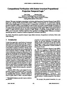
Explicit Invariant Checking. We implemented the explicit invariant checking algorithm as a self-contained Fujaba plug-in. It either pronounces a specification correct or produces a set of counterexamples. Checking just the physical part of the case study yielded the expected collisions, whereas the verification of the complete model proved it to be correct. Figure 10 displays the performance results for the explicit implementation of the SearchCounterexample subroutine. It shows the computation times in seconds for each pair of rule and forbidden graph. The rules are listed on the Xaxis, whereas the invariants are listed on the Y-axis. The number of nodes in R has been used to order the rules and invariants. The slope of the graph supports our hypothesis that the computation time of the algorithm mainly depends on the complexity of the involved graphs. The extreme case
Figure 10: Computation times (in seconds) for explicit search counterexample
Figure 11: Computation times (in seconds) for symbolic search counterexample
Table 2: Run-times for verifying the largest pairs Rule / pattern (nodes:edges) explicit symbolic goDC1(7:10) / invalidDCPattern(5:4) 744 s 11.2 s goDC2(6:09) / invalidDCPattern(5:4) 170 s 6.5 s goDC1(7:10) / noDC(4:4) 20 s 16.8 s goDC2(6:09) / noDC(4:4) 7s 13.1 s goDC1(7:10) / unambigousOn(3:2) 60 s 6.1 s goDC2(6:09) / unambigousOn(3:2) 36 s 2.9 s goDC1(7:10) / unambigousNext(3:2) 48 s 4.1 s goDC2(6:09) / unambigousNext(3:2) 33 s 2.1 s
time of 744 s for the explicit algorithm. This case indicates that the speed-up due to the symbolic encoding can be extremely high for certain hard cases with a high number of nodes and edges.
6.
RELATED WORK
Verifying finite state spaces. Caporuscio et al. propose to build a system with dynamically changing structures by using architectural patterns [8]. To verify such a system, they suggest to consider a certain minimal sub-model and verify it by model checking. The model checking result has to be generalized manually to ensure that it holds for all possible states. In our approach, in contrast, we support a fully-automatic procedure for verifying whether only safe sub-models can be reached at run-time. Alloy allows the design and analysis of systems with changing structures [16]. DynAlloy extends Alloy in such a way that state changes can also be modeled [10]. In contrast to our approach, where operations are described by story patterns, Alloy and DynAlloy require operations and properties given as logical formulae. They check whether the given properties are operational invariants of the system. Varr´ o uses a visual language for modeling systems, and transforms the models then into a model-checker specific input [24]. This approach has been successfully applied to verify service-oriented systems [3]. Instead of transforming a system to a model checker’s input format, Rensink performs the model checking directly on the GTS [21]. As a consequence, his tool implementation GROOVE focuses on pure GTS, rather than on object-oriented models. The tool (and language) Real-Time Maude is based on rewriting logics [20]. The tool supports the simulation of a single behavior of the system as well as model checking of the complete state space, if it is finite. In contrast to our work, the above approaches have two main restrictions. First, they require an initial graph. Second, the application of the methods is only possible if the system to be verified either has a finite state space or the system is abstracted to a finite state model of moderate size. To require a fixed initial graph and a finite state space is not appropriate for mechatronic systems, and the abstraction to a finite state space is (currently) difficult to achieve. However, there is work in progress in this direction (cf. [2]).
resulting from the combination of the goDC1 rule and invalidDCPattern invariant consumed 744s and is omitted from this figure. The explicit algorithm required 34 min for the verification of the overall system. Symbolic Invariant Checking. The symbolic invariant checker was implemented as a Fujaba plug-in that generates the required RML program from the model and passes it to the graph manipulation engine CrocoPat, which is based on a highly optimized BDD package. The prototypical implementation of the symbolic algorithm results in drastically reduced computation times for large pairs. The run-time increases only moderately with increasing size of the patterns, as shown by Fig. 11. The largest rule/invariant pair is verified in 11.2 s. The symbolic algorithm requires only 5 min to complete the overall verification. Summary. Table 2 lists the computation times for the largest rule/invariant pairs. The pairs are ordered according to the size of the forbidden graph patterns. For the explicit algorithm, the combinatoric complexity of the rule/invariant pair, i.e., the number of different ways to intersect the patterns, has the most significant impact on the computation time. This explains why the pair goDC2 and noDC is a particularly easy case for the explicit algorithm, in spite of the size of the pair, as the number of possible intersections is constrained by a large number of positive edges. The symbolic algorithm seems to be dramatically less sensitive to increasing problem complexity of the rules and invariants. The extreme case in the first row in the table, which results from the combination of the goDC1 rule and invalidDCPattern invariant, especially highlights this fact: a run-time of 11.2 s for the symbolic algorithm versus a run-
80
8.
Verifying infinite state spaces. The only approach that explicitly addresses the verification of infinite state systems with changing structure so far is the following. A GTS can be transformed into a finite structure, called Petri graph [1]. Such a Petri graph consists of a graph and a Petri net, each of which can be analyzed with existing tools for the analysis of Petri nets. For infinite systems, the authors suggest an approximation. The approach is not appropriate for the verification of mechatronic systems, because it requires an initial graph and the expressiveness of the underlying GTS is rather restricted, e.g., rules must not delete nodes.
[1] P. Baldan, A. Corradini, and B. K¨ onig. A static analysis technique for graph transformation systems. In Proc. CONCUR, LNCS 2154, pages 381–395. Springer, 2001. [2] P. Baldan, B. K¨ onig, and A. Rensink. Graph grammar verification through abstraction (summary 2). Proc. Dagstuhl Seminar 04241, 2005. [3] L. Baresi, R. Heckel, S. Th¨ one, and D. Varr´ o. Modeling and validation of service-oriented architectures: Application vs. style. In Proc. ESEC/FSE, pages 68–77. ACM, 2003. [4] D. Beyer, A. Noack, and C. Lewerentz. Efficient relational calculation for software analysis. IEEE Trans. on Software Engineering, 31(2):137–149, 2005. [5] R. Bharadwaj and S. Sims. Salsa: Combining constraint solvers with BDDs for automatic invariant checking. In Proc. TACAS, LNCS 1785, pages 378–394. Springer, 2000. [6] D. Bradley, D. Seward, D. Dawson, and S. Burge. Mechatronics. Stanley Thornes, 2000. [7] S. Burmester, H. Giese, and M. Tichy. Model-driven development of reconfigurable mechatronic systems with mechatronic UML. In Model Driven Architecture: Foundations and Applications, LNCS 3599, pages 47–61. Springer, 2005. [8] M. Caporuscio, P. Inverardi, and P. Pelliccione. Formal analysis of architectural patterns. In Proc. EWSA, LNCS 3047, pages 10–24. Springer, 2004. [9] M. Charpentier. Composing invariants. In Proc. FME, LNCS 2805, pages 401–421. Springer, 2003. [10] M. F. Frias, J. P. Galeotti, C. L. Pombo, and N. Aguirre. DynAlloy: Upgrading Alloy with actions. In Proc. ICSE, pages 442–451. ACM, 2005. [11] H. Giese, S. Burmester, W. Sch¨ afer, and O. Oberschelp. Modular design and verification of component-based mechatronic systems with online-reconfiguration. In Proc. FSE, pages 179–188. ACM, 2004. [12] H. Giese and D. Schilling. Towards the automatic verification of inductive invariants for infinite state UML models. Technical Report tr-ri-04-252, University of Paderborn, Germany, 2004. [13] H. Giese, M. Tichy, S. Burmester, W. Sch¨ afer, and S. Flake. Towards the compositional verification of real-time UML designs. In Proc. ESEC/FSE, pages 38–47. ACM, 2003. [14] R. Heckel, J. K¨ uster, and G. Taentzer. Towards automatic translation of UML models into semantic domains. In Proc. AGT, pages 11–22, 2002. [15] R. Heckel and A. Wagner. Ensuring consistency of conditional graph rewriting — a constructive approach. ENTCS, 2, 1995. [16] D. Jackson. Alloy: A lightweight object modelling notation. ACM Trans. Software Engineering and Methodology, 11(2):256–290, 2002. [17] F. Klein and H. Giese. Separation of concerns for mechatronic multi-agent systems through dynamic communities. In SELMAS III, LNCS 3390, pages 272–289. Springer, 2005. [18] H. K¨ ohler, U. Nickel, J. Niere, and A. Z¨ undorf. Integrating UML diagrams for production control systems. In Proc. ICSE, pages 241–251. ACM, 2000. [19] D. Musliner, R. Goldman, M. Pelican, and K. Krebsbach. Self-adaptive software for hard real-time environments. IEEE Intelligent Systems, 14(4), 1999. ¨ [20] P. Olveczky and J. Meseguer. Specification and analysis of real-time systems using Real-Time Maude. In Proc. FASE, LNCS 2984, pages 354–358. Springer, 2004. [21] A. Rensink. Towards model checking graph grammars. In Proc. AVoCS, pages 150–160. University of Southampton, 2003. [22] G. Rozenberg, editor. Handbook of Graph Grammars and Computing by Graph Transformation: Foundations, volume 1. World Scientific Pub Co, 1997. [23] J. Sztipanovits, G. Karsai, and T. Bapty. Self-adaptive software for signal processing. Commun. ACM, 41(5):66–73, 1998. [24] D. Varr´ o. Automated formal verification of visual modeling languages by model checking. Software and System Modeling, 3(2):85–113, 2004.
Verifying invariants. In the context of graph transformations, Heckel and Wagner used the idea of gluing a rule’s RHS with a forbidden graph pattern and then performing a backward application of the rule, to ensure consistency [15]. Using backward application, they transform the forbidden graph patterns into additional negative application conditions (NAC), i.e., negative nodes of the LHS. The transformation of a correct into an incorrect graph is thus prevented by the modified rule. However, the objective of their approach is not to verify the consistency of a set of transformation rules w.r.t. a set of forbidden graph patterns, but rather to automatically construct a set of modified rules that ensures consistency by avoiding the production of forbidden graphs, at the cost of possibly adding vacuous constraints. Applied to our domain as a run-time checking technique, this approach would only work where the extensions respect the agent’s actually accessible context and do not modify physical processes such as the movement of shuttles.
7.
REFERENCES
CONCLUSION
We presented an extension of the Mechatronic UML development approach towards the modeling and verification of mechatronic multi-agent systems. It takes architecturelevel structural adaptation of the agent network at run-time into account. We developed an automated checking technique for structural invariants, based on the formal model of graph transformation systems. System states are modeled as graphs, and system transitions are modeled as graph transformations. Safety properties are modeled as inductive invariants on the graph transformation rules. The performance of our approach is determined by the size of the safety property (given as a set of forbidden graph patterns) and by the size of the transformation rules. The symbolic encoding of the verification procedure enables the application of efficient symbolic graph manipulation engines. Our experiments confirm that the symbolic encoding of our algorithm scales better than the explicit encoding. We recorded a speed-up of more than an order of magnitude for the most complex rule/invariant pair. As expected, both implementations scale vastly better for non-trivial systems than an orthogonal approach that uses state space exploration. Future work in this project includes the improvement of the user-interface to make the interaction between the engineer and the formal model more convenient (e.g., visual counterexample inspection), the evaluation of the approach in an industrial-size case study, and releasing the Fujaba extension as a stable verification product.