Symmetric Surface-Feature based 3D Face Recognition for Partial Data Dirk Smeets, Johannes Keustermans, Jeroen Hermans, Peter Claes, Dirk Vandermeulen, Paul Suetens K.U.Leuven, ESAT-PSI IBBT-K.U.Leuven Future Health Department Medical Imaging Research Center, University Hospitals Gasthuisberg, Herestraat 49 - bus 7003, B-3000 Leuven, Belgium
[email protected]
Abstract
3D face representations. This shift expresses itself in large evaluations of 3D face recognition algorithms. In 2006, the Face Recognition Grand Challenge (FRGC) [10] was the first large comparison, followed by Shape Retrieval Contest (SHREC) in 2007 [13], 2008 [4] and 2011 [14].
Since most 3D cameras cannot capture the complete 3D face, an important challenge in 3D face recognition is the comparison of two 3D facial surfaces with little or no overlap. In this paper, a local feature method is presented to tackle this challenge exploiting the symmetry of the human face. Features are located and described using an extension of SIFT for meshes (meshSIFT). As such, features are localized as extrema in the curvature scale space of the input mesh, and are described by concatenating histograms of shape indices and slant angles of the neighborhood. For 3D face scans with sufficient overlap, the number of matching meshSIFT features is a reliable measure for face recognition purposes. However, as the feature descriptor is not symmetrical, features on one face are not matched with their symmetrical counterpart on another face impeding their feasibility for comparison of face scans with limited or no (left-right) overlap. In order to alleviate this problem, facial symmetry could be used to increase the overlap between two face scans by mirroring one of both faces w.r.t. an arbitrary plane. As this would increase the computational demand, this paper proposes an efficient approach to describe the features of a mirrored face by mirroring the meshSIFT descriptors of the input face. The presented method is validated on the data of the “SHREC ’11: Face Scans” contest, containing many partial scans. This resulted in a recognition rate of 98.6% and a mean average precision of 93.3%, clearly outperforming all other participants in the challenge.
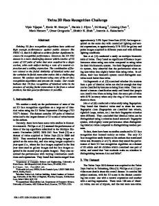
Technological improvements are making 3D surface capturing devices affordable for security purposes promoting 3D face recognition for real case scenarios. However, most 3D scanners only have a limited capture range, impeding the scanning of the entire face. As a result, 3D face recognition is pose dependent. In realistic situations, such as for uncooperative subjects or uncontrolled environments, no assumption can be made on the pose. Therefore, 3D face recognition methods should be able to match partials scans with little or even no overlap. Figure 1 shows examples of partial scans from the SHREC 2011 data [14]. As can be seen, there is only a little overlap between the third and fourth (first in the second row) scan.
1. Introduction Although research in automatic face recognition has been conducted since the 1960’s [2], it is still active. Because of specific difficulties like pose variations and varying lighting conditions, recent research has shifted from 2D to
Figure 1. Examples of partial scans with little overlap (images from the SHREC 2011 data [14]).
1 978-1-4577-1359-0/11/$26.00 ©2011 IEEE
1.1. Related work Most previously proposed 3D face recognition methods assume the entire face to be visible or, at least, have sufficient overlap with other scans. While excellent surveys exist summarizing the extensive work in 3D face recognition [12, 3], we will review the work on face recognition not requiring overlap only. This is, in contrast to 3D face recognition in general, a rather limited field of research. The Morphable Model (MM) is a statistical shape (and texture) model which is originally used to reconstruct 3D faces from 2D photographs [1]. Fitting the 3D shape model (without texture) to a partial 3D scan, however, estimates the most likely 3D face as shown by van Jole and Veltkamp, and by Claes et al. in [14]. The results of both methods clearly differ, indicating the dependence of the implementation. Passalis et al. [7] propose a method based on fitting an Annotated Face Model (AFM) to each partial scan. The pose and occluded areas caused by the pose are detected using an automatic landmark detector. Next, the AFM is fitted to the scan using facial symmetry resulting in a pose invariant geometry image.
1.2. Overview In this paper, we propose an adaptation of the meshSIFT algorithm [6] that makes use of facial symmetry for comparison of two 3D face scans with little or no overlap. In section 2 the meshSIFT algorithm is described, including the detection, description and matching of surface features. Next the adaptations that allow comparison of non overlapping surface scans using facial symmetry are presented in section 3. The most simple, but computational demanding adaptation is to mirror the 3D face w.r.t an arbitrary plane and then applying the meshSIFT algorithm on the new surface. The main contribution of this paper is the symmetric local feature descriptor, which only has a small extra computational demand. The results of the different methods are then shown in section 4 and discussed in section 5. At the end, we draw some conclusions.
mesh with a binomial filter. Figure 2 shows three smoothed meshes of the constructed scale space.
Figure 2. Smoothed meshes in the scale space (images from Bosphorus database [11]).
Next, for the detection of salient points in the scale space, the mean curvature H is computed for each vertex and at each scale in the scale space (Hi ). Note that the mesh itself is smoothed and not the function on the mesh (H). Extrema (minima and maxima) in scale spaces of differences between subsequent scales (dHi = Hi+1 − Hi ) are selected as local feature locations. Finally, the correct scale, which corresponds with some amount of smoothing, is assigned to each scale space extremum, leading to a keypoint with an assigned scale.
2.2. Orientation assignment In order to obtain an orientation-invariant descriptor, each keypoint is assigned a canonical orientation. By expressing the neighborhood size in function of the scale, we ensure a scale invariant descriptor as well. First, for each vertex within this region, the normal vector is computed (using [8]) and the geodesic distance to the respective keypoint (using [9]) is determined. Next, as shown in figure 3, all calculated normal vectors are projected onto the tangent plane to the mesh containing the keypoint.
2. MeshSIFT The meshSIFT algorithm [6] consists of four major components: keypoint detection, orientation assignment, the local feature description and feature matching.
2.1. Keypoint detection This component identifies salient points on the mesh. Similar to the SIFT algorithm [5] a scale space is constructed containing smoothed versions of the input mesh. These smoothed versions are obtained by approximating a Gaussian filter for meshes as subsequent convolutions of the
Figure 3. The neighborhood of a scale space extremum with normals and projected normals
These projected normal vectors are gathered in a weighted histogram comprising 360 bins. Each histogram entry is Gaussian weighted with its geodesic distance to the keypoint. The resulting histogram is smoothed by convolving it three times with a Gaussian filter for a more accurate and robust localization of the canonical orientation. Finally,
the highest peak in the histogram and every peak above 80% of this highest peak value is selected as a canonical orientation. If more than one canonical orientation exists for a keypoint, this results in multiple keypoints, each assigned one of the canonical orientations.
2.3. Feature description The local descriptor provides for each keypoint (with assigned scale and canonical orientation) a feature vector consisting of concatenated histograms. Each of these histograms is calculated over a small circular region, as shown ˆ S and p ˆ θ , with in figure 4. In each region two histograms, p
3. Symmetric meshSIFT In order to allow comparison of face scans with limited or no overlap, such as the scans in figure 1, the meshSIFT algorithm is adapted. As the feature descriptor is not symmetrical, features on one face are not matched with their symmetrical counterpart. As a result, no matching features are found between scans with no overlap. The relevant symmetry here is reflection symmetry because of the left-right symmetry in human faces. The adaptation will, however, also improve recognition when other reflection symmetries are present in the 3D objects.
3.1. 3D face mirroring In order to alleviate this problem, facial bisymmetry is used to increase the overlap between two face scans by mirroring one of both faces w.r.t. an arbitrary plane. After mirroring the face, the normals on the surface are reoriented and the meshSIFT algorithm is applied to the new surface providing a new set of feature descriptors. The feature descriptors of the mirrored face (F = {f1m , f2m , . . . fnm }) are finally added to the feature descriptors of the original face (F = {f1 , f2 , . . . fn }) into one big feature set.
Figure 4. Location and order of the regions w.r.t. the canonical orientation, used for the construction of the feature vector.
8 bins each are computed. The first contains the shape index, which is a combination of minimum and maximum curvature. The second contains the slant angles, which are defined as the angle between every projected normal and the canonical orientation. First, each entry for both histograms is Gaussian weighted with the geodesic distance to the keypoint and with the geodesic distance to the center of the region. Next, every histogram is normalized and clipped, reducing the influence of large histogram values. Finally, the histograms are concatenated in one feature vecˆ θ,1 . . . p ˆ S,9 p ˆ θ,9 ]T . tor fi = [ˆ pS,1 p
2.4. Feature matching In order to find corresponding features, two sets of feature vectors are compared using the angle as similarity measure. The angle is defined as the arccosine of the dotproduct of two feature vectors, normalized for their magnitude. The angles of all candidates are then ranked in ascending order. If the ratio between the first and the second is smaller than 0.7, a match is accepted; other matches are rejected. Matches are mostly found between two face surfaces of the same person, allowing the algorithm to be used for 3D face recognition [6]. The number of matches is simply used as similarity criterion.
3.2. Symmetric feature descriptor As mirroring the faces would increase the computational demand, this paper also proposes an efficient approach to describe the features of a mirrored face by mirroring the meshSIFT descriptors of the input face. We will call this method ‘symmetric meshSIFT’. The major part of the algorithm is identical to the standard meshSIFT, including the feature detection (see sect. 2.1), orientation assignment (sect. 2.2), feature description (sect. 2.3) and feature matching (sect. 2.4). However, an extra step, extending the feature list using facial symmetry, is added between feature description and feature matching. Given a feature list F m = {f1 , f2 , . . . fn }, each feature fi is transformed to its symmetrical equivalent fis , defined as
fis
=
ˆ sθ,1 p ˆ S,2 p ˆ sθ,2 p ˆ S,9 p ˆ sθ,9 [ˆ pS,1 p ˆ S,8 p ˆ sθ,8 p ˆ S,7 p ˆ sθ,7 p ˆ S,6 p ˆ sθ,6 p ˆ S,5 p ˆ sθ,5 p ˆ S,4 p ˆ sθ,4 p ˆ S,3 p ˆ sθ,3 ]T , p
(1)
ˆ S,i the histogram of shape indices in region i and the with p ˆ sθ,i the symmetrized histogram of slant angles in region i. p This symmetrization is performed by flipping the histogram vector. Figure 5 clarifies the permutation of the different regions in which the histograms are computed. Finally each face is described by a feature list F = {f1 , f1s , f2 , f2s , . . . fn , fns , }.
Table 1. Results of the different methods method meshSIFT mirroring+meshSIFT symmetric meshSIFT
1st Tier 62.43% 88.21% 88.31%
2nd Tier 65.36% 95.10% 95.33%
MAP 65.19% 93.28% 93.26%
Figure 5. Changing of the order of regions (as defined in figure 4) to symmetrize the feature vector.
4. Results To demonstrate the effectiveness of the proposed methods, we performed the validation experiment of the “SHREC ’11 - SHape REtrieval Contest for 3D Face Scans” [14], which has the objective to evaluate the performance of different 3D face recognition techniques. The dataset used contains scans from an anthropological collection of 130, approximately 100 year old masks. The dataset is divided in a training set of 60 high quality scans, a test set of 70 high quality and 580 low quality scans and a query set of 70 low quality scans1 . The low quality scans have a lower resolution and contain only a part of the face (partial data), such as the scan in figure 1. For each method, a ranked list per query image is composed containing the 650 test images ordered according to a decreasing number of feature matches with the query image. Several evaluation measures can then provide an idea of the performance of each method. The recognition rate (RR) is the frequency that the highest rank (most matching features) is from the same class. The first and second tier recall are the fractions of faces from the correct class among the first n and the first 2n, respectively, where n is the class size of a specific object. We call the recall the mean of the first and second tier recall. The average precision (per query) is the average of the precision scores after each relevant item (same identity) in the list, with precision defined as the number of relevant items over the scope. The mean average precision (MAP) is the mean of the average precision over all queries. The mean average dynamic precision (MADP) is defined as the average sum of precision with increasing scope, averaged out over all queries2 . 1 The dataset is publicly available at http://give-lab.cs.uu. nl/SHREC/shrec2011/faces/index.php 2 More information on the used evaluation measures can be found on
MADP 23.04% 86.24% 86.14%
RR 97.14% 98.57% 98.57%
EER 20.37% 3.34% 3.59%
[email protected]%FAR 56.42% 78.06% 78.60%
The receiving operating characteristic (ROC) curve is an excellent performance descriptor for verification and plots the false rejection rate (FRR) versus the false acceptance rate (FAR). The equal error rate (EER) is the point on the ROC for which the FAR is equal to the FRR and can therefore be seen as an important characteristic for the verification performance. Another, often mentioned, point on the ROC is the verifcation rate (VR = 1-FRR) at 0.1% FAR. The results of the different methods (meshSIFT, meshSIFT after mirroring the face and symmetric meshSIFT) are summarized in table 1. These results demonstrate that using facial symmetry for recognition clearly improves the performance. For the recognition rate this increase is less pronounced since it only considers the best match for each query which mostly is a full face scan. Matching a test scan with limited of no overlap with the query scan won’t yield many matches, causing the test scan to have a low rank. By using facial symmetry, many matches are found, improving the rank. This positively influences the recall, MAP and MADP. Also the threshold on the number of matches to determine whether a person is genuine or an imposter, can be defined more reliably as indicated by the EER and
[email protected]%FAR. The difference in performance between the symmetric meshSIFT and meshSIFT after mirroring the 3D face is really small demonstrating that transforming the descriptor is as precise as, but more efficient than transforming (mirroring) the 3D face.
5. Discussion The validation results demonstrate the accuracy of the symmetric meshSIFT and meshSIFT after mirroring the 3D face recognition for partial data. The symmetric meshSIFT only has a small extra computational cost for matching the symmetrized features. Applying meshSIFT after mirroring also has this extra feature matching cost. Moreover, the computational demands for feature detection and description double since features are detected and described on the double amount of 3D scans. Performance evaluation on a standard dataset allows comparison with other 3D face recognition methods. Table 2 shows this comparison with all participants of the official SHREC 2011 contest [14]. The results are sorted in decreasing order of the mean average precision (MAP) (since this measure also considers the lower ranks). http://give-lab.cs.uu.nl/SHREC/shrec2008/
Table 2. The results the different methods compared with the 3D face recognition methods from the other participants in “SHREC ’11: Face Scans” [14] method mirroring+meshSIFT symmetric meshSIFT Robust PCA fit (run 1) meshSIFT Robust PCA fit (run 2) Salient points (run 3) Salient points (run 2) Salient points (run 1) Salient points (run 4) Radial curves (run 2) Radial curves (run 4) Radial curves (run 5) Radial curves (run 1) Radial curves (run 3) Morphable model (run 1) Morphable model (run 2)
recall 91.65% 91.82% 68.37% 63.89% 61.23% 47.81% 45.73% 39.63% 40.19% 24.24% 22.00% 21.86% 20.46% 20.95% 19.67% 19.48%
MAP 93.28% 93.26% 70.29% 65.19% 61.90% 47.58% 45.36% 40.19% 39.57% 24.77% 22.24% 22.12% 21.11% 21.02% 19.08% 18.24%
RR 98.57% 98.57% 88.57% 97.14% 80.00% 92.86% 90.00% 85.71% 85.71% 44.29% 41.43% 41.43% 41.43% 31.43% 41.43% 38.57%
Table 2 demonstrates that the proposed feature-based method for 3D face recognition using facial symmetry clearly outperforms all other methods presented at “SHREC’11: Face Scans”. The recall as well as the mean average precision are more than 20% higher than the second best performing method (robust PCA fit, run 1), which fits a PCA shape model (morphable model) to a face scan in a robust way (using outlier estimation). Face comparison is done using the Mahalanobis cosine between the fitting coefficients as similarity measure. This method can also handle partial data, since each partial scan is completed by fitting the statistical model. Partial scans, however, can still lead to overfitting. A major drawback of the PCA method is that it requires a robust registration, which is performed using a feature-based approach, and outlier robust fitting to the partial scan. Failures in the fitting process will cause performance drops for recognition. Another disadvantage over the proposed feature-based methods is the need for representative training data. The method based on salient points (run3) is also a local feature method that, however, does not take the facial symmetry into account. Therefore, it provides good recognition rates and poorer recalls and mean average precision, similar to the performance behaviour of meshSIFT. All other methods perform insufficient w.r.t. all evaluation measures. Comparing symmetric meshSIFT with the AFM method of Passalis et al. [7] is more difficult since different datasets are used. However, the AFM method also requires a robust registration and fitting. The registration is done by automatic landmark detection, which regularly fails for large pose variations (table 1 in [7]).
6. Conclusion In this paper, we have proposed a surface feature method that uses the intrinsic bilateral symmetry in the human face to enlarge the set of feature descriptors, without the need of (local) registration. The augmentation of the feature
set is essential when a left face scan is compared with a right one, or vice versa. However, for limited or no overlap in directions different to the bilateral symmetry, performance is not improved. Validation demonstrates that the proposed method outperforms all other methods validated on the “SHREC’11: Face Scans” dataset with at least 20% (regarding the mean average precision). As future work, we plan to validate the method on the UHDB7 Database3 , which can be considered as another reference dataset for matching partial data.
References [1] V. Blanz and T. Vetter. A morphable model for the synthesis of 3D faces. In SIGGRAPH, pages 187–194, 1999. 2 [2] W. W. Bledsoe. The model method in facial recognition. Technical Report PRI 15, Panoramic Research, Inc., Palo Alto, California., 1964. 1 [3] K. W. Bowyer, K. I. Chang, and P. J. Flynn. A survey of approaches and challenges in 3D and multi-modal 3D + 2D face recognition. Computer Vision and Image Understanding, 101(1):1–15, 2006. 2 [4] M. Daoudi, F. ter Haar, and R. C. Veltkamp. SHREC 2008 - shape retrieval contest of 3D face scans. http://give-lab.cs.uu.nl/SHREC/ shrec2008/, 2008. 1 [5] D. G. Lowe. Distinctive image features from scaleinvariant keypoints. International Journal of Computer Vision, 60(2):91–110, 2004. 2 [6] C. Maes, T. Fabry, J. Keustermans, D. Smeets, P. Suetens, and D. Vandermeulen. Feature detection on 3D face surfaces for pose normalisation and recognition. In BTAS ’10, 2010. 2, 3 [7] G. Passalis, P. Perakis, T. Theoharis, and I. A. Kakadiaris. Using facial symmetry to handle pose variations in Real-World 3D face recognition. IEEE Transactions on Pattern Analysis and Machine Intelligence, 99(PrePrints), 2011. 2, 5 [8] G. Peyre. Toolbox graph. MATLAB Central File Exchange Select, 2009. 2 [9] G. Peyre. Toolbox mast marching. MATLAB Central File Exchange Select, 2009. 2 [10] P. J. Phillips, P. J. Flynn, T. Scruggs, K. W. Bowyer, J. Chang, K. Hoffman, J. Marques, J. Min, and W. Worek. Overview of the face recognition grand challenge. In CVPR ’05, volume 1, pages 947–954, 2005. 1 [11] A. Savran, N. Alyuz, H. Dibeklioglu, O. Celiktutan, B. G¨okberk, B. Sankur, and L. Akarun. Bosphorus 3 http://cbl.uh.edu/URxD/datasets/
database for 3D face analysis. In COST 2101 - BIOD, 2008. 2 [12] A. Scheenstra, A. Ruifrok, and R. C. Veltkamp. A survey of 3D face recognition methods. In AVBPA ’05, volume 3546, pages 891–899, 2005. 2 [13] R. C. Veltkamp and F. ter Haar. SHREC 2007 - shape retrieval contest of 3D face models. http://give-lab.cs.uu.nl/SHREC/ shrec2007/, 2007. 1 [14] R. C. Veltkamp, S. van Jole, B. Ben Amor, M. Daoudi, H. Li, L. Chen, P. Claes, D. Smeets, J. Hermans, D. Vandermeulen, and P. Suetens. SHREC’11: 3D face models retrieval. In 3D OR ’11, pages 89–95, 2011. 1, 2, 4, 5