Jun 4, 2013 - Phase difference θ2 â θ1 for the pairs of SB solutions - dashed red line; intensity difference I1 â I2 - solid blue line. Thicker lines mark stable ...
Symmetry breaking in binary chain with nonlinear sites Dmitrii N. Maksimov and Almas F. Sadreev
arXiv:1306.0700v1 [nlin.CD] 4 Jun 2013
Institute of Physics, 660036, Krasnoyarsk, Russia (Dated: June 5, 2013) We consider a system of two or four nonlinear sites coupled with binary chain waveguides. When a monochromatic wave is injected into the first (symmetric) propagation channel the presence of cubic nonlinearity can lead to symmetry breaking giving rise to emission of antisymmetric wave into the second (antisymmetric) propagation channel of the waveguides. We found that in the case of nonlinear plaquette there is a domain in the parameter space where neither symmetry preserving nor symmetry breaking stable stationary solutions exit. As a result injection of a monochromatic symmetric wave gives rise to emission of nonsymmetric satellite waves with energies different from the energy of the incident wave. Thus, the response exhibits nonmonochromatic behavior. PACS numbers: 03.75.-b,05.45-a,42.65.Ky,42.65.Pc,42
I.
INTRODUCTION
To the best our knowledge symmetry breaking (SB) in the nonlinear systems was first predicted by Akhmediev who considered a composite structure of a single linear layer between two symmetrically positioned nonlinear layers [1]. One could easily see that if the wave length is larger than the thickness of the nonlinear layers then Akhmediev’s model could be reduced to a dimer governed by the nonlinear Shr¨odinger equation. Independently the SB was discovered for the discrete nonlinear Schr¨odinger equation with a finite number of coupled cites (nonlinear dimer, trimer, etc) [2–8]. For example, in the case of the nonlinear Schr¨odinger dimer Eilbeck et al found two different families of stationary solutions [2]. The first family is symmetric (antisymmetric) (|φ1 | = |φ2 |) while the second is nonsymmetric (|φ1 | 6= |φ2 |). This consideration was later extended to a nonlinear dimer embedded into an infinite linear chain [9] with the same scenario for the SB. Multiple bifurcations to the symmetry breaking solutions were demonstrated by Wang et al [10] for the nonlinear Schr¨odinger equation with a square four-well potential. Remarkably, the above system can also support a stable state with a nodal point, i.e., quantum vortex [11]. In the framework of the nonlinear Schr¨odinger equation one can achieve bifurcation to the states with broken symmetry varying the chemical potential which is equivalent to the variation of the population of the nonlinear sites or, analogously, of the constant in the nonlinear term of the Hamiltonian. In practice, however, one would resort to the optical counterparts of the quantum nonlinear systems where the variation of the amplitude of the injected wave affects the strength of Kerr nonlinearity (see Refs. [12–22] for optical examples of the SB). In the present paper we consider a nonlinear dimer and a square four-site nonlinear plaquette coupled with two channel waveguides in the form of binary tight-binding chains. The latter system is analogous to that recently considered in Ref. [23] where the plaquette however was set up without mirror symmetry with respect to the centerline of the waveguide. Due to nonlinearity of the plaquette the system can spontaneously bifurcate between diodeantidiode and bidirectional transmission regimes. In our case, we will show that when a monochromatic wave is injected into the first (symmetric) propagation channel the presence of the cubic nonlinearity can lead to symmetry breaking giving rise to emission of antisymmetric wave into the second (antisymmetric) propagation channel of the waveguides. This result raises an important question about the effect of a probing wave on the SB. To allow for symmetry breaking the architecture of the open system should support some symmetries of its closed counterpart. When the growth of the injected power can result in bifurcations into the states violating the symmetry of the probing wave by the amplitude of the scattering function [12–14, 17, 18, 20, 21, 24] or by its phase [25]. The second important question is whether the solutions in the linear waveguides could be stationary monochromatic plane waves, reflected ψ(n, t) = R exp(−ikn − iE(k)t) and transmitted ψ(n, t) = T exp(ikn − iE(k)t), where R and T are the reflection and transmission amplitudes. If the answer is positive then we can apply the Feshbach projection technique [26–30] and implement the formalism of non-Hermitian effective Hamiltonian (now nonlinear) which acts on the nonlinear sites only thus truncating the Hilbert space to the scattering region [21, 30]. When the radiation shifts of the energy levels are neglected that formalism reduces to the well known coupled mode theory (CMT) equations [31–34]. In the present paper we will show that there are domains in the parameter space where there are no stable stationary solutions. We will demonstrate numerically that a plane wave incident onto a nonlinear object gives rise to emission of multiple satellite waves with energies (frequencies) different from the energy (frequency) of the probing wave.
2 II.
STRUCTURE LAY-OUT AND BASIC EQUATIONS
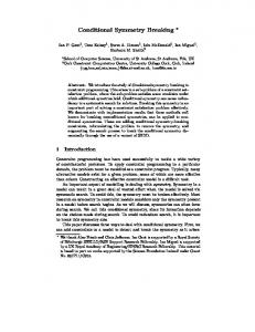
We consider two tight-binding structures shown in Fig. 1, nonlinear dimer (a) and nonlinear four-site square plaquette (b) coupled with linear binary chains. Each chain, left and right, supports two continua of plane waves � � � � 1 1 1 1 (±) (±) exp(±ik1 n − iE(k1 )t), ψ2 (n, t) = p exp(±ik2 n − iE(k2 )t) (1) ψ1 (n, t) = p 2| sin k1 | 1 2| sin k2 | −1
where indices p = 1, 2 enumerate continua or channels with the propagation bands given by E(kp ) = −2 cos kp ∓ 1, −π ≤ kp ≤ π.
(2)
In order to control the resonant transmission we adjust the hopping matrix element between the nonlinear sites and waveguides ǫ < 1 [30] shown in Fig. 1 by dash lines. The coupling between nonlinear sites (shown in Fig. 1 by dash-dot line) is controlled by constant γ.
u0
u−2 u −1 ε ε
γ
v−2 v−1
v0
u−2 u−1 u0 ε ε
γ
v−2 v−1
v0
u1
u2
v1
v2
(a)
ε ε
u1 γ γ γ v1
(b)
u2
u3
v2
v3
ε ε
FIG. 1: (a) Two-channel waveguide in form of binary tight-binding chain which holds a nonlinear dimer (shown by filled circles). (b) The same as in subplot (a) but with four nonlinear sites (four-site plaquette). Green dotted box is placed around the nonlinear scattering region.
In the case of the nonlinear dimer the Schr¨odinger equation takes the following form iu˙ n = −Jn un+1 − Jn−1 un−1 − Kn vn + λδn,0 |un |2 un ,
iv˙ n = −Jn vn+1 − Jn−1 vn−1 − Kn un + λδn,0 |vn |2 vn ,
(3)
where Jn = 1 + (ǫ − 1)(δn,−1 + δn,0 ), Kn = 1 + (γ − 1)δn,0 . In the case of nonlinear square plaquette the Shcr¨ odinger equation could be written down essentially in the same way.
3
(a)
3
0.8
I1−I2, θ1−θ2
transmission
1
0.6 0.4
(b)
2 1 0 −1 −2
0.2
−3 0 −1
−0.5
0
0.5
E
1
0.1
0.2
0.3
E
0.4
0.5
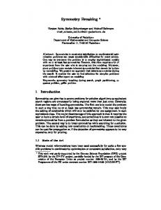
FIG. 2: (Color online) Response of nonlinear dimer to symmetric probing wave. (a) Transmission probability |T11 |2 for symmetry preserving solution - blue dash line, |T11 |2 for SB solutions - solid red line, |T12 |2 SB solutions - solid black. (b) Phase difference θ2 − θ1 for the pairs of SB solutions - dashed red line; intensity difference I1 − I2 - solid blue line. Thicker lines mark stable solutions. The parameters: ǫ = 0.2, A0 = 1, λ = 0.025, γ = 0.
III.
NONLINEAR DIMER
First, let us follow Refs.[35–41] and search for the solution of the Schr¨odinger equation (3) in the form of a stationary wave un (t) = un e−iEt , vn (t) = vn e−iEt
(4)
where the discrete space variable n and the time t are separated. The absence of nonlinearity in the waveguides drastically simplifies analysis of Eq. (3). Assuming that a symmetric/antisymetric wave is incident from the left we can write the solutions in the left ψL (n, t) and right ψR (n, t) waveguides as: (−)
(−)
ψL (n, t) = A0 ψp(+) (n, t) + Rp,1 ψ1 (n, t) + Rp,2 ψ2 (n, t), (+)
(+)
ψR (n, t) = Tp,1 ψ1 (n, t) + Tp,2 ψ2 (n, t),
(5)
where parameter A0 is introduced to tune the intensity of the probing wave. Notice that Eq. (5) implicitly defines reflection and transmission amplitudes Rp,p′ and Tp,p′ with the first subscript p indexing the channels and respectively the symmetriy of the incident wave. One can now match the solutions Eq. (5) to the equations for the nonlinear sites to obtain a set of nonlinear equations for on-site and reflection/transmission amplitudes. Computationally, however, it is more convenient to use the approach of the non-hermitian Hamiltonian [28, 30] in which the number of unknown variables equals to the number of nonlinear sites. Following Ref. [21] we write the equation for the amplitudes on the nonlinear sites (E − Hef f )|ψi = A0 ǫ|ini
(6)
where Hef f = H0 −
X C
VC†
1 VC = E + i0 − HC
�
−ǫ2 (eik1 + eik2 ) + λ|u0 |2 −γ − ǫ2 (eik1 − eik2 ) ǫ2 (eik1 + eik2 ) + λ|v0 |2 −γ − ǫ2 (eik1 − eik2 )
�
.
(7)
Here vector hψ| = (u0 , v0 ) is the state vector of the dimer, H0 is the nonlinear Hamiltonian of the dimer decoupled from the waveguides, VC is the coupling operator [30] between the nonlinear sites and the left and right waveguides C = L, R with the Hamiltonian HC , and hin| = (1, ±1) is the source term for symmetric/antisymmetric incident waves correspondingly. One can easily see that in the limit ǫ → 0 the dimer is decoupled from the waveguides and Eq. (6) limits to the standard nonlinear Schr¨odiner equation of the closed nonlinear dimer. After Eq. (6) is solved one easily obtains transmission/reflection amplitudes from Eq. (3). In Fig. 2 we present the response of the nonlinear dimer to a symmetric probing wave both in form of transmission probabilities |T11 (E)|2 , |T12 (E)|2 Fig. 2(a), and phase θ2 − θ1 and intensity I1 − I2 differences Fig. 2(b). On-site
4 4
(a)
0.8
I1−I2, θ1−θ2
transmission
1
0.6 0.4 0.2 0 −1
−0.5
0
0.5
E
2
0
−2
−4
1
(b)
0.2
0.3
E
0.4
0.5
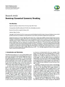
FIG. 3: (Color online) Response of nonlinear dimer to antisymmetric probing wave. (a) Transmission probability |T22 |2 for the symmetry preserving solution - blue dash line; |T22 |2 for SB solutions - solid red line, |T21 |2 SB solutions - solid black line. (b) Phase difference θ2 − θ1 for the pairs of SB solutions - dashed red lines, intensity difference I1 − I2 - solid blue lines. Thicker lines mark stable solutions. The parameters: ǫ = 0.2, A0 = 1, λ = 0.03, γ = 0.
√ √ phases and intensities are defined through u0 = I1 eiθ1 , v0 = I2 eiθ2 . There are two principally different families of solutions similar to those obtained in Ref. [21]. The symmetry preserving family inherits the features of the linear case in which a symmetric probing wave excites only symmetric mode φs = √12 (1, 1) with eigenvalue Es = −γ. In fact, we see a typical example of nonlinear transmission through a resonant state. The transmission probability |T11 (E)|2 for the symmetry preserving family of solutions with I1 = I2 , θ1 = θ2 are shown in Fig. 2 (a) by blue dashed lines. The energy behavior of the transmission is very similar to the case of a linear waveguide coupled with one nonlinear in-channel site [35, 36, 42]. However, one can see that the peak of the resonant transmission is now unstable which is a key to mode conversion as it will be shown below. The stability of the solutions was examined by standard methods based on small perturbations technique (see, for example, Refs. [43, 44]). The SB occurs due to excitation of the second (antisymmetric) mode of the dimer φa = √12 (1, −1) with eigenvalue Ea = γ. The phase and intensity differences for the SB solutions are shown in Fig. 2(b). One can see that the symmetry is broken simultaneously by both intensity I1 6= I2 and phase θ1 6= θ2 of the wave function. This scenario of SB differs from the case of the closed dimer [2, 3, 5] or the dimer opened to a single chain (off-channel architecture) [21] where the symmetry was broken either by the intensities or by the phases of the on-site amplitudes. In Fig. 3 we show the case when the antisymmetric wave is injected to the system. Although the energy behavior of the on-site intensities, on-site phases, and the transmission probabilities to the first and second channels |T21 |2 , |T22 |2 is similar to the case of symmetric probing wave, the stability pattern of the symmetry preserving solution is now typical for the nonlinear transmission through a single nonlinear site Ref. [42]. Finally, following Ref. [45] we present the plots output vs. input, i.e., transmission probabilities |Tp,p′ |2 vs. A20 for both symmetric and antisymmetric probing waves. In Fig. 4 one can see that the input-output curves for the symmetry preserving family of solutions have typical bifurcation behavior while the symmetry breaking family exists only within a bounded domain of the input. As was mentioned above the SB phenomenon results in the mode conversion, i.e., emission of scattered waves into a different channel. Let us consider time evolution of the wave front given by (+)
|ψin (n)i = f (n)ψ1 (n, 0),
(8)
where f (n) =
�
1 e
−(n+100)2 /250
if n ≤ −100 ; if n > −100,
(9)
is an auxiliary function that provides a smooth increase of incident plane wave amplitude. As the wave front propagates (+) to the right the input signal converges to ψ1 (n, t) so one could expect that in course of time the system would stabilize in one of the solutions shown in Fig. 2. In order to perform numerical computations we directly applied both standard forth order Runge-Kutta method and the Besse-Crank-Nicolson relaxation scheme [46] to Eq. (3) with both techniques yielding the same result (Crank-Nicolson approach being slightly advantageous in terms of computational time). The
5 1.4 1.2
2
(a)
1.5
output
1
output
(b)
0.8 0.6 0.4
1
0.5
0.2 0 0
5
10
input
0 0
15
5
10
input
FIG. 4: (Color online) Input A20 vs. outputs |Tp,p′ |2 for nonlinear dimer. (a) Symmetric probing wave hin| = (1, 1), |T11 |2 blue dash line symmetry preserving solutions, |T11 |2 SB solutions - solid red line, |T12 |2 SB solutions - solid black line. (b) Antisymmetric probing wave hin| = (1, −1), |T22 |2 - blue dash line symmetry preserving solutions, |T22 |2 SB solutions - solid red line, |T21 |2 SB solutions - solid black. The parameters: ǫ = 0.2, E = 0.45, λ = 0.025, γ = 0.
25
(a)
2
20
1.5
15
As,Aa
As,Aa
2.5
1 0.5 0 0
(b)
10 5
200
time
400
600
0 0
200
time
400
600
FIG. 5: (Color online) Time evolution of populations As - dashed blue line, Aa - solid red line. ǫ = 0.2, A = 1, λ = 0.025, γ = 0. (a) Stable symmetry preserving solution E = 0.35 (red circle in Fig. 2(a)). (b) Unstable symmetry preserving solution E = 0.25 (red star in Fig. 1(a)). The parameters: ǫ = 0.2, A0 = 1, λ = 0.025, γ = 0
absorbing boundary conditions were enforced at far ends of the waveguides according to Ref. [47] to truncate the problem to a finite domain. Let us first choose the energy in the domain where the symmetry preserving solution is stable, for example E = 0.35 (shown in Fig. 2(a) by red circle). To detect the SB we use the populations As and Aa of the symmetric φs and antisymmetric φa modes correspondingly. Fig. 5(a) shows that although stable SB solutions exit at E = 0.35 the response to the probing signal Eq. (8) contains only symmetric contribution and after several oscillations converges to the stationary transmission. On the other hand, if one chooses the energy of the incident wave from the domain where the symmetry preserving solutions are unstable E = 0.25 (shown in Fig. 2(a) by red star), the system first stabilizes in an unstable symmetry preserving solution but then, due to accumulation of numerical round-off error, it is forced to leave the unstable equilibrium and occupy one of the stable states with broken symmetry Fig. 3(a). Thus, the round-off error induces the SB playing the role of noise in a real experiment. It is important to notice that the results in Fig. 5 agree with the date obtained with the use of the effective non-Hermitian Hamiltonian Eq. (6).
6 1.5
(a)
(b)
0.8
output
transmissions
1
0.6 0.4
1
0.5 0.2 0 −1
−0.5
0
E
0.5
1
0 0
1
2
input
3
4
FIG. 6: (Color online) Response of nonlinear plaquette to symmetric probing wave ǫ = 0.4, γ = 1, λ = 0.09, transmission probability |T11 |2 for symmetry preserving solutions - dashed blue line, |T11 |2 SB solutions - solid red line, |T12 |2 SB solutions - solid black. (a) Transmissions vs. energy, A = 1. (b) Transmissions vs. A2 , E = 0.35. Thicker lines mark stable solutions. In both cases one can see windows were neither symmetry preserving nor symmetry breaking stable solutions exist.
IV.
FOUR-SITE NONLINEAR PLAQUETTE
In the previous section we demonstrated how the phenomenon of SB occurs in the nonlinear dimer due to resonant excitation of both symmetric and antisymmetric modes φs , φa . Notice that a necessary condition for the SB is that both modes be near degenerate to be excited at the same energy. This forced us to chose the inner coupling constant γ = 0. In fact, our numerical tests show that the SB will quickly vanish as γ increased. In that sense the set-up of four-site plaquette seems more feasible because now the closed system supports two degenerate modes of different symmetries at any value of γ, namely hχs | = 21 (1, 1, −1, −1) and hχa | = 12 (1, −1, 1, −1). The corresponding degenerate eigenvalue is Es,a = 0. In the case of the four-site plaquette the effective Hamiltonian takes the following form [28, 30] 2 ik −γ 0 −γ − ǫ2 (eik1 − eik2 )/2 −ǫ (e 1 + eik2 )/2 + λ|u0 |2 2 ik1 ik2 2 −γ − ǫ2 (eik1 − eik2 )/2 −ǫ (e + e )/2 + λ|v | 0 −γ 0 Hef f = −γ − ǫ2 (eik1 − eik2 )/2 −γ 0 −ǫ2 (eik1 + eik2 )/2 + λ|u1 |2 ik2 2 ik1 −ǫ2 (eik1 + eik2 )/2 + λ|v1 |2 0 −γ −γ − ǫ (e − e )/2 (10) Eq. (6) should now be solved for the state vector of the plaquette hψ| = (u0 , v0 , u1 , v1 ) (see Fig. 1(b)) with the source term hin| = (1, ±1, 0, 0). The results of numerical solution are presented in Fig. 6. Although the result is similar to the case of nonlinear dimer (Figs. 2 and 3) there is one important difference. Namely, there is now a domain the parameter space where all stationary solutions are unstable as shown in Figs. 6. Respectively, the solution of the transmission problem in such system can be described neither by transmission and reflection amplitudes Eqs. (5) nor by the Feshbach projection method, i.e. by the the effective non-Hermitian Hamiltonian Eq. (6). The problem of plane wave scattering from the nonlinear plaquette can only be solved through numerical simulation of the time-dependent equation. To perform numerical tests we repeated the wave-front simulations explained in the previous section. Fig. 7 shows the time evolution of populations As , Aa of symmetric and antysimmetric resonant modes |χs i, |χa i. At t = 0 a symmetric wave front (8) is sent from the left waveguide towards the plaquette with its energy and amplitude within the domain of unstable stationary solutions E = 0.4 (shown by red star in Fig 6(a)). First when t ∈ [150, 350] only symmetric state of the plaquette is excited; Aa = 0. However, the symmetry preserving solution is unstable. That causes transition to the symmetry breaking solution Aa > 0 at t ≈ 400. As a result the plaquette emits stationary plane waves of both symmetries with the same energy as the probing wave when t ∈ [450, 650]. Since this solution is also unstable the system transits to another regime at t ≈ 700. It is clearly seen in Fig. 7 that in this regime the solution is also symmetry breaking, however, what is more interesting, it is non-stationary. The Fourier power spectrum F (E) Fig. 8 of the amplitude u3 (see Fig. 1) for t ≥ 800 clearly shows the presence of three peaks, the central peak with energy E = 0.4 and two satellites with energies E1 = −1.71, E2 = 2.51. With the growth of the nonlinearity constant λ which is equivalent to growth of the amplitude of the injected wave the dynamical properties of the nonlinear plaquette change drastically. Fig. 9(a) shows the transmission probabilities
.
7 1
1
0
0
1
As, Aa
15 10
−1 200
0
−1 600
250
650
−1 900
950
5 0 0
200
400
600
800
time
1000
1200
FIG. 7: (Color online) Time evolution of populations of symmetric Bs (blue line), and antisymmetric Ba (red line) resonant modes, ǫ = 0.4, γ = 1, λ = 0.09E = 0.4. The insets show the real parts of amplitudes u3 (blue line), and v3 (red line) vs. time t in the corresponding regimes. One can clearly see that in course of time the system evolves to a non-stationary solution. 5
log10(F(E))
4 3 2 1 0 −1 −2 −3
−2
0
E
2
FIG. 8: (Color online) Logarithmic plot of Fourier power spectrum of output amplitude u3 in the non-stationary regime Fig. 7.
vs. the incident energy. One can see that compared against Fig. 6 the transmission peak is now shifted towards the edge of the propagation band. When the energy of the incident wave belongs to the instability window of the symmetry preserving solution E = 0.5 (red star in Fig. 9(a)) the system rapidly evolves to non-stationary symmetry breaking regime. The time-Fourier power spectrum with several equidistant satellite peaks is shown in Fig 9(b). It should be noticed that although there now is a pair of stable symmetry breaking solutions at E = 0.5 the system nevertheless does not access them but immediately transits to the non-stationary regime. That phenomenon of satellite peak generation obviously differs from the second harmonic generation where the waves of twice the energy (frequency) would be emitted [48]. V.
SUMMARY AND DISCUSSION
In this paper we considered the simplest nonlinear open systems whose closed analogues allow for symmetry breaking, namely, dimer and four-site square plaquette [2–8]. The term ”open” means that linear waveguides are now attached to the nonlinear objects. The waveguides are chosen in the form of tight-binding double chains. As shown in Fig. 1 this architecture preserves the mirror symmetry with respect to the center-line of the waveguides. Then if there
8
(a)
4
0.3
log10(F(E))
transmissions
0.4
0.2
0.1
0 0
(b)
2 0 −2
0.5
E
1
−4
−2
0
E
2
FIG. 9: (Color online) (a) Response of nonlinear plaquette to symmetric probing wave ǫ = 0.4, γ = 1, λ = 0.4, A0 = 1. Transmission probability |T11 |2 for symmetry preserving solutions - dashed blue line, |T11 |2 SB solutions - solid red line, |T12 |2 SB solutions - solid black. (b) Corresponding Fourier power spectrum of amplitude u3 at E = 0.5 (red star in Fig. 9(a)).
are stationary solutions (4) the standard procedure of matching reflected/transmitted waves (5) can be applied to obtain the transmision/reflection coefficients. It is more convenient, however, to use the Feshbach projection technique to project the total Hilbert space onto the space of the inner states that describe the scattering region only [26–28, 30]. The resulting equation could be seen as a nonlinear equivalent of the Lippmann-Schwinger equation (6) where Hef f is the nonlinear non hermitian effective Hamiltonian whose matrix elements depend in turn on the amplitude of the injected wave. The corresponding equations are written down for both dimer by Eq. (7) and and four-site square nonlinear plaquette Eq. (10). The effective Hamiltonian differs from the nonlinear Hamiltonian considered in Refs. [2–7, 10] due to the presence of dissipative terms ǫ2 exp(ikp ) where ǫ is the hopping matrix element that controls the coupling between the closed system and the waveguides. In case of transmission of a symmetric plane wave through the nonlinear dimer we found two families of solutions. In the symmetry preserving family the incident symmetric wave is reflected and transmitted into the same symmetric channel. The second family, however, violates the symmetry of the probing wave. It means that when a symmetric wave is injected into the system the SB gives rise to emission of the antisymmetric plane waves and vice versa. Therefore the nonlinear dimer is capable for the mode conversion, although, with maximum efficiency around 50%. We found that the direct solution of the time-dependent Schr¨odinger equation with a wave front incident to the nonlinear dimer gives the same results for the transmission probabilities as found from the approach of the nonHermitian Hamiltonian. It should be pointed out that the key feature that makes possible to access the SB solutions is the presence of domains in the parameter space where all symmetry preserving solutions are unstable. It means that in course of time the symmetry preserving solution will eventually collapse due to the presence of noise. The second important aspect about the open nonlinear dimer is that symmetry is broken by both intensity and phase of the scattering function. Similar consideration was made for the open nonlinear four-site plaquette (see Fig. 1 (b)). Its closed counterpart has the symmetry group D4 that provides many opportunities for the symmetry breaking [10]. However the presence of the waveguides in the design shown in Fig. 1 (b) substantially reduces this symmetry to the symmetry of the open dimer. Therefore one can expect a similar scenario for SB. However, in the case of plaquette four nonlinear degrees of freedom participate in the transmission which dramatically changes the dynamical picture. The standard theory of stability [43, 44] based on small perturbation technique reveals that there are domains in the parameter space where none of the stationary solutions (neither symmetry preserving nor symmetry breaking) are stable. It means that the scattering problem could not be reduced to stationary equations. Direct solution of the time-dependent Schr¨odinger equation revealed the emission of satellite waves at the energies different from the energy of incident wave provided that this energy is chosen within the domain where the symmetry preserving solution is unstable. The number of satellite wave and their energies depend mostly on the intensity of injected wave (or equivalently on the nonlinearity constant). This effect is different from the second harmonic generation with satellite energies not equal twice the injected wave energy. Emergence of additional equidistant peaks in the Fourrier power spectrum of four-cite nonlinear system was reported almost 30 years ago in the seminal paper by Eilbeck et al [2]. We believe that nowadays with the ongoing development of experimental techniques, in particular in handling photonic crystal waveguides, that phenomenon opens a new opportunity for harmonics generation. Another interesting possibility for constructing nonlinear quantum double-chain set-ups could be Bose-Hubbard ladders in optical lattices [49].
9 Acknowledgments
The work was supported by Integration grant N29 from Siberian Branch of RAS and RFBR grant N13-02-00497. The paper benefited from discussions with A.S. Aleksandrovsky, A.R. Kolovsky, E.N. Bulgakov, K.N. Pichugin, and M.Yu. Uleysky.
[1] [2] [3] [4] [5] [6] [7] [8] [9] [10] [11] [12] [13] [14] [15] [16] [17] [18] [19] [20] [21] [22] [23] [24] [25] [26] [27] [28] [29] [30] [31] [32] [33] [34] [35] [36] [37] [38] [39] [40] [41] [42] [43] [44] [45] [46] [47] [48] [49]
N.N. Akhmediev, Sov. Phys. JETP, 56, 299 (1982). J.C. Eilbeck, P.S. Lomdahl, and A.C. Scott, Physica 16D, 318 (1985). G.P. Tsironis and V.M. Kenkre, Phys. Lett. A127, 209 (1988). V.M. Kenkre and H.-L. Wu, Phys. Lett. A135, 120 (1989). V.M. Kenkre and M. Ku´s, Phys. Rev. B49, 5956 (1994). L.J. Bernstein, Physica D53, 240 (1991). G.P. Tsironis, W.D. Deering and M.I. Molina, Physica D68, 135 (1993). M.I. Molina, Mod. Phys. Lett. 13, 225 (1999). V.A. Brazhnyi and B.A. Malomed, Phys. Rev. A83, 053844 (2011). C. Wang, G. Theocharis, P.G. Kevrekidis, N. Whitaker, K.J.H. Law, D.J. Frantzeskakis, and B.A. Malomed, Phys. Rev. E80, 046611 (2009). K. J. H. Law, L. Qiao, P.G. Kevrekidis, and I.G. Kevrekidis, Phys. Rev. A77, 053612 (2008). T. Yabuzaki, T. Okamoto, M. Kitano, and T. Ogawa, Phys. Rev. A29, 1964 (1984). K. Otsuka and K. Ikeda, Opt. Lett., 12, 599 (1987). M. Haelterman and P. Mandel, Opt. Lett., 15, 1412 (1990). I.V. Babushkin, Yu.A. Logvin, and N.A. Loˇiko, Quant. Electronics, 28, 104 (1998). P.G. Kevrekidis, Zh. Chen, B.A. Malomed, D.J. Frantzeskakis, and M.I. Weinstein, Phys. Lett. A340, 275 (2005). B. Maes, M. Soljaˆci´c, J.D. Joannopoulos, P. Bienstman, R. Baets, S.-P. Gorza, and M. Haelterman, Opt. Express, 14, 10678 (2006). S. Shwartz, R. Weil, M. Segev, E. Lakin, E. Zolotoyabko, V.M. Menon, S.R. Forrest, and U. El-Hanany, Opt. Express, 14, 9385 (2006). K. Aydin, I.M. Pryce , and H.A. Atwater, Opt. Express, 18, 13407 (2010). Rujiang Li, Fei Lv, Lu Li, and Zhiyong Xu, Phys. Rev. A 84, 033850 (2011). E.N. Bulgakov, K.N. Pichugin, and A.F. Sadreev, Phys. Rev. B 83, 045109 (2011). E. Bulgakov and A. Sadreev, Phys. Rev. B 84, 155304 (2011). S. Lepri and B.A. Malomed, Phys. Rev. E87, 042903 (2013) B. Maes, M. Fiers, and P. Bienstman, Phys. Rev. A80, 033805 (2009). E.N. Bulgakov and A.F. Sadreev, J. Opt. Soc. Am. B29, 2924 (2012). H. Feshbach, Ann. Phys. (NY) 5, 357 (1958); ibid 19, 287 (1962). I. Rotter, Rep. Prog. Phys. 54, 635 (1991). S. Datta, Electronic transport in mesoscopic systems, Cambridge University Press (1995). F.-M. Dittes, Phys. Rep. 339, 215 (2000). A.F. Sadreev and I. Rotter, J. Phys. A: Math. Gen. 36, 11413 (2003). H.A.Haus, Waves and Fields in Optoelectronics (Prentice-Hall, N.Y., 1984). C. Manolatou, M. J. Khan, S. Fan, P. R. Villeneuve, H. A. Haus, and J. D. Joannopoulos, IEEE J. Quantum Electron. 35, 1322 (1999). S. Fan, W. Suh, and J.D. Joannopoulos, J. Opt. Soc. Am. A20, 569 (2003). W. Suh, Z. Wang, and S. Fan, IEEE J. of Quantum Electronics, 40, 1511 (2004). A.R. McGurn, Chaos, 13, 754 (2003); J. Phys.: Condens. Matter 16, S5243 (2004). A.E. Miroshnichenko, S.F. Mingaleev, S. Flach, and Yu.S. Kivshar, Phys. Rev. E71, 036626 (2005). S. Longhi, Phys. Rev. B75, 184306 (2007). A.E. Miroshnichenko and Yu.S. Kivshar, Phys. Rev. E72, 056611 (2005). S.F. Mingaleev, A.E. Miroshnichenko, Yu.S. Kivshar, and K. Busch, Phys. Rev. E 74, 046603 (2006). A.E. Miroshnichenko , Yu. Kivshar, C. Etrich, T. Pertsch, R. Iliew, and F. Lederer, Phys. Rev. A79, 013809 (2009). A.E. Miroshnichenko, Phys. Rev.E 79, 026611 (2009). M.F. Yanik, S. Fan, and M. Soljaˇci´c, Appl. Phys. Lett. 83, 2739 (2003). N.M. Litchinitser, C.J. McKinstrie, C.M. de Sterke, and G.P. Agrawal, J. Opt. Soc. Am. B18, 45 (2001). A.R. Cowan and J.F. Young, Phys.Rev.E68, 046606 (2003). J. Joannopoulos, S.G Johnson, J.N. Winn and R.D. Meade, Photonic Crystals: molding the flow of light (Princeton University Press, Princeton, N Y, 2008) C. Besse, SIAM J. Numer. Anal. 42, 934 (2004). A. F. Oskooi, L. Zhang, Y. Avniel, S.G. Johnson, Opt. Express 16, 11377 (2008). G.H.C. New and J.F. Ward, Phys. Rev. Lett. 19, 556 (1967). A. Dhar, M. Maji, T. Mishra, R.V. Pai, S. Mukerjee, A. Paramekanti, Phys. Rev. A 85, 041602(R)(2012).