1496
IEEE ELECTRON DEVICE LETTERS, VOL. 38, NO. 10, OCTOBER 2017
Synaptic Computation Demonstrated in a Two-Synapse Network Based on Top-Gate Electric-Double-Layer Synaptic Transistors Jiabin Wang, Yuxing Li, Renrong Liang, Ying Zhang, Weiquan Mao, Yi Yang, and Tian-Ling Ren, Senior Member, IEEE Abstract — In this letter, a two-synapse network with synaptic computation function is demonstrated. Solidstate electric-double-layer indium-zinc oxide-based synaptic transistors gated by silicon oxide electrolyte are used as artificial synapses. The short-term synaptic plasticity of the synaptic transistors is utilized to achieve high-frequency filter, processing frequency coding spike stimulus. The filtering characteristics of one synapse are controlled by the other one. Furthermore, we conducted synaptic computation in the two-synapse network, which demonstrates how synaptic transistors perform computational functions in neural networks. Index Terms — Artificial synapse, synaptic transistor, synaptic computation, electric-double-layer transistors, brain-like computation, neural networks.
I. I NTRODUCTION YNAPTIC devices that can emulate synaptic plasticity are proposed for building fault-tolerant and energy-efficient artificial brain-like computation systems [1], [2]. Synaptic plasticity can be divided into long-term and short-term plasticity [3]. Long-term plasticity contributes to memory and learning [4]. Many nonvolatile electronic memory devices have been proposed to demonstrate synaptic memory and learning behaviors [5]–[7]. However, many neuroscientific studies have revealed that synaptic computation is supported by short-term synaptic plasticity in biological brains [8]. On short-time scale, the release of neurotransmitters is dependent upon the pattern of presynaptic spikes, and the synapse can be regarded as the filter that decides how the neuron activates
S
Manuscript received August 10, 2017; revised August 22, 2017; accepted August 23, 2017. Date of publication August 29, 2017; date of current version September 25, 2017. This work was supported in part by the National Key R&D Program under Grant 2016YFA0200400, in part by the National Natural Science Foundation under Grant 61574083, Grant 61434001, and Grant 61306105, in part by the National Basic Research Program under Grant 2015CB352101, in part by the Agroscientific Research in the Public Interest of China under Grant 201303107, in part by the Research Fund from Beijing Innovation Center for Future Chip, and in part by the Independent Research Program of Tsinghua University under Grant 2014Z01006. The review of this letter was arranged by Editor B. Govoreanu. (Corresponding authors: Renrong Liang; Yi Yang; Tian-Ling Ren.) The authors are with the Institute of Microelectronics, Tsinghua University, Beijing 100084, China, and also with the Tsinghua National Laboratory for Information Science and Technology, Tsinghua University, Beijing 100084, China (e-mail:
[email protected];
[email protected];
[email protected]). Color versions of one or more of the figures in this letter are available online at http://ieeexplore.ieee.org. Digital Object Identifier 10.1109/LED.2017.2745482
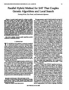
Fig. 1. (a) Schematic of the two-synapse network device. (b) Schematic of the biological two-synapse structure in a simple three-neuron network. (c) Optical microscopic photo of the fabricated two-synapse device.
the postsynaptic neurons, which provides the synapses with computational functions. The solid-state electrolyte gated field effect transistor (EGFET) is a candidate for an artificial synapse cell because the migration of ions in the electrolyte is similar to ion flux between neurons [9] and the three-terminal structure is more common in brains. Furthermore, EGFET can work at very low operation voltage, which is extremely energy efficient [10]–[12]. Some logical calculations have been demonstrated in EGFETs, such as AND, OR [13], and NOT [14]. However, they are all conventional calculation methods, which are different from biological brains. In this work, we demonstrate a two-synapse network, which consists of two top-gate indium-zinc oxide (IZO) thin film transistors gated by SiO2 electrolyte. The IZO semiconductor film is deposited by sputtering at room temperature, making it easy to be patterned and applicable for large scale integration. Its high initial charge density enables transistors with low-voltage performance. The excitatory post synaptic currents (EPSCs) and high-frequency filtering characteristics were demonstrated and they can be controlled by both of the two presynaptic terminals. Furthermore, we demonstrated the neuromorphic frequency coding ADD operation in the two-synapse network, which is in higher similarity with biological synapses and could be the fundamental synaptic computation method for future brain-like computation systems. II. E XPERIMENTAL D ETAILS The schematic of the two-synapse network is shown in Fig. 1(a). The indium tin oxide (ITO) electrodes, SiO2 electrolyte film, and indium zinc oxide (IZO) semiconductor
0741-3106 © 2017 IEEE. Personal use is permitted, but republication/redistribution requires IEEE permission. See http://www.ieee.org/publications_standards/publications/rights/index.html for more information.
WANG et al.: SYNAPTIC COMPUTATION DEMONSTRATED IN A TWO-SYNAPSE NETWORK
1497
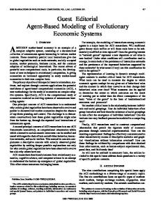
Fig. 2. (a) Protons distribute far from the SiO2 /IZO interface in the SiO2 electrolyte film without gate voltage (VGS = 0V). (b) When positive gate voltage is applied to the gate, protons move to the SiO2 /IZO interface and increase the density of electrons, forming an electric double layer (EDL).
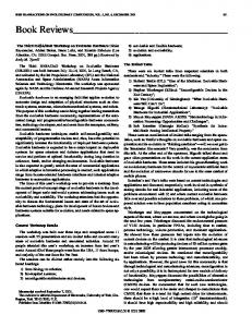
Fig. 3. (a) Equivalent circuit schematic of the two-synapse network. (b) Transfer curves of a single synaptic transistor, in logarithmic Y-axis (blue) and linear Y-axis (red). (c) Transfer curves, by sweeping Gate #1 while biasing Gate #2 from 0V to 1V, with VDS = 50mV. (d) Transfer curves, by sweeping Gate #2 while biasing Gate #1 from 0V to 1V, with VDS = 50mV.
channel can be regarded as presynaptic membrane, synaptic cleft, and postsynaptic membrane, respectively. This structure is highly similar to biological neural networks, as shown in Fig. 1(b). The thicknesses of gate, SiO2 electrolyte, channel, and source/drain are 200nm, 300nm, 20nm, and 100nm, respectively. The ITO and IZO film were deposited by magnetron sputtering and were patterned by the standard lift-off process. The SiO2 electrolyte film was deposited by the plasma enhanced chemical deposition (PECVD) method, at room temperature (25°C) in the ORION III PECVD system, using SiH4 , Ar, and O2 as the reactive gases, with flow rates of 60sccm, 10sccm, and 10sccm, respectively. The RF power and chamber pressure were 100W and 250mTorr, respectively. The protons in the SiO2 electrolyte are hydrogen ions that associated with the bridging oxygen atom, which forms three-coordinate oxygen center (Si-OH+ -Si) structures during the PECVD process [15], [16]. The optical photo of the real two-synapse network device is shown in Fig. 1 (c). The length and width of one synaptic transistor are 16µm and 100µm, respectively. The electrical characteristics of the device and brain-like synaptic computation were demonstrated in a Keithley 4200 semiconductor parameter analyzer system. III. R ESULTS AND D ISCUSSION The equivalent circuit of the two-synapse network is shown in Fig. 3 (a), which consists of two SiO2 electrolyte gated transistors. Firstly, we measured the transfer curve of a single transistor by sweeping the gate voltage from −1V to 1V forward and backward, with VDS = 50mV, as shown in Fig. 3 (b). The insert schematic in Fig. 3 (b) illustrates how the signal was applied. The work
Fig. 4. (a) EPSCs triggered by grouped presynaptic spikes (0.3V, 10ms) with different frequencies, while the other gate was being biased from 0V to 0.3V. Five groups were demonstrated, and each group consisted of 10 spikes. (b) The last peak of the EPSC in each spike group, with frequency as the x-axis.
mechanism of the transistor is shown in Fig. 2. When positive voltage is applied to the gate, the protons in the electrolyte move toward the IZO/SiO2 interface. The electrical fields generated by the protons increase the electron density in the IZO film and form an electric double layer (EDL) at the IZO/SiO2 interface. A counter-clockwise hysteresis window was observed in the transfer curve because the protons at the IZO/SiO2 interface cannot immediately move away when the gate voltage decreased. As a consequence, the short-term synaptic plasticity can be mimicked in the synaptic transistor. This is different from the electron trapping device where a long-term clockwise hysteresis window was observed in the transfer curves [17]. Then, the transfer characteristics of the two-synapse network were tested by biasing one gate and sweeping the other one. The bias voltage increased from 0V to 1V with a step of 0.2V. As shown in Fig. 3(c) and Fig. 3(d), the drain currents increased with the increase of bias voltage because the channel conductance of the biasing transistor was increased. The bias voltage of either gate could control the drain currents when the other gate was being swept. On a short-term time scale, biological synapses can act as filters that respond to stimuli as a function of frequency, dealing with computational tasks within the neural network [18]. The high-frequency filtering characteristics were measured in the two-synapse network, as shown in Fig. 4(a). Five groups of spike stimuli, with same number (10) but different frequency of spikes, were applied to one presynaptic terminal (Gate #1), while the other presynaptic terminal (Gate #2) was biased from 0V to 0.3V. All spikes were in the same amplitude (0.3V) and width (10ms). The time between each group was long enough for relaxation. The drain currents generated by the spikes could be regarded as excitatory post synaptic currents (EPSC).
1498
IEEE ELECTRON DEVICE LETTERS, VOL. 38, NO. 10, OCTOBER 2017
Fig. 5. (a) Two presynaptic spikes (0.3V, 10ms) with interval time (Δt) of 30ms were applied, and two EPSC peaks were measured. There was a current gain (A1/A0) caused by the short-term plasticity. (b) The current gain results of two presynaptic spikes with different interval time (Δt) are plotted.
The peaks of the EPSCs increased with the increase of the stimulus frequency. At the same time, the higher the bias presynaptic voltage was, the higher the EPSC peak would be. It is noteworthy that the EPSC almost did not change with frequency if the other synapse was biased at 0V. To investigate the retention time of the short-term synaptic plasticity, two spikes with different interval times were applied to the presynaptic terminal of a single synaptic transistor, as shown in Fig. 5. In Fig. 5(a), two presynaptic spikes with an interval time of 30ms were applied to the gate electrode of a single synaptic transistor, and the current gain (A1/A0) of EPSCs was 130%. The current gain results of the presynaptic spikes with various interval times were plotted in Fig. 5(b). The longer the interval time was, the lesser the current gain would be. If the interval time increased to 500ms, the current gain was 100%, which reveals that the first spike did not affect the following spike. Furthermore, if frequency coding spikes, instead of steady voltage bias, are input into both presynaptic terminals, the two-synapse network is able to achieve neuromorphic synaptic computation, as demonstrated in Fig. 6. The signals input into the presynaptic terminals were spike sequences coded by frequency. Each operation data was a period (800ms) of spikes in a certain frequency (5Hz, 10Hz, 20Hz, or 40Hz). The spikes were in same amplitude and width (0.3V, 10ms). An example of the ADD computation operation is demonstrated in Fig. 6(b). The spike sequences in 5Hz and 10Hz were applied to the first presynaptic terminal. At the same time, sequences in 20Hz and 40Hz were applied to the second presynaptic terminal. This computation deals with “5Hz ADD 20Hz” and “10Hz ADD 40Hz”. The test was repeated with a reversed frequency order to prove that no effects are left over from the previous pulses. As a result, the EPSC of “10Hz ADD 40Hz” was higher than that of “5Hz ADD 20Hz” and the result can
Fig. 6. (a) Schematics of how the synaptic computation was demonstrated in the two-synapse network. (b) An example of ADD operation, which calculated “5Hz ADD 20HZ” and “10Hz ADD 40Hz”. (c) The ADD results of different combinations of operation data (red point). The color surface is the fitting results of experimental data.
be repeated. The ratio between the last and first EPSC peaks were defined as currents gain (A1/A0), as shown in Fig. 6(b). Different combinations of operation data for stimulus #1 and stimulus #2 were tested. The results are plotted as red points in Fig. 6(c), where the color surface is the fitting results of experimental data. In Fig. 6(c), the higher the frequencies of the two stimuli were, the higher the currents gain would be, which reveal that the two-synapse structure can be used for neuromorphic ADD computations. IV. C ONCLUSION A two-synapse network based on solid-state SiO2 electrolyte gated synaptic transistors was fabricated, and neuromorphic computation was demonstrated in the network. Both of the two synaptic transistors were able to control the EPSCs in the postsynaptic dendrite. The short-term synaptic high-frequency filtering characteristics under the control of the other synapse were tested. A method to achieve synaptic ADD computation based on SiO2 electrolyte gated synaptic transistors in the synaptic network was demonstrated, which could be used in large scale brain-like computation systems.
WANG et al.: SYNAPTIC COMPUTATION DEMONSTRATED IN A TWO-SYNAPSE NETWORK
R EFERENCES [1] D. A. Drachman, “Do we have brain to spare?” Neurology, vol. 64, no. 12, pp. 2004–2005, Jun. 2005, doi: 10.1212/01.WNL.0000166914. 38327.BB. [2] D. Kuzum, S. Yu, and H.-S. P. Wong, “Synaptic electronics: Materials, devices and applications,” Nanotechnology, vol. 24, no. 38, p. 382001, 2013, doi: 10.1088/0957-4484/24/38/382001. [3] L. F. Abbott and W. G. Regehr, “Synaptic computation,” Nature, vol. 431, pp. 796–803, Oct. 2004, doi: 10.1038/nature03010. [4] M. A. Lynch, “Long-term potentiation and memory,” Physiol. Rev., vol. 84, no. 1, pp. 87–136, Jan. 2004, doi: 10.1152/physrev.00014. 2003. [5] D. Kuzum, R. G. D. Jeyasingh, B. Lee, and H.-S. P. Wong, “Nanoelectronic programmable synapses based on phase change materials for brain-inspired computing,” Nano Lett., vol. 12, no. 5, pp. 2179–2186, Jun. 2011, doi: 10.1021/nl201040y. [6] S. Yu, B. Gao, Z. Fang, H. Yu, J. Kang, and H.-S. P. Wong, “A neuromorphic visual system using RRAM synaptic devices with sub-pJ energy and tolerance to variability: Experimental characterization and largescale modeling,” in IEDM Tech. Dig., Dec. 2012, pp. 10.4.1–10.4.4, doi: 10.1109/IEDM.2012.6479018. [7] Y. van de Burgt, E. Lubberman, E. J. Fuller, S. T. Keene, G. C. Faria, S. Agarwal, M. J. Marinella, A. A. Talin, and A. Salleo, “A non-volatile organic electrochemical device as a low-voltage artificial synapse for neuromorphic computing,” Nature Mater., vol. 16, no. 4, pp. 414–418, Feb. 2017, doi: 10.1038/nmat4856. [8] R. S. Zucker and W. G. Regehr, “Short-term synaptic plasticity,” Annu. Rev. Physiol., vol. 64, pp. 355–405, Mar. 2002, doi: 10.1146/annurev. physiol.64.092501.114547. [9] P. A. Schwartzkroin, S. C. Baraban, and D. W. Hochman, “Osmolarity, ionic flux, and changes in brain excitability,” Epilepsy Res., vol. 32, no. 1, pp. 275–285, Sep. 1998, doi: 10.1016/S09201211(98)00058-8.
1499
[10] C. J. Wan, Y. H. Liu, L. Q. Zhun, P. Feng, Y. Shi, and Q. Wan, “Short-term synaptic plasticity regulation in solution-gated indium– gallium–zinc-oxide electric-double-layer transistors,” ACS Appl. Mater. Interfaces, vol. 8, no. 15, pp. 9762–9768, Mar. 2016, doi: 10.1021/ acsami.5b12726. [11] X. Wan, Y. Yang, P. Feng, Y. Shi, and Q. Wan, “Short-term plasticity and synaptic filtering emulated in electrolyte-gated IGZO transistors,” IEEE Electron Device Lett., vol. 37, no. 3, pp. 299–302, Mar. 2016, doi: 10.1109/LED.2016.2517080. [12] J. Wang, Y. Li, Y. Yang, and T.-L. Ren, “Top-gate electric-double-layer IZO-based synaptic transistors for neuron networks,” IEEE Electron Device Lett., vol. 38, no. 5, pp. 588–591, May 2017, doi: 10.1109/ LED.2017.2690278. [13] X. Wan, Y. Yang, Y. He, P. Feng, W. Li, and Q. Wan, “Neuromorphic simulation of proton conductors laterally coupled oxide-based transistors with multiple in-plane gates,” IEEE Electron Device Lett., vol. 38, no. 4, pp. 525–528, Apr. 2017, doi: 10.1109/LED.2017.2665578. [14] J. Wang, Y. Li, Y. Yang, and T. L. Ren, “Low-voltage unipolar inverter based on top-gate electric-double-layer thin film transistors gated by silica proton conductor,” IEEE Electron Device Lett., vol. 38, no. 7, pp. 875–878, Jul. 2017, doi: 10.1109/LED.2017.2700293. [15] A. Lu, J. Sun, J. Jiang, and Q. Wan, “Microporous SiO2 with huge electric-double-layer capacitance for low-voltage indium tin oxide thinfilm transistors,” Appl. Phys. Lett., vol. 95, no. 22, p. 2457, Dec. 2009, doi: 10.1063/1.3271029. [16] A. Lu, J. Sun, J. Jiang, and Q. Wan, “One-shadow-mask self-assembled ultralow-voltage coplanar homojunction thin-film transistors,” IEEE Electron Device Lett., vol. 31, no. 10, pp. 1137–1139, Oct. 2010, doi: 10.1109/LED.2010.2061834. [17] J. Wang, Y. Li, C. Yin, Y. Yang, and T.-L. Ren, “Long-term depression mimicked in an IGZO-based synaptic transistor,” IEEE Electron Device Lett., vol. 38, no. 2, pp. 191–194, Feb. 2017, doi: 10.1109/ LED.2016.2639539. [18] A. M. Thomson, “Presynaptic frequency- and pattern-dependent filtering,” J. Comput. Neurosci., vol. 15, no. 2, pp. 159–202, Sep. 2003, doi: 10.1023/A:1025812808362.