circuit currents of the high voltage systems have been matched by an overspreading network of earth return circuits (pipelines, cables, etc.) close to high-.
IEEE Transactions on Power Delivery, Vol. 9, No. 3, July 1994
1593
A UNIVERSAL MODEL FOR THE COMPUTATION OF THE ELECTROMAGNETIC INTERFERENCE ON EARTH RETURN CIRCUITS H.-J. Haubrich
B. A. Flechner
Institute of Power Systems and Power Economics, University of Technology, Aachen, Germany
ABSTRACT The increasing size of modern electricity supply systems, as well as the higher operating and shortcircuit currents of the high voltage systems have been matched by an overspreading network of earth return circuits (pipelines, cables, etc.) close to highvoltage installations, resulting in a closer inductive and, in the vicinity of earth electrodes, conductive coupling of both system types. The view of the acceptance or inadmissibility of these interferences resulting from the couplings requires the quantification of the physical effects. A computer-simulation leads to reliable forecasts with respect to system stresses and suitable countermeasures. A universally valid algorithm for the calculation of interference voltages and currents in networks of optional topology or with several exposures to power lines is presented and applied to practical problem cases. The algorithm developed is superior to existing models as it simulates uniformly both the inductive and the conductive effects on earth return circuits.
W. Machczyiiski Technical University of PoznaA, 60-965, Poznah, Poland .
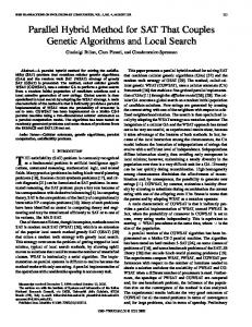
investigation of the interference have been developed [l-61. Such investigations essentially depend on the availability of physical mathematical models for the simulation of the interference. The objective of this paper is to present a universally valid model for the calculation of interference voltages and currents in networks of earth return circuits with several exposures to the fields of electrical supply facilities. Basically, the effects caused by the proximity of the interfering system P (Producer) and the nearby earth return circuit V (Victim) are inductively coupled potentials due to currents in the overhead power line under normal and fault conditions and conductively coupled potentials due to AC and DC electric flow fields of currents flowing into the earth through grounding facilities of electrical installations. These interferences can be calculated with the uniform algorithm shown in Fig. 1.
l " The large-scale expansion of power systems and pipeline systems, combined with the planning concept of concentrating the routes of various supply systems (electricity, gas, oil, telecommunication, etc.) has consequently led to a rise in interference problems. For this reason, a number of projects to study possible effects from exposure to electromagnetic fields caused by electricity supply systems have been launched and some computer-based tools for the
Coupling Matrix V-C
Fig. 1. Computing scheme with injected currents 94 WM 079-4 PWRD A paper recommended and approved by the IEEE Transmission and Distribution Committee of the IEEE Power Engineering Society for presentation at the IEEE/PES 1994 Winter Meeting, New York, New York, January 30 February 3, 1994. Manuscript submitted June 29, 1993; made available for printing December 6, 1993.
-
The basic idea of the algorithm is to transform the electromagnetic field produced by P (e.g. the high voltage transmission line) into a current source IQPV, which drives an element of the system V. This can be an extensive meshed network consisting of pipelines, telecommunication lines or high voltage lines. This network is modelled by its admittance matrix [Yv], thus enabling an easy representation of any optional topology-
0885-8977/94/$04.00 0 1994 IEEE
1594
The calculation scheme is independent of the feeding conditions and of the number of exposures to the interfering system P: the resulting source current is obtained by geometric addition of the single components. When several lines of the network V are simultaneously involved in an exposure, current sources have to be added at the boundary nodes of all interference sections. A necessary presupposition however is the existence of homogenous line sections with uniform exposure to the interfering power lines which have to be approximated by subdivision where needed. Additional extraneous earth return circuits C, e.g. earth wires, metal cable sheaths, special compensation conductors or other underground metal installations, are often involved. Their induced currents IC , determined in the same way as Iv, additionally act upon V by the coupling between C-V, diminishing the interference in case of zero-sequence components of Ip, but also partially increasing it in case of symmetrical operation of the interfering three phase system P. The reaction from V to C cannot be generally neglected; in case of a close proximity V-C, the dashed feedback in Fig. 1 has to be considered. It is assumed in the paper that the reaction of currents in the subjected earth return circuits on the primary electromagnetic field of the electric facilities can be disregarded. Lineariiy of the systems and quasi-stationary behaviour are assumed implicitly.
The starting point for the modelling of insulated, metallic lines with earth return, subjected to the external (primary) electric or magnetic field, is the element of the line of differential length dx, that contains a series impedance 2 = 7 2 , and a shunt where y is the propagation admittance Y' = y/+, coefficient and ZW is the characteristic impedance. Assuming a segment of length I of the line to be homogeneous (e.g. 2 ,Y' = constant), it is possible to model the line by a x-two port with the series impedance
2 =Zwsinh(yl), and the shunt admittance tanh( y Y=
(1a)
@
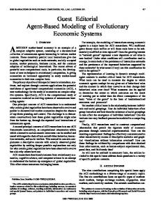
zw ' which is described by a system of transmission equations. If the line is subjected to the effects of an external electric or magnetic field with the intensity E = const., the passive model has to be completed by the current source IQ.This leads to a circuit representation for
the inductive and the conductive interference, respectively [9], shown in Fig. 2. Conductive Interference Homogenous Interference: Homogenous Interference: dUE/dX = E = constant E = constant E voltage gradient of f induced electric field flow field along the line
l
remote earth
remoteearth
dU / dx = -$ZwI - E dI / dx = (-7 /Z;)U
i = I + E / (@), d2U/ dx2 = y2U d2i / d x 2 = r2i
m T remote earth
*
(I2
Fig. 2. Derivation of a uniform source current model for lines subjected to inductive and conductive interference
After being divided into line sections of quasiuniform exposure any network can be composed of such basic two-ports which define the nodes and branches of the passive network model [VI. The resulting network equation [IQ]
(2)
is well suited for computer calculation of the required nodal potentials U and 0, with the source currents IQ, determined by e c
In the case of the inductive interference E = b Gv,c
(3)
(4)
1595
where Z b v , ~is the mutual impedance between the influencing line P and the subjected earth retum circuit and in the case of the conductive interference
For the model from Fig. 3b
Thus Here the scalar potential of the electric flow field along the circuit may be obtained according to [9,10].
[i]+[ iQ] = [Y][Au]
.
(9)
It follows from the equivalence of both systems that [Y] = [Z]--',
In the case of a close proximity between earth return circuits V and C, the mutual interaction has to be considered, according to Fig. 1. For a case of earth return circuits having an insulation of good quality, only the inductive coupling between both conductors appears. The circuit of two inductively coupled lines and its equivalent model are shown in Fig. 3.
[b]=[z3-'[elv where
The electric scheme which realizes the functions of the system 3b, may then be modelled as shown in Fig. 4 (the leakage to ground admittances are not shown in the diagram).
EcYcc+Evyvc Fig. 3. Inductivelycoupled earth return circuits a) basic circuit, b) equivalent model
Fig.4. Electric scheme of the equivalent model of inductively coupled lines
In the basic circuit, subjected to the external inductive effects (EMF E", Ec), Fig. 3a, the inductive coupling between both earth return circuits is represented by voltage sources in the series branches of the equivalent model, where Zv, .is the mutual impedance. The system shown in Fig. 3a may be modelled by an equivalent passive system [Y] (consisting of the self and mutual admittances) with current sources simulating the external excitation modified by coupling conditions (Fig. 3b). The system from Fig. 3a is described by the equations
which may be rewritten in the form
[i]+[ Z]-'[ e] = [Z]-'[ Au] .
(7)
Based on the algorithm described, a user-friendly, PC based computer program has been developed to calculate the potentials coupled into earth retum circuits [8-131.
. .
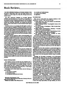
ive effects of a Dower line on DIQG~ES The efficiency of the described algorithm shall be demonstrated by the example of an underground pipeline network whose three branches are exposed to the magnetic induction of a 400-kV-double circuit line (Fig. 5) [8].
1596
E
E
E
E
F“
I) = :1 =1.2 kA
\
E
:=I; -1.2M
-
rv = @.022+J0.017) I h
GV (13.0
+j2 4 ) n
@:nodenunbsr
*&-
a:dbtsncl,inmebf
Fig. 5. Real example of a buried pipeline exposed to the steady state magnetic field of a 400kV overhead line. Construction of the sections with quasi-uniforminduction. pipeline to earth voltages to exceed by far the permitted value of 65V (German Standard), depicted in Fig. 6, curve a. Without suitable protection devices maintenance staff working on the pipeline would be exposed to danger.
constraint U c 65 V
ion of the Drotectiondevtca
0 1 2 3 4 5 6 7 8 9 1 0 length of exposure
km
+
Protective earthing is commonly used and well suited to damp the dangerous potential rise induced by the steady state magnetic field. The search for the most effective earthing points and earthing resistances may be very complicated since the lowresistance earthing of the normally well isolated pipes jeopardizes the efficacy of the cathodic protection. Nowadays computer-aided methods allow an automatic optimization of the protective earthing by lumped resistors. For the case in question, the method of statistical trials has proved to be useful.
Fig. 6. Calculated line to earth induction voltages of the pipeline, according to Figure 5 a) without countermeasures b) earthing resistor of 35Q at node No.10 The length of exposure reaches more than 10 km. Following the discontinuous line configuration and coupling impedances along this length, the pipeline has to be divided into numerous uniform sections corresponding to the vertical propagation of the power frequency magnetic field. The thin reference axes show how to determine the nodes of the pipeline model. The induction caused by a single-phase-to-earth fault was proved to be less critical than by the balanced loading of the 400kV-circuits. This induces
Fig. 7. Examples of the cost function CF and the penalty function PF for the Monte-Carlo optimization The objective function OF=CCb+CPFk
iEm;kE nv
(13)
1597
of this so called Monte-Carlo method includes the costs CF for the protective earthing at m feasible ground connection points (Fig. 7a) and the constraints U