functions (CCF) have been identified by A. Mody [5] as important sequence characteristics in MIMO synchronization. But the original paper did not analyze the ...
Synchronization in OFDM-based WLAN with Transmit and Receive Diversities Ting-Jung Liang, Xin Li, Ralf Irmer and Gerhard Fettweis Vodafone Chair Mobile Communications Systems, Dresden University of Technology, D-01062 Dresden, Germany {liang,xinli,irmer,fettweis}@ifn.et.tu-dresden.de, http://www.ifn.et.tu-dresden.de/MNS Abstract— This paper1 deals with the feasibility of improving synchronization (packet detection and frequency synchronization) of OFDM systems by exploiting transmit and receive diversities. Starting from a performance analysis of SISO synchronization, SIMO, MISO and MIMO synchronization algorithms are proposed and analyzed step by step. Simulations for IEEE 802.11a/g/n-like systems in frequency-selective channels show that the performance of packet detection can be improved by 6.5 dB and the residual frequency synchronization error can be reduced by 68.7%, if 4 transmit antennas and 4 receive antennas are used. For that, carefully designed training sequences and respective transmitter and receiver algorithms are necessary.
I. I NTRODUCTION In present packet-based wireless SISO-OFDM systems, such as IEEE802.11a/g, the synchronization and channel estimation functions are accomplished by a preamble, which is composed of two parts: short training symbols (responsible for synchronization) followed by long training symbols (mainly designed for channel estimation). For MIMO channel estimation [1], the long training symbols must be modified to support different MIMO algorithms, such as V-BLAST and space-time codes. Synchronization in a MIMO system can still be accomplished by selecting a SISO antenna pair and using conventional synchronization methods, like the short preamble in IEEE 802.11a/g. However, if multiple antennas are available at the transmitter and receiver, they should be also used to improve the synchronization performance. The diversity gain used for MIMO data transmission can also be exploited for synchronization, if the short preambles are carefully designed and appropriate algorithms are used. In this paper, we discuss the feasibility of improving packet detection and frequency synchronization. The discussion on synchronization begins with a review of SISO synchronization and the evaluation of its performance. Further, these approaches are extended to SIMO and MISO. From that, MIMO synchronization can be composed. The bases are the relatively simple but widely applied packet detection and frequency synchronization algorithms proposed by T. Schmidl [2]. We do not want to lengthen the preamble and introduce a further transmission delay. Therefore, the length of the IEEE802.11a preamble is also used for the MIMO-OFDM. In this paper, it is assumed that the same oscillator is used for all antennas in each 1 This work was partly supported by the German ministry of research and education within the project Wireless Gigabit with Advanced Multimedia Support (WIGWAM) under grant 01 BU 370
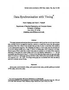
device. The analysis shows that different techniques and design principles are required to exploit the transmit and receive diversities. The simulation results show that the performances of both packet detection and frequency synchronization are improved substantially in a MIMO configuration. II. SISO- AND MIMO-OFDM S IGNAL M ODEL Our packet detection as well as frequency synchronization algorithms are executed in time domain and characterized by the missed detection ratio (1 − PD ) as well as standard deviation σf of estimation error of frequency mismatch (fˆe − fe ). The packet detection is discussed under the assumption of no frequency mismatch fe and the frequency synchronization under assumption of perfect packet detection. In our discussion, an IEEE802.11a-like OFDM-based WLAN system with 64 subcarriers is assumed. The reference model of MIMO systems is shown in Fig. 1. Nt Tx antennas v1[k ]
s1[k]
1Nr [k ]
+
h
r1[k]
v Nr [k ]
Nt
s [k]
h
Nt Nr
[k ]
+
rNr [k]
Fig. 1. Reference model of MIMO system with Nt Tx antenna and Nr Rx antenna (time index k)
are used and Nr Rx antennas, with the respective indices nt and nr . The transmitted short training symbols of transmit antenna nt , channel impulse response (CIR) of antenna pair (nt , nr ), noise and received short training symbols at receive antenna nr are snt [k], hnt nr [k], v nr [k] and rnr [k], respectively. The sample index is k. Regardless of the numbers of transmit antennas, the total Tx power is limited to Pt . The SNR= Pt /σv2 is defined as the total transmitted power divided by the noise power at one receive antenna. The power of the additive white Gaussian noise v nr [k] is σv2 . The structure of the IEEE802.11a short training symbols can be found in [3]. It is composed of 10 repeated sequences. Each sequence has length P = 16 samples, hence the short preamble consists of 160 samples, with sampling time Ts = 50 ns. The design of training sequences with transmit diversity may change the period of the repeated part, but the total
length is always assumed to be 160 samples. The system under discussion has maximally four transmit and four receive antennas, which are assumed to be uncorrelated.
B. Frequency Synchronization in SISO-OFDM The metric of frequency synchronization in [2] ignoring noise is: ϕ[k] =
III. S YNCHRONIZATION IN SISO- AND SIMO-OFDM
L−1 X
r[k + i]r∗ [k + i + P ]
i=0
The packet detection and frequency synchronization algorithms proposed by T. Schmidl [2] are widely used in SISOOFDM. The received short training symbols with frequency mismatch fe can be written as r[k] = s[k]ej2πkfe Ts + v[k] under the AWGN assumption as in the original paper. A. Packet Detection in SISO-OFDM The metric of packet detection in [2] is: 2
M [k] =
|c[k]| p[k]2
(1)
The correlation and power: c[k] and p[k] are defined as: c[k] = p[k] =
L−1 X i=0 L−1 X
r[k + i]r∗ [k + i + P ]
(2)
r[k + i + P ]r∗ [k + i + P ]
(3)
=
"L−1 X
# |s[i]|
2
e−j2πP fe Ts
(4)
i=0
The estimated frequency mismatch is: fˆe =
−1 ∠ϕ[k] 2πP Ts
(5)
The period P of repeated short ¯preamble limits the maximal ¯ ¯ ¯ assessable frequency mismatch ¯fˆe ¯ 5 2P1Ts which is caused by oscillator mismatch (e.g. 212 ¯KHz ¯ in IEEE802.11a [4]) ¯ ¯ and Doppler effect. The maximal ¯fˆe ¯ of the frequency offset estimator is 625 kHz with P = 16 and Ts = 50 ns. The worstcase tolerable Doppler shift is 625-212=413 kHz. However, only 1 kHz Doppler frequency is introduced at around 200 km/h and carrier frequency 5.2 GHz. The normalized frequency mismatch is defined as ”frequency mismatch” divided by ”subcarrier spacing” (fe /fsub ). Fig. 3 shows that the normalized residue frequency mismatch should be smaller than 1% to ensure BER better than 10−3 in the frequency-selective fading channel model Hiperlan/2 A (H2A).
i=0 0
10
-2
10
AWGN H2A
-4
10
BER
with L = 160 − P in numerical examples. The purpose of the operation in the L = 2P range is to average random noise. One packet is claimed as detected, if the metric at the receiver is larger than a pre-defined threshold η. It has impact on the probability of false alarm PF A and missed detection probability (1 − PD ). A packet is regarded as detected if the detection offset is in the range of the long guard interval, e.g. ±32 samples [4]. One example of the impact of η is shown in Fig. 2. If a system is designed with PF A < 10−10 ,
-6
10
-8
10
-10
10 0
10 0
10
SNR=5dB
PFA
1-PD
-5
0.02
0.04
0.06
fe / fsub
0.08
0.1
Fig. 3. The impact of normalized residue frequency mismatch on BER in IEEE802.11a (SNR=10dB)
10-5
SNR=10dB
10
0
C. SIMO-OFDM - Receive Diversity and Numerical Examples SNR=5dB -10
10-10
10
SNR=10dB -15
10
0
0.2
0.4
0.6
Threshold η
0.8
10-15
1
Fig. 2. Left curve: the impact of threshold η on the probability of false alarm (PF A ) in AWGN and Right curve: the impact of threshold η on the missed detection ratio (1 − PD ) in AWGN
1 − PD < 10−3 , and SNR=10dB, the threshold value η = 0.7 is appropriate.
Equal Gain Combining (EGC), Maximal Ratio Combining (MRC) and Selective Combining (SC) can all exploit the receive diversity. The EGC algorithm averages the metrics M [k] and fˆe of the individual receive antennas. In MRC weights additionally the individual metrics by the received power. The SC selects the antenna with the highest receive power. For simplicity, we consider following only EGC. The comparisons of synchronization between SISO and SIMO are shown in Fig. 4 and Fig. 5. The same missed detection rate target 1 − PD = 10−3 can be reached with 2.1 dB or 2.9 dB transmit power saving, if two or four receive antennas are used for packet detection. The standard deviation σf of the
0
Then the cyclic shift in time domain is introduced as a useful design trick, followed by its applications to practical training sequences.
10
1Tx 1Rx (16) 1Tx 2Rx (16) EGC 1Tx 4Rx (16) EGC
-1
10 1-PD
B. Analysis of Metrics -2
10
1) Packet Detection: A block flat fading channel (hnt nr [k] = hnt nr , ∀ k) is assumed. In (2) we substitute the received signals ignoring frequency mismatch (fe = 0) into the metric. Using the fact of sequence repetition, the correlation term cnr [k] at receive antenna nr can be expanded as:
-3
10
-4
10
0
5
10
SNR
15
20
25
nr
Fig. 4.
The performance of packet detection with receive diversity in H2A 5
c [k] = L−1 Xh
(s1nr [k + i])∗ s2nr [k + i](h1nr )∗ h2nr
i=0
1Tx 1Rx (16) 1Tx 2Rx (16) EGC 1Tx 4Rx (16) EGC σ f [Hz]
¯ ¯ ¯ ¯ ¯ ¯ 1n ¯ ¯ i ¯s r [k + i]¯2 ¯h1nr ¯2 + ¯s2nr [k + i]¯2 ¯h2nr ¯2
i=0
+
10
L−1 Xh
+ s1nr [k + i](s2nr [k + i])∗ h1nr (h2nr )∗
4
+
10
L−1 Xh
i
∗
∗
v nr [k + i] (αnr [k + i]) + αnr [k + i] (v nr [k + i + P ])
i
i=0
(6) 3
10
0
2
4
fe [Hz]
6
8 5
x 10
Fig. 5. The performance of frequency synchronization with receive diversity in frequency-selective fading channel Hiperlan/2 A (H2A), SNR=10dB
with αnr [k] = s1nr [k]h1nr + s2nr [k]h2nr . The new power term pnr [k] (3) is the same as the correlation term cnr [k] (6) except that the third noise term in (6) is replaced by: L−1 Xh
i ∗ ∗ v nr [k + i] (αnr [k + i]) + αnr [k + i] (v nr [k + i]) . (7)
i=0
frequency offset estimation error fˆe − fe can be improved by 25.9% and 47.2% with 2 or 4 Rx antennas. The transmitted IEEE802.11a short training symbols the period P = 16 ¯ have ¯ ¯ ¯ and the corresponding maximal ¯fˆe ¯ (625 kHz) does not depend on the number of receive antennas. IV. S YNCHRONIZATION IN MISO-OFDM A. State of Art - Short Training Symbol Design exploiting Transmit Diversity Good autocorrelation functions (ACF) and crosscorrelation functions (CCF) have been identified by A. Mody [5] as important sequence characteristics in MIMO synchronization. But the original paper did not analyze the metrics formed by IEEE802.11a-like sequences with repetition structure and it did not provide training sequence design regarding channel models and the period of repeated block, too. In addition, both the PAPR and the capability of differentiating SISO and MIMO preambles at the receiver should also be considered in a practical design. In our design, the same metrics (1), (4) as in SISO-OFDM are used. The total length of the preamble is limited to that of SISO-OFDM. The received short training symbols with antennas can¢ be written as: rnr [k] = ¡ 1n two 1ntransmit 2n s r [k]h r [k] + s r [k]h2nr [k] ej2πkfe Ts + v nr [k] under the flat fading channel assumption. The sequence design begins with the analysis of metrics in flat fading channel.
Additionally, the expectation value of the metric M nr [k] is assumed to be 1. 2) Frequency Synchronization: The metric of frequency synchronization with multiple transmit antennas ignoring noise is written as: ½L−1 X h¯ ¯ ¯ ¯ ¯ i ¯ ¯ ¯ nr ¯s1nr [k + i]¯2 ¯h1nr ¯2 + ¯s2nr [k + i]¯2 ¯h2nr ¯2 ϕ [k] = +
i=0 L−1 Xh
(s1nr [k + i])∗ s2nr [k + i](h1nr )∗ h2nr
i=0
+s
1nr
[k + i](s
2nr
∗ 1nr
[k + i]) h
(h
2nr ∗
)
i¾
e−j2πP fe Ts (8)
The estimated frequency mismatch is the same as in (5). The maximal assessable frequency mismatch depends on P and Ts , too. 3) Requirements of Short Training Symbols: Under the assumption of block flat fading channel, we learn that a) Transmit diversity can be well exploited because one transmitted signal in the first term of equation (6) and (8) can support another transmitted signal facing deep fading. b) Good timedomain CCF with zero time shift, which minimize the second term in equation (6) and (8) are crucial for sequence design. Furthermore, the frequency selective channel introduces superimposed terms (multipath) with any time shift smaller than the maximal length of channel impulse response (CIR) in the
metrics. According to equation (6) and (8), the performance in frequency selective fading channel can be optimized by training sequences with good time-domain ACF and CCF within any time shift smaller than the maximal CIR length.
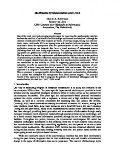
The FZC code with full spectrum in use has perfect PAPR (0 dB) and perfect ACF (F factor is ∞) regardless of P . The ACF and CCF of FZC codes with spectrum mask (52 subcarriers available), and 16 samples cyclic shift (P = 32 and MISO 2x1) is shown in Fig. 7. The F factor for ACF is 0.845 between
C. Cyclic Shift in Time Domain Cyclic shift in time domain [6] is a practical algorithm to generate a group of sequences with good time-domain CCF based on a ’seed’ sequence with good ACF. The unit of cyclic shift in time domain is P/Nt . The period of the repeated block P , the characteristics of ACF, such as the F factor (Normalized energy of central lobe / normalized energy of all non-central lobe), and PAPR do not change after cyclic shift in time domain. The time-domain CCF of group sequences is the same as the original time-domain ACF of the ’seed’ sequence with time shift P/Nt , which must be larger than the CIR length. D. Discussion of Practical Training Sequences Three sequences: IEEE802.11a short training symbols, Frank-Zadoff-Chu (FZC) [7] codes with time-domain cyclic shift and ITRI sequences [8] are discussed respectively. 1) IEEE802.11a Short Training Symbol: The IEEE802.11a short training symbol is composed of 10 repeated sequences, each of which is 16 samples long. The F factor for ACF is 0.749 between [-8:8] considering the maximal CIR length of the H2A channel model. The digital PAPR of IEEE802.11a short training symbols with 8 times oversampling is 4.1dB. The ACF and CCF of IEEE802.11a short training symbols with 8 samples cyclic shift (for MISO 2x1) is shown in Fig. 6. 1
1
0.5
0.5
0
0
-0.5 -30 -20 -17 x 10 2
-10
0
10
20
30
real
-0.5 -30 -20 -17 x 10 2
0
0
-2
-2
-4 -30
-20
-10
0
10
20
30
-4 -30
-20
imag
-10
0
10
20
30
10
20
30
real
-10
0
1
1
0.5
0.5
0
0
-0.5 -60 -40 -14 x 10 1
-20
0 real
20
40
60
-0.5 -60 -40 -14 x 10 1
0
0
-1 -60
-1 -60
-40
-20
0 imag
20
40
60
-40
-20
0
20
40
60
20
40
60
real
-20
0
imag
Fig. 7. The periodic autocorrelation (left) and crosscorrelation (right) functions of Frank-Zadoff-Chu (FZC) codes with spectrum mask and 16 samples cyclic shift
[-8:8] and the PAPR is 4.05 dB. 3) ITRI Sequences: The MISO 4x1 short training symbols proposed by ITRI [8] have perfect CCF, but worse ACF (F factor 0.56 between [-8:8] in average) than FZC codes with spectrum mask. In addition, the PAPRs of ITRI sequences are 5.4, 6.4, 4.5 and 7.0 dB for antena 1, 2, 3, 4, respectively. E. Performance of WLAN with Transmit Diversity The performance of IEEE802.11a-like WLAN systems with different transmit antennas, training sequences and channel models is evaluated by simulation. Using FZC codes (P = 32, H2A) with spectrum mask, systems with two and four transmit antennas have an acquisition improvement of 3.3 dB or 4.5 dB, if 1 − PD = 10−3 as shown in Fig. 8. The frequency synchronization performance σf of (fˆe − fe ) is improved by 35.1% as well a 41.5% compared to SISO-OFDM, as shown in Fig. 9. The FZC codes with full spectrum have perfect ACF and CCF for the H2A channel. Their performance should serve as the lower bound for H2A channel. Fig. 8 and 9 show
imag 0
10
Fig. 6. The periodic autocorrelation functions (left) and crosscorrelation functions (right) of IEEE802.11a short training symbol (P = 16) with 8 samples cyclic shift
-1
10
1-PD
2) Frank-Zadoff-Chu (FZC) Code: The definition of FrankZadoff-Chu (FZC) codes [7] with index 5 and time-domain period P is:
1Tx 1Rx (16) H2A 2Tx 1Rx FZC (16,Spectrum Mask) H2A 2Tx 1Rx FZC (32,Spectrum Mask) H2A 4Tx 1Rx FZC (32,Spectrum Mask) H2A 4Tx 1Rx FZC (32,Spectrum Mask) H2E 4Tx 1Rx ITRI (32) H2A 4Tx 1Rx FZC (32,Full Spectrum) H2A
-2
10
-3
10
5n jπk2 /P
FZC[k] = (−1) e
,
0