To measure synchronization in this condition the setup is straightforward and ... master, best results are obtained when an Android mobile phone is used as ...
Synchronization methods for Bluetooth based WBANs Filippo Casamassima, Elisabetta Farella, Luca Benini Dipartimento dell’Energia Elettrica e dell’Informazione DEI University of Bologna {filippo.casamassima, elisabetta.farella, luca.benini}@unibo.it
Abstract—Wireless Body Area Networks (WBANs) can take advantage of many wireless protocols. Among them, Bluetooth is a good candidate since its widespread adoption guarantees compatibility with a number of devices and significantly reduces development time. In most cases data collected from different sensors on different nodes need to be synchronized. We present a synchronization protocol that makes use of Bluetooth piconet internal clock to achieve near-millisecond accuracy with minimal radio communication overhead. Experimental results show that Bluetooth low power modes does not affect negatively accuracy, but improves it, obtaining less power consumption and higher synchronization accuracy.
I. I NTRODUCTION Wireless Body Area Networks (WBANs) experienced an exponential growth of interest during the last decade. Advances in both industrial and academic research lead to highly integrated MEMS sensors (e.g. from single-axis accelerometers to sophisticated IMUs), powerful and energy efficient microcontrollers (e.g. such as 32-bit AVR UC3 or 32-bit ARM Cortex MCUs), compact and efficient batteries and radio solutions. According to the specific WBAN needs, different radio protocols can be used (e.g. ZigBee, Ant, UWB, Bluetooth, Bluetooth Low Energy) each of them with specific advantages and drawbacks. Among them, Bluetooth guarantees both high data rate (up to 2Mb/s) and inter-operability with a number of devices. However, while early WBAN applications required in many cases just a single node [1], more and more the number of nodes is increasing to monitor diverse physiological parameters (e.g. motion, temperature, pressure, galvanic skin response, etc.) or to track the same parameter but at different body location [2]. In such cases and particularly when sensor fusion algorithms need to be used, a common time reference among all WBAN nodes is necessary. The level of accuracy required for WBAN synchronization depends on the application and on the parameters to be monitored (e.g. for temperature monitoring also 1 sec error might be acceptable, while for ECG or inertial measurements, errors above 1 ms can not be tolerated [3]). Data synchronization might be also performed through wired sensors, but this is an uncomfortable solution. This paper addresses the problem of synchronization in a Bluetooth based WBAN where sensors are placed on human body for gait analysis. Target users are Parkinson’s Disease (PD) patients, for which parameters of interest are gait velocity, cadence, legs rotation while walking,
legs and arms movement symmetry, etc. In this context, it is reasonable to have more than one node to improve accuracy, but not so many to limit usability. The novel method proposed in this paper enables: (i) to achieve 1ms accuracy in a Bluetooth network, (ii) to perform synchronization with no communication overhead and simple modifications to sensor node’s firmware (iii) to achieve higher performance when Bluetooth low power modes are used. The rest of the paper is organized as follows: we survey related works in section II. The paper continues then with section III where we show two synchronization methods for a COTS WBAN setup. Finally in section IV, we present results of measurements in terms of synchronization error, with the conclusions presented in section V. II. R ELATED W ORK The time synchronization problem for wireless networks has been extensively studied in literature over the last two decades and yet there is no specific time synchronization scheme capable to guarantee higher order of accuracy with greater scalability, independently from topology and application [4]. There are four main sources of delays that must be accounted for to have accurate time synchronization: (i) transmission time; (ii) access time; (iii) propagation time and (iv) reception time [5]. Among most common synchronization schemes in Wireless Sensor Networks (WSN) it is possible to find the Reference Broadcast Synchronization (RBS) method. The advantage of this method is the elimination of the uncertainty of the transmission time by removing the sender from the critical path [6]. Timing-sync Protocol for Sensor Networks (TPSN) can reduce send time uncertainty but not remove it, although it is not affected by transmission range like RBS and claims to be twice more accurate [7]. Another time-sync class of protocol is Flooded Time Sync Protocol (FTSP) [8]. This protocol is similar to TPSN, but it improves on the disadvantages to TPSN [9]. A comprehensive review on synchronization for WSN can be found in [10]. Different approaches have been published in the literature that addresses the problem of synchronizing Bluetooth based networks. Some approaches borrow algorithms from WSN and send a common time reference through an explicit message [11]. Protocols based on the exchange of explicit synchronization messages suffer from highly variable messages latencies typical of Bluetooth implementations.
In [12], for example, round trip time in a simple two-nodes network varied between 30 and 230 ms with a 76 ms average. It is also possible to use packet reconstruction mechanisms able to deliver up to 10ms accuracy [13]. Such values are too high to have an acceptable synchronization when inertial or ECG sensors are used. Other works make use of broadcast messages sent to all slave nodes; in this case a statistical analysis of reception instants can further improve precision; in [14] authors were able to achieve precision in the order of ten microseconds using one master node and two slaves. Although not all Bluetooth modules are able to send and receive broadcast messages, the modules on which measures have been performed in [14] gave access to Host Control Interface Layer (HCI). Our implementation does not require HCI access, it is applicable at higher-level (Bluetooth-MCU communication level). If data rate and number of nodes in the network is constant, it is possible to exploit an intrinsic characteristic of Bluetooth stack: the assignment of time slots. In this particular case it is possible to find a perfect match between data rate and assigned time slots. In [15] authors were able to reach microsecond accuracy using information on assigned time slots, although such setup implies that number of nodes and transmission rate is constant. This is not always true in a WBAN. Unlike other approaches, the synchronization method proposed by this paper is built on top of the Bluetooth radio stack; moreover, it is possible to use this method without communication overhead, and with simple modifications to sensor node’s firmware. III. S YNCHRONIZATION ON B LUETOOTH WBAN In the following, we explore two approaches: the first uses the information on the data reception time from the master and the latter is based on the information provided by the Bluetooth Piconet Clock. For each of them we will evaluate possible improvements and application scenarios. A. WBAN synchronization: application requirements In the context of WBAN we are developing a system for gait monitoring and analysis, thus our requirement is to use inertial sensors to identify benefits of a rehabilitation therapy or drug on motor behaviour. Synchronization among nodes is crucial to identify small improvements and specific parameters such as gait symmetry. The requirements of our application, concerning radio protocol can be summarized as follow: - High data rate (a minimum bandwidth of 500kb/s is needed, but 2Mb/s are desirable). - Easy interoperability with other devices such as computers, smart-phones or tablets. - Network size from 3 to 7 nodes plus a master device. - Synchronization error must be lower than 1ms. - Good noise immunity and transmission range compatible with WBAN applications. Sensor nodes should maintain synchronization during data streaming, and during data logging, when few or no data is transmitted through the radio. Those requirements lead to the
Fig. 1.
Picture of a sensor node
choice of Bluetooth technology. Our WBAN is based on identical nodes (shown in Fig. 1) each of them equipped with inertial sensors, a micro-controller, NAND FLASH memory, Bluetooth radio and a battery. Data from sensors are sampled at a frequency that can vary from 50Hz to 400Hz, system can operate with a minimum of 3, up to 7 sensor nodes. Other radio protocols such as ANT or Zigbee do not have sufficient data throughput (16 bit x 9 DOF x 400Hz x 7 sensors). Unfortunately, Bluetooth does not provide a high-level mechanism to synchronize data with accuracy needed for our application. Simple synchronization methods in a Bluetooth network can achieve accuracy in the order of tens of microseconds [12], which is unacceptable for gait monitoring, since some gait parameters like heel strike have a duration of few milliseconds [16] [17]. When it is necessary to combine information of multiple sensors to reconstruct gait parameters, synchronization method should provide time resolution similar or better than the sampling frequency [18]. B. Time Of Arrival Bluetooth channels use a Frequency-Hop/Time-DivisionDuplex (FH/TDD) scheme. Transmission/reception takes place in timeslots that are 625 microseconds in duration. The masterto-slave transmission starts in even numbered slots, while the slave-to-master transmission starts in odd-numbered slots. Masters and slaves are allowed to send 1, 3, or 5 slot packets, which are transmitted in consecutive slots. Information can only be exchanged between a master and a slave. A slave is allowed to start transmission in a given slot, if the master has addressed it in the preceding slot. The master addresses a slave by sending a data packet or, if it has no data to send, a 1-slot POLL packet. The slave must respond by sending a data packet or, if it has nothing to send, a 1-slot NULL packet. In many WBAN applications, when continuous monitoring is needed, data are sent periodically with the same time interval. This is the case we want to analyse to synchronize data on the receiver side. In a Bluetooth network, when sensor nodes periodically send data, if the receiver node (usually also master node) is aware of the transmission rate that each sensor uses to send data, it is theoretically possible to synchronize data coming from different nodes. This can be done thanks to the (FH/TDD) scheme (i.e. transmission occurs only in periodic time slots). Unfortunately, this kind of setup would also allow limited flexibility, since adding or removing a node, or modifying transmission rate will affect time slot assignment. For this
shown in the figure below. The most common interfacing is done through the UART interface by using the ASCII commands that iWRAP firmware supports. With these ASCII commands, the host can access Bluetooth functionality without paying any attention to the complexity, which lies in the Bluetooth protocol stack. GPIO interface can be used for event monitoring and command execution. PCM, SPDIF, I2S or analog interfaces are available for audio. The available interfaces depend on the used hardware.
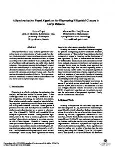
Sigma of delay distribution (ms)
The user can write application code to the host processor to control iWRAP firmware using ASCII commands or GPIO events. In this way, it is easy to develop Bluetooth enabled applications. On WT32 there is an extra DSP processor available for data/audio processing.
100 80 60 40
50Hz 100Hz 200Hz 400Hz
20 0 0
500
1000 1500 Data rate (samples/sec)
2000
iWRAP
2500
Fig. 2. Synchronization measurement results, data rate is dependent from sampling frequency and number of nodes connected UART / USB
reason, almost all Bluetooth devices have a buffer capable to store incoming data from sensors and transmit them when one or more time slots are assigned by the piconet’s Master. To measure synchronization in this condition the setup is straightforward and simple: a single timer runs on the receiver node and when data are received, the sensor’s value is stored together with timer value. This synchronization method is easy to implement and does not add any overhead to data communication, but requires continuous and constant data streaming from sensors. Different setups have been tested: using multiple nodes and using different devices as network master, best results are obtained when an Android mobile phone is used as master. This configuration allows to stream data from 6 sensors sampling at 400Hz. Results of this synchronization method are shown in Fig. 2 and are compatible with a similar approach described in [19]. From the graph, it is possible to notice that synchronization error increases with data rate, but it also depends on the number of nodes connected. Moreover, this approach is strongly dependent on the master, on the implementation of the Bluetooth stack and on the operating system and workload; in fact, tests with a supposedly more powerful computer achieves worse results than a phone. Therefore the approach is not robust and scales poorly. Unfortunately, those results did not meet the requirements of our application; the delay is strongly dependent on the number of connected nodes, on the master device and on data rate. Moreover, in many cases synchronization error is above 10ms, unsuitable to produce an accurate gait analysis. C. Bluetooth piconet clock The Bluetooth clock is a 28-bit counter with 0.3125 ms resolution and a mandatory maximal drift of ±20 ppm. This results in an overrun every 228 × 0.3125 ms ≈1 day. Each Bluetooth device has a unique 6-byte base-band address (BD ADDR) similar to the medium access control address of Ethernet devices. The hopping sequence is a pseudorandom sequence of communication frequencies calculated from the BD ADDR of the piconet master device. Because of the frequency hopping, a special procedure called inquiry is required to discover other devices (i.e. their address and hopping sequence). During an inquiry, a device uses a special inquiry hopping sequence and doubles its hopping rate to rendez-vous with other devices. As a result of an inquiry, the
GPIO / AIO
Hardware PCM / I2S / SPDIF
Analogue
Figure Bluetooth Fig. 3.1: iWRAP Bluetooth stack stack implemented
in WT12 modules
BD ADDR and the difference between the local Bluetooth clock and the clock of the remote devices are acquired. Based on this information, a node can calculate the hopping sequence of discovered nodes and is thus able to connect to these devices. Bluegiga Technologies Oy Page 10 of The clock offset between two connected devices is269 specified as the difference between the clock of the slave node (CLKslave) and the clock of the master node (CLKmaster). Each slave node stores in a local register the offset, this value can be used to reconstruct the CLKmaster, so that all nodes refer to a common clock. It is thus possible to use the reconstructed CLKmaster value to synchronize all nodes. Measuring the offset between the system clock and a Bluetooth clock is non-trivial as reading the Bluetooth clock requires sending a command message to the Bluetooth modem over the serial interface between the main processor and the Bluetooth modem and receiving a reply message (a so-called event) over the serial interface that contains the requested clock value. Reading piconet clock: Our purpose is to use a standard Bluetooth adaptor and measure the value of the common clock present in the piconet. Before explaining our clock reading procedure, we will briefly introduce Bluetooth stack elements since this helps to understand our results, our methodology and the source of error when reading piconet clock. The Bluetooth protocol stack is split in two parts: a ”controller stack” containing the time-critical radio interface, and a ”host stack” dealing with high-level data. Controller stack is composed by: 1) Bluetooth radio: it is the transceiver that transmits and receives modulated electrical signals from peer Bluetooth devices. It is not part of the stack since it is a physical chip but directly communicates with the baseband layer. 2) Baseband: it is the physical layer of the Bluetooth,
D. Piconet clock synchronization method Our synchronization method has been implemented on Bluegiga WT12 Bluetooth module that uses a proprietary Bluetooth stack called iWrap shown in Figure 3. WT12 modules have the flexibility to be controlled using iWrap firmware or alternatively bypass it and use HCI commands. We choose the former alternative since our micro controller host cannot run application firmware and Bluetooth stack. Our configuration had 7 slaves sensor nodes and one master device. The master after issuing and establishing a connection using Serial Port Profile (SPP) to slave nodes, was able to send commands to manage sensor’s operations and eventually to receive data from them. In addition if Bluetooth implements
WT12
BT radio is switched to command mode
1
MCU
which manages physical channels and links apart from other services like error correction, data whitening, hop selection and Bluetooth security. 3) Link Manager: it essentially handles link set-up, security and control. It also manages devices in different modes (Park, Hold, Sniff and active). While the host stack contains: 1) L2CAP: it is the Logical Link Control and Adaptation Layer protocol. L2CAP permits higher-level protocols and applications to transmit and receive L2CAP data packets. 2) RFCOMM: it is the protocol that emulates the serial cable line settings and status of an RS-232 serial port and is used for providing serial data transfer. RFCOMM connects to the lower layers of the Bluetooth protocol stack through the L2CAP layer. Communication between host stack and controller stack is performed through the Host Control Interface, a standardized interface with common commands that allow communication also through different hardware devices [20]. The information that we need (the piconet clock, or shift between Master clock and Slave Clock) is updated in the Baseband layer, which is accessible though HCI. The implementation of the host stack is never trivial; there are essentially three options: one is to buy the license for a proprietary Bluetooth stack; a second one is to develop or port an existing stack to the desired platform; a third one is to use modules that already implement a stack with different profiles. For the latter case, it is not always possible to send direct HCI commands to the host stack, because HCI communication is managed by other software/hardware components that are not accessible. This is a very common situation, to reduce developing time and costs, sometimes a solution that works out of the box is chosen; many vendors implements specific command to read piconet clock. To read piconet clock value it would be desirable to have direct access to baseband layer (Figure 3) in order to obtain minimum communication overhead and delay. As said this is not possible, since lower accessible level is HCI. The complexity of Bluetooth stack (and often the presence of two separate chips) clarifies the reason why in many cases reading piconet clock is inaccurate.
Fig. 4.
Last data from sensor is collected
2
4
3
Switch to command mode
BT Clock is acquired
5
“Read Clock” command
BT radio is switches to data mode
6
7
Switch to data mode
8
MCU timer is resetted and sensor acquisition restarts
Sequence of operation performed during to read piconet clock
MCU to Bluetooth Bluetooth Processing clock value response
Bluetooth to MCU Command packet Bluetooth response
t1 t2≈t3
t1 t2
queue delay
t3
Data traffic
Fig. 5. Description of how the ”read clock” command is processed by a Bluetooth module [22]
a Health Device Profile (HDP), SPP has been chosen since for data streaming the two profiles are comparable in terms of packet loss [21].
E. Bluetooth clock As first approach, we choose to read piconet clock at regular intervals using the iWarp command “CLOCK {link id}” where link id specifies the connection of which clock is read, since Bluetooth module can be part of different Bluetooth networks, thus having different values for piconet clock. In our case all sensor nodes are slaves, thus the command is “CLOCK 0”. Unfortunately, commands cannot be sent to Bluetooth module once the connection has been established: all data sent by the sensor node MCU to the WT12 module are retransmitted to the master node. If the connection drops or is intentionally closed, it is possible to issue commands to WT12. The alternative is to switch the module from ”data mode” (default mode when connection is established) to ”command mode” (default mode when no connection is established); this can be done sending a special character, but the whole operation requires at least 2 seconds or configuring the node to switch mode raising a pin. The operations to be performed to read the Bluetooth clock are shown in Fig. 4. Once the Bluetooth clock is read, the value is stored together with data on the NAND flash memory on the node, or a special packet is sent to the master node. Accuracy of our synchronization method was measured using the following setup: a pin from each of the sensor node MCU was connected to the same cable; firmware on MCU was configured to detect interrupt on that pin with the highest priority and read piconet clock when such interrupt is detected. Piconet clock value is then compared among all nodes. We had unsatisfactory results with the described configuration: synchronization error had a mean value of 15ms and was often above 30ms.
20 Sinch error Average +σ −σ
15 Sinch Error (ms)
Since all Bluetooth nodes in a piconet must be synchronized and the clock offset with respect to the master node is stored in the Baseband layers, we suspected that such delay was due to Bluetooth stack operations performed by the host controller on WT12 modules. We indeed noticed that the response time to the read clock command was not constant. Our hypothesis is that the command is received and processed in a constant time, but the response time can vary according to how busy the host controller is. Figure 5 represents what happens when a command is issued to Bluetooth node. It is possible that when the command is issued (t1 ), the host controller is busy for other operations [22], and the response does not occur soon after processing (t2 ), but instead may be delayed and sent after completing other operations (t3 ). It has to be noted that the Bluetooth module does not transmit any data while in command mode, but it can accept incoming connections and is visible to other devices. Furthermore, incoming data are buffered, thus we can infer the host controller is busy in random times. In this condition, it is possible to remedy and mitigate correcting the received piconet clock. It is indeed possible to start a timer on the sensor node MCU right after the last byte of the command is sent to the WT12 module and stop the timer when the first byte of the response is received. Therefore, all the modules will start the timer with equal delay (sending the command requires the same amount of time on every node). The piconet clock value can be then corrected using the value of the timer. The above approach result in a systematic error, which equals the time between the transmission of the command and the actual readout of the piconet clock. This systematic error can be easily cancelled since we use Bluetooth clock as time reference and the time difference between two measures elides the error.
is large (compared to the Sniff window). If TSnif f is in the region of a second and the duration of Sniff is in the region of several ms, the consumption will be about 1 to 5% of the maximum transmission consumption (average consumption in our module ranges from 3mA to 5mA approximately). In our synchronization method, we hypothesised that piconet clock readings were delayed because the host stack was busy. Using Sniff mode we should increase accuracy; experimental results confirms this hypothesis.
10 5
}σ
0 −5 −10 −15 0
Fig. 6.
50
100
150
200 250 300 Number of samples
350
400
450
500
Synchronization error after correcting the Bluetooth clock value
4 Sinch error Average +σ −σ
3 2 Sinch Error (ms)
F. Bluetooth clock correction
1
}σ
0 −1 −2 −3 −4
50
100
150
200 250 300 Number of samples
350
400
450
Fig. 7. Synchronization error excluding piconet clock values when reading time is above 125ms
G. Improving piconet clock correction Our analysis has been moved to the piconet clock acquisitions with the higher synchronization error, trying to find a feature that may allow to filter them out. Our efforts have been repaid when we noticed that the acquisitions that required more time are also the ones with higher error. A simple threshold filter has then been implemented on the MCU cutting out piconet clock values that requires 5% more than the average reading time. In this case, a new acquisition can be made if the reading time is in the acceptance range. H. Low power performance Since WBAN nodes relies on batteries, power management is crucial to extend sensor node’s operating time. Bluetooth protocol provides some low power mode (Park, Sniff, Hold). Among them Sniff mode is the more appealing since combines module’s responsiveness and low power consumption. A Bluetooth module in the Sniff mode stays synchronised in the piconet. It listens to the piconet at regular intervals (TSnif f ) for a short instant. This enables it to re-synchronise with the piconet and to be able to make use of this Sniff window to send or receive data. The consumption is as low as the TSnif f
IV. S YNCHRONIZATION ACCURACY ASSESSMENT We present here the results for synchronization accuracy using method described in section III-F, III-G and section III-H. Measurements have been performed using the following approach: an electric pulse was sent at the same time on all sensor nodes. Piconet clock value is then read and compared among all nodes. Measurements have been performed in both cases during data streaming and when no communication occurs; this two cases did not show any difference in algorithm performance. Results of the synchronization method described in III-F are shown in Figure 6, where the delay measured when reconstructing synchronization from two sample nodes is plotted. In this case, error can be quantified in 5ms. We improved these results, using the approach described in III-G, as it can be seen in Figure 7, synchronization accuracy improved; it has indeed been measured 1,039ms as synchronization error. We have tested the WT12 modules in different power saving configurations. We noticed that Sniff mode not only reduces power consumption, but it also improves piconet clock reading time and accuracy. Using the approach described in III-H we
TABLE I R ESULTS WHEN READING PICONET CLOCK IN S NIFF MODE TSnif f
Ck read time
% of discarded
Synch accuracy
0 (no Sniff)
122.1 ms
12.1%
1.039 ms
50 ms
94.3 ms
9.8%
0.618 ms
100 ms
93.6 ms
9.0%
0.370 ms
1000 ms
93.3 ms
7.5%
0.313 ms
measured synchronization error in Sniff mode. Results are shown in Table I. It is evident that when the WT12 module is in Sniff mode we have better results in terms of discarded readings and synchronization accuracy. This is due to the fact that the controller is less busy in Bluetooth stack operations when Sniff mode is enabled and can be more responsive to commands sent by MCU. Synchronization in Sniff mode achieves up 3 times better accuracy than synchronization in normal operation mode. V. C ONCLUSION In this paper the possibility to synchronize a Bluetooth based WBAN using two different methods has been analysed. Both implementations have been built on top of Bluetooth Stack, and can be easily integrated in most of available Bluetooth modules. As result, it is possible to synchronize data using the time of arrival, but accuracy is strongly affected by number of connected nodes and data rate. If Bluetooth piconet is used, and we apply an exclusion algorithm to remove delayed readings, error decreases to 1ms. In many WBAN applications power efficiency is crucial for success; we have also proved that when in low power (Sniff) mode synchronization accuracy can be further improved reaching a minimum error of 0.313ms. Our synchronization method does not require HCI access and adds no communication overhead if data are stored on the sensor node. If synchronization is performed on the master node, overhead consists in only 4 byte to be sent every few minutes. The natural prosecution of our work would include the application of the described methods to synchronize Bluetooth scatternets where multiple master devices are present each one with up to seven slaves. ACKNOWLEDGMENT The research leading to these results has received funding from the European Union - Seventh Framework Programme (FP7/2007-2013) under grant agreement n.288516 (CuPiD project) R EFERENCES [1] H. Cao, V. Leung, C. Chow, and H. Chan, “Enabling technologies for wireless body area networks: A survey and outlook,” Communications Magazine, IEEE, vol. 47, no. 12, pp. 84–93, 2009. [2] R. Takeda, S. Tadano, M. Todoh, M. Morikawa, M. Nakayasu, and S. Yoshinari, “Gait analysis using gravitational acceleration measured by wearable sensors,” Journal of Biomechanics, vol. 42, no. 3, pp. 223 – 233, 2009. [Online]. Available: http://www.sciencedirect.com/science/ article/pii/S0021929008005526
[3] J. Plomp, M. Heiskanen, M. Hillukkala, T. Heikkil¨a, J. Rehu, N. Lambert, V. van Acht, and T. Ahola, “Considerations for synchronization in body area networks for human activity monitoring,” International Journal of Wireless Information Networks, vol. 18, no. 4, pp. 280–294, 2011. [4] S. Lasassmeh and J. Conrad, “Time synchronization in wireless sensor networks: A survey,” in IEEE SoutheastCon 2010 (SoutheastCon), Proceedings of the. IEEE, 2010, pp. 242–245. [5] R. Akl and Y. Saravanos, “Hybrid energy-aware synchronization algorithm in wireless sensor networks,” in Personal, Indoor and Mobile Radio Communications, 2007. PIMRC 2007. IEEE 18th International Symposium on. IEEE, 2007, pp. 1–5. [6] J. Elson, L. Girod, and D. Estrin, “Fine-grained network time synchronization using reference broadcasts,” ACM SIGOPS Operating Systems Review, vol. 36, no. SI, pp. 147–163, 2002. [7] S. Ganeriwal, R. Kumar, and M. Srivastava, “Timing-sync protocol for sensor networks,” in Proceedings of the 1st international conference on Embedded networked sensor systems. ACM, 2003, pp. 138–149. ´ L´edeczi, “The flooding time [8] M. Mar´oti, B. Kusy, G. Simon, and A. synchronization protocol,” in Proceedings of the 2nd international conference on Embedded networked sensor systems. ACM, 2004, pp. 39–49. [9] P. Ranganathan and K. Nygard, “Time synchronization in wireless sensor networks: a survey,” International journal of UbiComp (IJU), vol. 1, no. 2, p. 92, 2010. [10] K. Romer, P. Blum, and L. Meier, Time Synchronization and Calibration in Wireless Sensor Networks. John Wiley and Sons, Inc., 2005, pp. 199– 237. [Online]. Available: http://dx.doi.org/10.1002/047174414X.ch7 [11] M. Ringwald, K. R¨omer, and A. Vitaletti, “Passive inspection of sensor networks,” in Proceedings of the 3rd IEEE international conference on Distributed computing in sensor systems, ser. DCOSS’07. Berlin, Heidelberg: Springer-Verlag, 2007, pp. 205–222. [Online]. Available: http://dl.acm.org/citation.cfm?id=1769087.1769101 ˚ Larzon, “Lunar over bluetooth,” in [12] O. Rensfelt, R. Gold, and L.-A. Proceedings of the 4:th Scandinavian Workshop on Wireless Ad-Hoc Networks, 2004, internet Official Protocol Standards Request for Comments (RFC) 3828. [13] Z.-f. Chen, Z.-c. Li, B.-y. Huang, X. Liu, and L. Wang, “A multiplehop synchronization protocol with packet reconstitution,” in Body Sensor Networks (BSN), 2010 International Conference on, june 2010, pp. 203 –206. [14] R. Casas, H. Gracia, A. Marco, and J. Falco, “Synchronization in wireless sensor networks using bluetooth,” in Intelligent Solutions in Embedded Systems, 2005. Third International Workshop on, may 2005, pp. 79 – 88. [15] L. Lo Bello and O. Mirabella, “Clock synchronization issues in bluetooth-based industrial measurements,” in Factory Communication Systems, 2006 IEEE International Workshop on, 0-0 2006, pp. 193 – 202. [16] D. Lieberman, M. Venkadesan, W. Werbel, A. Daoud, S. DAndrea, I. Davis, R. MangEni, and Y. Pitsiladis, “Foot strike patterns and collision forces in habitually barefoot versus shod runners,” Nature, vol. 463, no. 7280, pp. 531–535, 2010. [17] K. Chui and M. Lusardi, “Spatial and temporal parameters of selfselected and fast walking speeds in healthy community-living adults aged 72–98 years,” Journal of Geriatric Physical Therapy, vol. 33, no. 4, p. 173, 2010. [18] D. Z. Isaac Skog, John-Olof Nilsson and P. Hndel, “Fusing the information from two navigation systems using an upper bound on their maximum spatial separation,” 2012, in proc. IPIN 2012. [19] J. Whslen, I. Orhan, and T. Lindh, “Local time synchronization in bluetooth piconets for data fusion using mobile phones,” in Body Sensor Networks (BSN), 2011 International Conference on, may 2011, pp. 133 –138. [20] iWrap 5.0 User Guide, Bluegiga Technologies, Aug. 2012. [Online]. Available: http://techforum.bluegiga.com [21] J. Noueihed, R. Diemer, S. Chakraborty, and S. Biala, “Comparing bluetooth hdp and spp for mobile health devices,” in Body Sensor Networks (BSN), 2010 International Conference on, june 2010, pp. 222 –227. [22] M. Ringwald and K. Romer, “Practical time synchronization for bluetooth scatternets,” in Broadband Communications, Networks and Systems, 2007. BROADNETS 2007. Fourth International Conference on. IEEE, 2007, pp. 337–345.