a master time base allows you to synchronize the signals to eliminate drift and maintain the phase relationships require
MEASUREMENT TIPS Volume 6, Number 1
Synchronizing Multiple Function Generators to Produce Phase-Related Signals
Snapshot: Evaluating SRS designs using differential signals Function/arbitrary waveform generators are useful for creating standard or complex waveforms that allow you to test the performance of a design using a known good signal. When your application requires multiple signals, referencing the time bases in multiple function generators to each other or a master time base allows you to synchronize the signals to eliminate drift and maintain the phase relationships required for differential signals, bi-phase clocks, I/Q modulation, and other multi-channel applications. Using instruments such as the Agilent 33210A, 33220A and 33250A function/arbitrary waveform generators with an external time base reference allows you to synchronize the time bases in multiple function generators to produce phase-related signals.
A design engineer for an automotive company was evaluating the performance of a design for a supplemental restraint system (SRS) using an Agilent 33210A function/ arbitrary waveform generator to inject known signals into a prototype circuit board and capture the response signal from several key points in the design. One portion of the design used differential pressure transducers to measure the airflow in the car’s body panel to indicate a crash event and the engineer required r two signals to evaluate the pressure transducers. The designer borrowed another Agilent 33210A function/arbitrary waveform generator and connected the external time base reference with the generator on the test bench to create a synchronized differential signal and quickly completed the evaluation of the design. When thee test was complete, the engineer returned the secoond generator to the lab’s instrument pool so it could be used by others others.
Connecting to the master time base
Synchronizing continuous signals
The first step in synchronizing multiple function generators is to determine which time base will be used as the primary time base (also called the master time base). If you are connecting two or three function generators on a bench, the master time base could be the time base output from one of the generators. For systems, you may have a system time base signal provided by a precision oscillator, counter, or a house standard.
When all the function generators’ time bases are synchronized, the signals from the generators will not drift relative to the master time base, and therefore will not drift relative to each other. For each function generator, configure the output for the desired waveform shape, frequency, and voltage.
MEASUREMENT TIP Use the most accurate time base as your master time base for the best results. Other time bases in the system that are not as precise will synchronize to the master time base for better accuracy.
When you connect the time base of one generator (slave) to another generator or system time base (master), the master signal is routed to the time base input on the slave. If you need to synchronize more generators, you can choose from
a variety of routing methods. Two of the most popular configurations are the star and daisy chain (see Figure 1). The star method uses a single time base (the master) and distributes the signal to the other generators in the system. Using connections of the same length minimizes the skew between the master time base and the time bases in the function generators. When you use the star method, check that your master time base can deliver a clean signal that meets the input voltage requirements of the function generator.
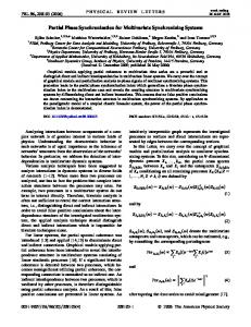
For the best accuracy when synchronizing multiple channels, use a counter or an oscilloscope to measure the phase difference between the channels. Then use the phase adjustment feature in the function generator to “bump” or “hop” the output waveform to align the waveforms. For example, if the output of your function generator is 90° ahead of the signal from your primary function generator, you would enter -90° to cause a one-time shift or “bump” in the signal and align the two generators (see Figure 2). If you are using more than two function generators, repeat this process until all the signals are aligned.
The daisy chain configuration uses a single time base (the master) to provide the input time base signal to the next function generator in the system, which in turn provides a signal to the next successive function generator and so forth until all the function generators are connected. When you use a large number of function generators, the daisy chain configuration provides a simpler method of connecting the time bases. However, the clock skew will increase with every subsequent function generator you add to the chain.
0° Daisy-chain
The output of the function generators will have a random phase relationship at first. Many of today’s function generators, such as the Agilent 33210A, 33220A and 33250A, will allow you to adjust the phase offset in “real time” from the front panel. If your function generator uses a menu structure, look for the phase adjust under an “output” or “setup” menu. (You can find the “output setup” menu for the 33210A, 33220A, and 33250A by pressing the Utility key.)
90° 180° 270°
0°
90° 0°
90° 180° 270°
0°
90°
0°
90° 180° 270°
0°
90°
A.
270°
0°
90° 180° 270°
B.
Star connection (radiating)
FIGURE 2. A) Use the phase adjust to cause a one-time shift or “bump” in the signal. B) This “bump” aligns the output waveforms across multiple generators.
FIGURE 1. Examples of how to connect
the time bases of multiple generators, using the star and daisy chain configurations.
2
MEASUREMENT TIP On some function generators, such as the Agilent 33210A, 33220A, and 33250A, you can set the phase reading to zero without making any changes to the output signal. This is especially useful after you align the outputs of all the generators. Setting the phase reading to zero allows you to then directly set the new phase relationship.
Once you have all the function generators aligned, you can use the phase adjust command again to set a discrete phase offset. For example, if you have three function generators and want to create a three-phase signal, you would “bump” the signal of one generator by 120° and a second by 240°.
Synchronizing to an external event
Hints for synchronizing arbitrary waveforms
Most modern function generators allow the function generator to begin the output of a signal upon receipt of an external trigger signal. On the Agilent 33210A, 33220A, and 33250A function generators, you can use the external trigger with burst mode and set the burst count to “infinite” to initiate the output of a continuous waveform. With this technique, the burst phase is used to set the start phase for each waveform generator.
Synchronizing arbitrary waveforms, such as those used to provide IQ signals, is very similar to synchronizing continuous signals. A few hints to help get you started:
MEASUREMENT TIP Function generators with burst mode offer an alternative means to align your signal. Some function generators, such as the Agilent 33210A, 33220A, and 33250A, allow you to enable a “trigger out” signal that produces a TTL pulse at the beginning of the burst. On the primary generator, set up an infinite burst using the manual trigger source and enable the “trigger out” signal. Set up the other function generators for the infinite burst to begin with an external trigger. Connect the time base output of the primary generator to the other generators, and similarly connect the trigger out of the primary generator to the other generators. When you press the trigger key on the primary generator to start the burst, it will produce an external trigger signal that will begin the burst on all the other generators as well.
3
• When adjusting the phase, the generator will consider the entire arbitrary waveform to be 360°. Adjusting the phase by 90° will shift the arbitrary waveform a quarter of the way through the points. If your arbitrary waveform consists of multiple cycles, adapt your adjustments accordingly. For example, if your arbitrary waveform consists of 2 sine waves and you want the waveform shifted by 90° of one of the sine waves, you need to adjust the phase of the arbitrary waveform by 45°. • Phase relationships may be built into the arbitrary waveform. If the arbitrary waveform includes the phase shift, you will want to align the signals with no additional phase offset to keep the desired phase relationship. • With complex arbitrary waveforms that are running continuously, it is often easier to use the sync signal to align the outputs rather than aligning the arbitrary waveforms themselves. The sync signal acts as a marker within the arbitrary waveform and can be used to align the signals.
Summary Referencing the time bases of function generators allows you to use multiple channels and still maintain a phase relationship between all the channels. Also, by using the equipment you already have and know how to use, you can improve your efficiency. We have reviewed different configurations of the master time base and explored synchronizing multiple signals with a precise phase relationship and synchronizing to an external event using an external trigger. We also showed how a function generator with the right features, such as Agilent’s 33210A, 33220A and 33250A, can simplify the task.
www.agilent.com
FREE – Optional 10 MHz External Time Base Input (Opt 001)
For more information on Agilent Technologies’ products, applications or services, please contact your local Agilent office. The complete list is available at:
www.agilent.com/find/contactus
Link multiple units to create synchronous channels Buy an Agilent 33210A or 33220A and receive the optional 10 MHz external time base input (Option 001) for free – a $395/$495 value. Be sure to mention promotion code 5.744 when you place your order. Hurry, offer ends September 30, 2009 Get details at www.agilent.com/find/FreeOpt001
FREE 1 Opt00 5 $49 $395/ ue val
Learn more about Agilent’s function generator family at www.agilent.com/find/functiongenerators
Product specifications and descriptions in this document subject to change without notice. © Agilent Technologies, Inc. 2009 Printed in USA, March 9, 2009 5990-3467EN