Synthesis of Amorphous Er3+-Yb3+ Co-doped TiO2 for DSSC 3+
Bull. Korean Chem. Soc. 2009, Vol. 30, No. 1
219
3+
Synthesis of Amorphous Er -Yb Co-doped TiO2 and Its Application as a Scattering Layer for Dye-sensitized Solar Cells Chi-Hwan Han,* Hak-Soo Lee, Kyung-won Lee, Sang-Do Han, and Ishwar Singh† Photovoltaic Research Center, Korea Institute of Energy Research, Yuseong, Daejeon 305-343, Korea *E-mail:
[email protected] †Department of Chemistry, Maharshi Dayanand University, Rohtak-124001, India Received August 14, 2008, Accepted October 8, 2008 TiO2 doped with Er3+ and Yb3+ was used for fabricating a scattering layer and a nano-crystalline TiO2 electrode layer to be used in dye-sensitized solar cells. The material was prepared using a new sol-gel combustion hybrid method 3+ 3+ o with acetylene black as fuel. The Er - Yb co-doped titanium oxide powder synthesized at 700 C had embossed structure morphology with a size between 27 to 54 nm that agglomerated to produce micron size particles, as ob3+ 3+ served by the scanning electron micrographs. The XRD patterns showed that the Er - Yb co-doped titanium oxide 3+ 3+ had an amorphous structure, while using the same method without doping Er or Yb , TiO2 was obtained in the crystallite form with thea dominance of rutile phase. Fabricating a bilayer structure consisting of nano-crystalline 3+ 3+ TiO2 and the synthesized Er - Yb co-doped titanium oxide showed better scattering property, with an overall increase of 15.6% in efficiency of the solar cell with respect to a single nano-crystalline TiO2 layer.
Key Words: Dye-sensitized solar cell, Scattering layer, Er3+-Yb3+ co-doped titanium oxide, Amorphous structure
Introduction Since the breakthrough paper by O’Regan and Gratzel, dye-sensitized solar cells have made good progress as an alternative to the conventional silicon-based solar cells because of their low-cost production and high performance.1 These cells efficiently use the dye’s capacity to inject photo-excited electrons into the conduction band of wide band gap nanocrystalline TiO2. However, there are several limitations that restrict the efficiency of the dye-sensitized solar cells, such as (i) particle size of TiO2, (ii) inefficient light absorption by dyes in the near infra-red region, (iii) sub-optimum photovoltage output, (iv) resistance losses, (v) light intensity dependant recombination, (vi) and non-ideal diode dark currents among others. Efforts have led to maximum power conversion under full sunlight to about 10% for a cell with an ac22 tive area of 0.25 cm . The most important part of the cell is TiO2 (nano-crystalline) film, which is size dependent and utilizes more photons 3 due to a larger quantity of adsorbed dye. It has also been suggested that a mixture of submicron-sized particles with nano-crystalline TiO2 or a bilayer structure consisting of light scattering layer and nano-crystalline semi-transparent TiO2 layer can improve photocurrent density instead of using only nano-crystalline TiO2 film.4,5 The idea of using the submicron particles of TiO2 g with nano-crystalline film comes from the fact that light scatters strongly when colliding with the large particles, which increases the path length of the incident light in the nano-crystalline TiO2 film. Here again, the scattering of light is dependent on the size of the TiO2 particles of the supporting layer6 as well as on its refractive index.5 Some workers, therefore, had made efforts towards modifying the TiO2 electrodes.7-13 Kusama et al.14-15 have, however, stressed the incorporation of additives in the electrolytic solutions for in-
creasing the efficiency of the cells, which is another promising area of research. So far as modification of TiO2 electrode is concerned, efficiency of the dye-sensitized solar cells could be enhanced us7 ing WO3, electrophoretic deposition and compression of titania particles,8 incorporating carbon powder,9,10 zirconia,11 ZnO,12 Al2O3-coated SnO2/TiO2 composite13 etc. Recently, up-conversion, in terms of absoption of two or more lower energy photons followed by emission of higher energy photon, of Er3+-Yb3+ co-doped material has attracted much attention 16 because of potential application in optical devices. However, no work has been done for making a TiO2 scattering layer modifying by doping with rare earth elements. We found an improvement in efficiency over 15% if the TiO2 electrode is fabricated with a bilayer consisting of nano-crystalline TiO2 and a synthesized TiO2 material doped with Er3+ and Yb3+. Experimental 3+
3+
Synthesis of Er and Yb co-doped TiO2 powder. Titanium(IV) isopropoxide, erbium(III) nitrate pentahydrate, and ytterbium(III) nitrate pentahydrate were purchased from Aldrich and were used as the starting material. Acetylene black was purchased from the Chevron Phillips Chemical Company. Fig. 1 shows the flow scheme of the combustion 3+ 3+ process used for the synthesis of Er and Yb co-doped TiO2 powder. To the mixture of 2.0 mL acetic acid and 16.0 mL of ethanol, 3.4 mL of titanium isopropoxide and 0.2 g of acetylene black were added to the mixture of 2.0 mL acetic acid and 16.0 mL of ethanol. The sol was stirred for 30 min while 1.0 mL water was added dropwise. Then 0.566 g of erbium(III) nitrate pentahydrate and 0.573 g of ytterbium(III) nitrate pentahydrate were added and the sol was stirred for one more hour.
Bull. Korean Chem. Soc. 2009, Vol. 30, No. 1
Acetylene black Mixed paste D. I. Water Sol-gel process Drying & heat treatment
des were prepared by placing a few drops of 10 mM hydrogen hexachloroplatinate(IV) hydrate (99.9%, Aldrich) and 2-propanol solution on FTO glass (TEC 8/2.3 mm, Pilkington) and o calcining it at 450 C for 2 h. The liquid electrolyte was composed of 0.70 M 1,2-dimethyl-3-propyl-imidazolium iodide (Sanko), 0.10 M LiI (Aldrich), 40 mM iodine (Aldrich), and 0.125 M 4-tert-butylpyridine (Aldrich) in acetonitrile. The photoelectrochemical properties of the prepared dye-sensitized solar cell were measured by using a computer-controlled digital source meter (Potentiostat/Galvanostat Model 273A, EG & G) and a solar simulator (AM 1.5, 100 mW/cm2, Driel) as a light source.
TiO2 powder
3+
3+
Synthesis and characterization of Er -Yb co-doped TiO2 nanopowders. When the dried gel a was heated in a high form crucible, the powder on the inner side of the crucible did not burn well, and the acetylene black remained unburnt. Hence, the dried gel was well dispersed on a boat-type crucible and then heated in a muffle furnace. The DSC/TGA plots of the products obtained by the combustion of the sample are shown in Fig. 2. The dried gel containing Er3+ and Yb3+ showed a broad endothermic peak at o o o o 100 C and three exothermic peaks at 276 C, 369 C and 536 C o as depicted in Fig. 2a. The endothermic peak at 100 C can be attributed to the evaporation of the remaining solvent. The o first exothermic peaks at 276 C may be attributed to the decomposition of the organic materials. The peaks at 369oC and 536oC could be attributed to the formation of titanium oxide
100
(b)
TG
60 40
95
Weight ratio (%)
This precursor was dried at 130oC in an oven for 12 h and then heated at 700oC in a furnace. For comparison purposes, TiO2 powder was also synthesized by the same method without adding the erbium(III) and ytterbium(III) nitrates. The synthesized powders were examined by powder X-ray diffraction (XRD; Rigaku, Ultima Plus diffractometer D/Max 2000). The morphology and size of the particles were investigated by using a field emission scanning electron microscope (FE-SEM; Hitachi, S-4300). Thermal analyses were carried out using a simultaneous thermal analyzer (STA; Scinco, STA S-1500) with a heating rate of 5oC/min. Preparation of TiO2 photoelectrode and Ru(II) dye coating. The TiO2 paste (Ti-nanooxide D, Solaronix) was deposited onto conducting glass with a fluorine-doped stannic oxide layer (FTO, TEC 8/2.3 mm, 8 Ω/쉍, Pilkington) using a screen-printing method. The resulting layer was calcined for 2 h at 470oC in a muffle furnace. This process was repeated three times until a thickness of 15 µm was obtained. The area of the prepared porous TiO2 electrode was 25 mm2 (5 mm × 5 mm). Dye absorption was carried out by dipping the TiO2 –4 electrode in a 4×10 M t-butanol/acetonitrile (Merck, 1:1) solution of the standard ruthenium dye: N719 (Solaronix) for 48 h at 25oC. The photoelectrode was then washed, dried, and immediately used to measure the performance of a solar cell. Scattering layers coating. Scattering layers were prepared with the synthesized Er3+ and Yb3+ co-doped TiO2 powder, 3+ and for comparison purposes, with the TiO2 powder only. Er 3+ and Yb co-doped TiO2 powder and TiO2 powder were dispersed in ethanol using an ultrasonic horn. After sonification, the colloidal suspensions were concentrated using a rotary evaporator and transformed into a screen-printable paste by the addition of ethyl cellulose and terpineol. The prepared scattering layer pastes were deposited onto nano-crystalline TiO2 layer using a screen-printing method. UV-Vis transmission spectra of the dye-adsorbed TiO2 films were measured with UV-Vis spectrophotometer (Lambda 2, Perkin Elmer). Since the transmittance of TiO2 film may be different depending on whether the TiO2 film (scattering layer) is in contact with electrolyte or air, the transmission was measured with a completely fabricated dye-sensitized solar cell, not just TiO2 films on FTO glasses. Photovoltaic characterization. Transparent counter electro-
Results and Discussion
20 90
DTA
0
85
-20 -40
80 -60 75 100
(a)
TG
95
Weight ratio (%)
Figure 1. Process for synthesis of Er3+-Yb3+ co-doped TiO2 amorphous material.
DSC (mW/mg)
Ethanol + Acetic acid
Titanium isopropoxide + Er(NO3)3 + YB(NO3)3
Chi-Hwan Han et al.
60 40 20
90
DTA
0 -20
85
-40
80
DSC (mW/mg)
220
-60 75
0
100
200
300
400
500
600
700
800
o
Temperature ( C)
Figure 2. TG and DTA plots of the dried gels recorded between 30 and 900oC at a heating rate of 5oC/min. (a) Er3+-Yb3+ co-doped TiO2 and (b) TiO2
Synthesis of Amorphous Er3+-Yb3+ Co-doped TiO2 for DSSC
Bull. Korean Chem. Soc. 2009, Vol. 30, No. 1
(a)
((b) b)
Intensity (Arb. Unit)
(b)
221
((a) a)
20
30
40
50
60
70
80
2Θ
Figure 3. SEM images of (a) Er3+-Yb3+ co-doped TiO2 and (b) TiO2, o heat treated at 700 C.
Figure 4. XRD results oof (a) Er3+-Yb3+ co-doped TiO2 and (b) TiO2, heat treated at 700 C.
and the decomposition of acetylene black, respectively. The dried gel without Er3+ and Yb3+ also showed also a broad eno o dothermic peak at 100 C and two exothermic peaks at 380 C, o and 568 C as depicted in Fig. 2b. From the thermal analysis, synthesis temperature was deo termined to be 700 C, the temperature at which acetylene black completely burns out. The color the material when doped with Er3+ and Yb3+ was light pink when heated at 700oC, while the TiO2 had pure white if no material was doped. It was observed that the material obtained after doping with Er3+ and Yb3+ at 700oC was in the amorphous powder (Fig. 3+ 3a). The same material, if prepared without doping by Er 3+ o Yb , changed to crystallites when heated at 700 C (Fig. 3b). Possibly, the doping of Er3+ and Yb3+ ions in the TiO2 crystallites broke the rutile and/or anatase structure before finally converting to the amorphous material. This was confirmed by XRD spectra (Fig. 4), as no crystallite phase was shown by the doped material (Fig. 4a), while the material with the same method of application without doping showed clear crystallites having mixed anatase and rutile phases with the dominance of rutile structure (Fig. 4b). Amorphous structure of Er3+-Yb3+ co-doped titanium oxide may stem from the size difference of the ions between Er3+-Yb3+ and Ti4+. When it is 4+ six coordinated, the ion size of Ti is 0.605 Å, while those of 3+ 3+ Er and Yb are 0.89 and 0.868 respectively.17 As observed by the scanning electron micrographs, the particles of the doped material showed size between 27 to 54 nm with embossed structured morphology that agglomerated to produce micron sized particles. Based on the XRD and SEM studies, it was concluded that the acetylene black burnt slowly up to 670oC preventing and
increase in size of the particles by releasing CO2 gas. For the undoped TiO2 material, a mixed structure of rutile and anatase o phase with 45 ~ 222 nm crystallite size was obtained at 700 C. 3+ 3+ However, the Er -Yb co-doped titanium oxide obtained at 700oC had amorphous particles without any crystalline phase. Fig. 5 shows the radiation spectrum of the TiO2 synthesized by the present method doping with and without Er3+- Yb3+ taken in a light intensity of 100 mW/cm2 and spectral irradiance of AM 1.5. The weak absorption spectrum shows a pale pink color of the material when doping was done. The materials did not show any emission in the green region under the standard conditions of sunlight. This means that the visible-to-infrared 0.5
(b) (a)
0.4
Intensity
0.3
0.2
0.1
0.0 400
500
600
700
800
Wavelength(nm)
Figure 5. Radiation spectrum of (a) Er3+-Yb3+ co-doped TiO2, (b) TiO2 with a light intensity of 100 mW/cm2 and spectral irradiance of AM 1.5.
222
Bull. Korean Chem. Soc. 2009, Vol. 30, No. 1
Chi-Hwan Han et al. Table 1. Photovoltaic performance of dye-sensitized solar cells based on the N719 dye with or without scattering layers
40 35
Transmittance (%)
30
Voc (V)
Jsc (mA)
FF
Efficiency (%)
With scattering layer of 3+ 3+ Er - Yb co-doped TiO2
0.773
18.9
0.615
8.98
With scattering layer of TiO2
0.773
18.4
0.614
8.72
Without scattering layer
0.743
17.1
0.613
7.80
(c)
25
(b)
20 15
(a)
10 5 0 350
400
450
500
550
600
650
700
750
800
Wavelengh (nm)
Figure 6. Transmittance of nano-crystalline TiO2 photoelectrode with (a) scattering layer of Er3+-Yb3+ co-doped TiO2, (b) scattering layer of TiO2, and (c) without scattering layer.
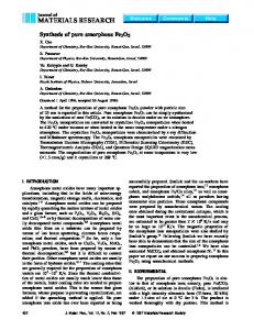
up-conversion luminescence is absent and not utilizing the higher wavelengths for enhancing efficiency. Fig. 6 (a) shows the transmittance of scattering layer produced by Er3+-Yb3+ co-doped TiO2, (b) is a scattering layer of undoped TiO2, and (c) does not have a scattering layer i.e. having a layer of nano-crystalline TiO2 without any supporting layer of TiO2 particles. It was observed that the transmittance increased as wavelength increased. The transmittance is higher when no scattering layer is fabricated, while in comparison to the TiO2 3+ 3+ scattering layer, the Er -Yb co-doped TiO2 layer had minimum transmittance even at higher wavelengths. This shows that the present morphology of the scattering layer is well suited. Effect of light scattering Er3+-Yb3+ co-doped TiO2 layer. The double layer consisting of transparent nano-crystalline 3+ 3+ TiO2 and microcrystalline light scattering Er -Yb co-doped-TiO2 was used for the cell’s photocurrent enhancement. Fig. 7 depicts the photovoltaic curves showing the comparison with TiO2 electrodes fabricated with or without scattering
(a) (b) (c)
Current(mA)
20
15
10
Conclusion
5
0 0.0
layers. The total cell area was kept at 25 mm2. With no light scattering layer in the cell the parameters measured were Jsc = 17.1 mA, Voc = 0.743 V, FF = 0.613 and η = 7.80%. Upon fabrication of the light scattering TiO2 layer without doping any material, the parameters showed enhancement with Jsc = 18.4 mA, Voc = 0.773 V, FF = 0.615, and η = 8.72%, while the scattering layer when made by Er3+-Yb3+ co-doped TiO2 had Jsc = 18.9 mA, Voc = 0.773 V, FF = 0.615, and η = 8.98%. The results relevant efficiency parameters are shown in Table 1. The light scattering layer acts as a photon trapping system and is also active in photovoltaic generation. Rutile and anatase forms of the TiO2 have tetragonal crystal structures possessing high refractive indices (rutile: 2.903; anatase: 2.49); therefore, rutile form has a better scattering property.5 Therefore, people have made efforts based on the idea that a supporting layer of modified crystalline TiO2 of larger particle size might scatter the incident light by colliding with a large particle, resulting in the increase of cell’s efficiency by increasing the path length of the incident light to be made available to the nano-crystalline TiO2 electrode.7-13 In the present case, amor3+ 3+ phous Er -Yb co-doped TiO2 film has a further advantage of having no grain boundary, therefore producing better optical scattering properties16 and since refractive index is closely related to the film density, the packing density of the amorphous TiO2 would be higher than the crystalline forms. This is evident from the results with an overall increase of 15.6% in 3+ 3+ efficiency of the cells when an amorphous Er -Yb co-doped-TiO2 material was used while an increase of 11.7% in efficiency was recorded when undoped TiO2 was used as a scattering layer. This also confirms that if modifications are made in the TiO2 electrode utilizing a bilayer system consisting of both nano-crystalline TiO2 and amorphous Er3+-Yb3+ co-doped-TiO2 material, the efficiency of the solar cells could be increased.
0.1
0.2
0.3
0.4
0.5
0.6
0.7
0.8
0.9
Voltage(V)
Figure 7. Photocurrent-voltage characteristics of solar cells of (a) scattering layer of Er3+-Yb3+ co-doped TiO2, (b) scattering layer of TiO2, and (c) without scattering layer. The measurements were carried 2out at room temperature with a light intensity of 100 mW/cm2, spectral irradiance of AM 1.5, and an active cell area of 0.25 cm .
A new sol-gel combustion hybrid method was utilized that 3+ 3+ offered an effective route for synthesis to prepare Er -Yb co-doped-TiO2. The method produced amorphous powder when doped with Er3+ and Yb3+ and a crystalline rutile and anatase mixed phase, when no doping was performed. Since the Er3+-Yb3+ co-doped-TiO2 material possessed amorphous nature and showed better light scattering as well as lower transmittance properties, it was thus found suitable as a light scattering layer. The light scattering layer increased the efficiency of the dye-sensitized solar cell to by 15.6%.
Synthesis of Amorphous Er3+-Yb3+ Co-doped TiO2 for DSSC References 1. O’Regan, B.; Gratzel, M. Nature 1991, 353, 737. 2. Kroon, J. M.; Bakker, N. J.; Smit, H. J. P.; Liska, P.; Thampi, K. R.; Wang, P.; Zakeeruddin, S. M.; Gratzel, M.; Hinsch, A.; Hore, S.; Wurfel, U.; Sastrawan, R.; Durrant, J. R.; Palomares, E.; Pettersson, H.; Gruszecki, T.; Walter, J.; Skupien, K.; Tulloch, G. E. Prog. Photovolt.: Res. Appl. 2007, 15, 1. 3. Han, C.-H.; Lee, H.-S.; Han, S.-D. Bull. Korean Chem. Soc. 2008, 29, 1495. 4. Ito, S.; Zakeerudin, S. M.; Baker, R. H.; Liska, P.; Charvet, P.; Comte, P.; Nazeeruddin, M. K.; Pechy, P.; Takata, M.; Miura, H.; Uchida, S.; Gratzel, M. Adv. Mater. 2006, 18, 1202. 5. Hore, S.; Vetter, C.; Kern, R.; Smit, H.; Hinsch, A. Sol. Energy Mater. Sol. Cell 2006, 90, 1176. 6. Vargas, W. E. J. Appl. Phys. 2000, 88, 4079. 7. Cheng, P.; Deng, C.; Dai, X.; Li, B.; Liu, D.; Xu, J. J. Photochem. Photobiol. A: Chem. 2008, 195, 144. 8. Grinis, L.; Dor, S.; Ofir, A.; Zaban, A. J. Photochem. Photobiol. A: Chem. 2008, 198, 52.
Bull. Korean Chem. Soc. 2009, Vol. 30, No. 1
223
9. Kang, S. H.; Kim, J.-Y.; Sung, Y.-E. Electrochim. Acta 2007, 52, 5242. 10. Kang, S. H.; Kim, J.-Y.; Kim, Y.-K.; Sung, Y.-E. J. Photochem. Photobiol. A: Chem. 2007, 186, 234. 11. Menzies, D.; Dai, Q.; Cheng, Y.-B.; Simon, G. P.; Spiccia, L. Mater. Lett. 2005, 59, 1893. 12. Kim, S.-S.; Yum, J.-H.; Sung, Y.-E. J. Photochem. Photobiol. A: Chem. 2005, 171, 269. 13. Liu, Z.; Pan, K.; Liu, M.; Wang, M.; Lü, Q.; Li, J.; Bai, Y.; Li, T. Electrochim. Acta 2005, 50, 2583. 14. Kusama, H.; Sugihara, H. J. Photochem. Photobiol. A: Chem. 2007, 187, 233. 15. Kusama, H.; Sugihara, H. J. Photochem. Photobiol. A: Chem. 2006, 181, 268. 16. Shang, Q.; Yu, H.; Kong, X.; Wang, H.; Wang, X.; Sun, Y.; Zhang, Y.; Zeng, Q. J. Lumin. 2008, 128, 1211. 17. Shannon, R. D. Ecta Crysta. 1976, A32, 751. 18. Zhang, M.; Lin, G.; Dong, C.; Wen, L. Surf. Coating Tech. 2007, 201, 7252.