REPORTS
Synthesis of Large Arrays of Well-Aligned Carbon Nanotubes on Glass Z. F. Ren,* Z. P. Huang, J. W. Xu, J. H. Wang, P. Bush, M. P. Siegal, P. N. Provencio Free-standing aligned carbon nanotubes have previously been grown above 700°C on mesoporous silica embedded with iron nanoparticles. Here, carbon nanotubes aligned over areas up to several square centimeters were grown on nickel-coated glass below 666°C by plasma-enhanced hot filament chemical vapor deposition. Acetylene gas was used as the carbon source and ammonia gas was used as a catalyst and dilution gas. Nanotubes with controllable diameters from 20 to 400 nanometers and lengths from 0.1 to 50 micrometers were obtained. Using this method, large panels of aligned carbon nanotubes can be made under conditions that are suitable for device fabrication. Since the first observation of carbon nanotubes (1), numerous papers have reported studies on the yield of well-graphitized nanotubes, their diameter and wall thickness (single or multiple) (2– 4), growth mechanisms (5), alignment (6 – 8), electron emission properties (9 –11), nanodevices (12, 13), theoretical predictions (14), and potential applications (14). Alignment of the carbon nanotubes is particularly important to enable both fundamental studies and applications, such as cold-cathode flat panel displays and vacuum microelectronics. There was little success in obtaining alignment of carbon nanotubes on large areas until the report on the growth of aligned carbon nanotubes on mesoporous silica containing iron nanoparticles via thermal decomposition of acetylene gas in nitrogen gas at temperatures above 700°C (7). However, this high growth temperature makes this method unsuitable for the fabrication of carbon nanotubes on glass because the strain point of the best display glass is 666°C (15). Recently, we have successfully grown large-scale well-aligned carbon nanotubes on nickel foils at temperatures below 700°C (16 ). Here we report the growth of largescale well-aligned carbon nanotube arrays on glass at temperatures below 666°C. These lower temperature growth conditions are suitable for electron emission applications, such as cold-cathode flat panel displays, which require carbon nanotube emitters grown perZ. F. Ren, Z. P. Huang, J. W. Xu, J. H. Wang, Materials Synthesis Laboratory, Natural Sciences Complex, Departments of Physics and Chemistry, and Center for Advanced Photonic and Electronic Materials, State University of New York, Buffalo, NY 14260 –3000, USA. P. Bush, Instrumentation Center, State University of New York, Buffalo, NY 14214, USA. M. P. Siegal and P. N. Provencio, Sandia National Laboratories, Albuquerque, NM 87185–1421, USA. *To whom correspondence should be addressed: Email:
[email protected]
pendicular to the glass surface. The carbon nanotube arrays are fabricated by first depositing a thin nickel layer onto display glass by radio frequency (rf ) magnetron sputtering (17). The carbon nanotubes are then grown on the nickel-coated display glass by plasmaenhanced hot filament chemical vapor deposition (PE-HF-CVD) (17). Scanning electron microscopy (SEM) was used to investigate the effect of various growth conditions on the morphology of car-
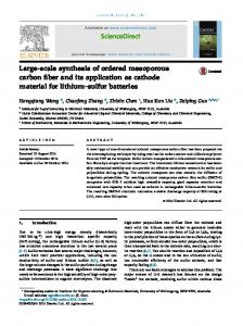
Fig. 1. (A) SEM micrograph of carbon nanotubes aligned perpendicular to the substrate over large areas; growth conditions are listed in Table 1. (B) Enlarged view of (A) along the peeled edge showing diameter, length, straightness, and uniformity in height, diameter, and site density.
bon nanotubes grown on nickel-coated display glass. The growth conditions used are listed in Table 1. In the first experiment, ammonia (NH3) was introduced during the first 5 min without introducing C2H2. During this time, plasma etching was used to reduce the thickness of the nickel layer, resulting in a thickness of ,40 nm. After these initial 5 min, acetylene (C2H2) was introduced. Immediately a color change occurred, as a result of the growth of carbon nanotubes. The growth period lasted only 10 min. In order to examine the orientation and alignment of the carbon nanotubes on the glass substrates, part of the carbon nanotube–covered area was peeled off (Fig. 1A, lower left) with tweezers to expose the glass substrate. During peeling, another area was crumpled (Fig. 1A, lower right), and a long scratch was made on the peeled open area (Fig. 1A, lower left). Under visual and SEM observations, the alignment of the carbon nanotubes across the whole surface was as uniform as in the upper part of Fig. 1A. To estimate the carbon nanotube length, an SEM image was taken at higher
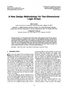
Fig. 2. SEM surface morphology of the nickel layers. (A) Etched by NH3 plasma for 3 min. (B) Etched by N2 plasma for 3 min. (C) As-sputtered smooth surface.
www.sciencemag.org SCIENCE VOL 282 6 NOVEMBER 1998
1105
REPORTS magnification along the peeled edge (Fig. 1B). Misalignment of the carbon nanotubes on the peeled edge is a result of the peeling operation. From Fig. 1B, it was estimated that the nanotubes were about 100 nm in diameter and 20 mm in length. Given the growth time of 10 min, the growth rate was calculated to be 120 mm/hour, which is about five times faster than the value reported in (7). When the sequence of gas introduction was reversed (that is, when C2H2 was introduced first, followed by NH3 5 min later), no growth of carbon nanotubes was observed; only amorphous carbon was formed on the nickel surface under these conditions. The amorphous carbon layer formed in the first 5 min in C2H2 plasma covered the nickel surface and prevented the catalytic role of nickel, so that there was no growth of carbon nanotubes. It seems that the carbon nanotubes grow only when NH3 is introduced first, followed by C2H2, or when both C2H2 and NH3 are introduced at the same time. We conclude that NH3 plays a crucial catalytic role together with the nickel layer to promote the growth of the carbon nanotubes. The catalytic role of NH3 was further confirmed by the fact that there was also no carbon nanotube growth when NH3 was replaced by N2 gas, with the other conditions unchanged. The surface of the nickel layer after the initial NH3 or N2 plasma etching was essentially the same (Fig. 2, A and B, respectively). The plasma etching conditions are listed in Table 1. For comparison, Fig. 2C shows the as-sputtered smooth nickel surface. It is clearly shown that both NH3 and N2 plasma etching roughen the nickel surface, but the roughing of the nickel surface is not responsible for the nucleation and growth of carbon nanotubes. In order to examine the effect of the thickness of nickel layer on the growth of carbon nanotubes, C2H2 and NH3 were introduced at the same time in the second experiment (Table 1). Under these growth conditions, no plasma etching occurred and the nickel layer remained 40 nm thick. The diameters of the carbon nanotubes (Fig. 3A) were much larger than those shown in Fig. 1B. From Fig. 3B, we estimate that the outside diameters of the carbon nanotubes ranged from 180 to 350 nm and that most of the carbon nanotubes were about 250 nm in diameter. This experiment clearly shows that nickel thickness plays a very important role in determining the diameters of the carbon nanotubes. The catalytic role of nickel is also clearly shown by the nickel cap on the tip of each nanotube (Fig. 3B). One carbon nanotube, indicated by an arrow in Fig. 3B, did not have a nickel cap. We conclude that the carbon nanotubes were empty and had very thin walls, because another carbon nanotube is visible behind the capless one through its wall. These large carbon nanotubes may be useful for applications
1106
Fig. 3. (A) SEM micrograph of carbon nanotubes grown as in Table 1. The diameters are clearly larger than those shown in Fig. 1B. (B) Enlarged view of (A) showing the diameters and their distributions. A site density of about 107 tubes/mm2 was estimated. The nickel cap of one nanotube located at the left is missing, as indicated by the arrow. Because the nickel cap is absent, the tube is transparent and the nanotube behind it is visible through the wall.
Fig. 4. (A) SEM micrograph showing that thinner carbon nanotubes were grown on thinner (15-nm) nickel-coated glass. The alignment is not as good as that in Fig. 3B. Growth conditions for this sample are listed in Table 1. (B) SEM micrograph showing carbon nanotubes with diameters as low as 20 nm, grown under the growth conditions listed in Table 1. The image demonstrates that when the nanotube diameters continue to decrease, their alignment is gradually lost.
such as storage of H2 and other gases (18). These experiments show that the thinner the nickel layer, the thinner the nanotubes. To examine further the effect of nickel layer thickness on carbon nanotube growth, another pair of experiments was started with a nickel layer of only 15 nm (Table 1). In one experiment, we again used plasma etching to reduce the nickel thickness by introducing NH3 first and introducing C2H2 20 min later. SEM micrographs of
carbon nanotubes grown under the conditions listed in Table 1 (Fig. 4, A and B) show clearly that the diameters of the nanotubes are dependent on the nickel layer thickness. The typical diameter in Fig. 4A is only about 65 nm, as compared to 240 nm in Fig. 3B. In addition, the alignment in Fig. 4A is not as good as in Fig. 3B. A comparison of Figs. 4A and 4B demonstrates that 20 min of plasma etching reduced the thickness of nickel layer, which in turn
Table 1. Growth conditions for nanotubes as shown in Figs. 1 through 4. C2H2/NH3/N2 (SCCM) Fig. 1, A and B 0/160/0 followed by 80/160/0 Fig. 2A 0/160/0 Fig. 2B 0/0/296 Fig. 3, A and B 80/160/0 Fig. 4A 40/160/0 Fig. 4B 0/160/0 followed by 80/160/0
Filament current (A)
Plasma intensity (A/V/W)
Growth time (min)
8.5 8.5
0.10/635/72 0.13/670/95
5 10
8.5
0.09/740/66
3
8.5
0.10/480/53
3
8.5
0.20/700/150
25
7.2
0.13/650/90
14
8.0 8.2
0.10/480/52 0.10/560/60
20 10
6 NOVEMBER 1998 VOL 282 SCIENCE www.sciencemag.org
REPORTS
Fig. 5. HRTEM images showing the interior and wall structures of a typical thin carbon nanotube. (A) Cross-section view. (B) Plan view.
resulted in even thinner carbon nanotubes with typical diameters of only about 20 nm. The comparison also shows that the alignment starts to worsen drastically when the nanotube diameter is reduced to 20 nm. Therefore, for applications requiring good alignment, diameters should be larger than 50 nm. We used high-resolution transmission electron microscopy (HRTEM) to determine the interior and wall structures of the carbon nanotubes (19). Figure 5A shows a crosssection view of a typical thinner carbon nanotube. The outside diameter of this carbon nanotube is nearly 30 nm. It clearly shows that the nanotube is a multiwalled centrally hollow tube, not solid fiber. The fringes on each side of the tube represent individual cylindrical graphitic layers. This particular carbon nanotube is a structure with approximately 15 walls of graphitized carbon. Both the angular bend in the structure and the appearance of carbon walls running across the diameter of the nanotube demonstrate structural defects suggestive of twisting of the nanotube structure. The lack of fringes inside the tube, as well as the lighter contrast as compared to the nanotube walls, indicate that the core of the structure is hollow.
Further evidence of a hollow core is shown in Fig. 5B. This is a plan view HRTEM image of a single carbon nanotube structure (19). Here we can more clearly see the hollow nature of the nanotube, again represented by the lighter contrast of the inner core. The disorder seen in the wall fringes circumventing the hollow center is most likely caused by the twistlike defects throughout the carbon nanotube length, as shown in Fig. 5A. These HRTEM images definitely show that the structures reported in this paper are hollow multiwalled carbon nanotubes with defects existing along the tube. The defects of bending and twisting of the thin carbon nanotubes shown in Fig. 5, A and B, are consistent with the SEM observation shown in Fig. 4B. The growth mechanism of aligned carbon nanotubes is ascribed in the literature to constraint of the pores in either mesoporous silica (7) or laser-etched tracks (8). However, in our experiments the alignment of the carbon nanotubes cannot be due to pores (7) or etched tracks (8) because there are no pores (7) or etched tracks (8) in our glass substrates, but is rather due to a nanotube nucleation process catalyzed by ammonia and nickel. In the presence of ammonia, each nickel cap efficiently catalyzes the continuous synthesis of carbon nanotubes. As the nanotubes grow, the nickel cap remains on the tip of each. The alignment and thickness of the carbon nanotubes may be determined by the orientation and size, respectively, of the initial catalytic centers. With this method, we can envision the synthesis of large panels of well-aligned carbon nanotubes for use in many applications. 1. 2. 3. 4. 5. 6. 7.
8. 9. 10. 11. 12. 13. 14.
References and Notes
S. Iijima, Nature 354, 56 (1991). A. Thess et al., Science 273, 483 (1996). C. Journet et al., Nature 388, 756 (1997). J. Liu et al., Science 280, 1253 (1998). J. C. Charlier, A. De Vita, X. Blase ´, R. Car, ibid. 275, 646 (1997). W. A. de Heer et al., ibid. 268, 845 (1995). W. Z. Li et al., ibid. 274, 1701 (1996). In this method, the substrate was prepared by a sol-gel process from tetraethoxysilane hydrolysis in iron nitrate aqueous solution. The gel was then calcined for 10 hours at 450°C at 1022 torr. A silica network with relatively uniform pores was obtained, having iron oxide nanoparticles embedded in the pores. The iron oxide nanoparticles were then reduced at 550°C in 180 torr of flowing 9% H2/N2 (110 cm3/min) for 5 hours to obtain iron nanoparticles. The nanotubes grew along the direction of the pores. Only the nanotubes grown out of the vertical pores were aligned. The iron particles on the surface and in the inclined pores resulted in misoriented nanotubes. The alignment was due to the constraint of the vertically aligned pores. M. Terrones et al., Nature 388, 52 (1997). W. A. de Heer, A. Chatelain, D. Ugarte, Science 270, 1179 (1995). A. G. Rinzler et al., ibid. 269, 1550 (1995). Q. H. Wang et al., Appl. Phys. Lett. 72, 2912 (1998). P. G. Collins, A. Zettl, H. Bando, A. Thess, R. E. Smalley, Science 278, 100 (1997). S. Frank, P. Poncharal, Z. L. Wang, W. A. de Heer, ibid. 280, 1744 (1998). T. W. Ebbesen, Carbon Nanotubes: Preparation and Properties (CRC Press, Boca Raton, FL, 1997).
15. L. C. Lapp, D. M. Moffatt, W. H. Dumbaugh, P. L. Bocko, product information, Corning. The display glass substrates used in this paper were supplied by Corning for testing purpose only. Information about the detailed properties can be obtained from Corning. The most important property of the flat-panel display glass is the high strain point of 666°C, as compared to the strain point of 500° to 590°C of commercial glasses. 16. Z. P. Huang et al., in preparation. 17. Before the deposition of the nickel layer, display glass was cut into pieces measuring 10 3 5 mm and then cleaned in acetone by ultrasonication. The cleaned pieces were mounted on the surface of a stainless steel resistive heater, and the whole assembly was introduced into the sputtering chamber. The chamber was then pumped down below 8 3 1026 torr before argon gas was introduced into the chamber to maintain a working pressure of 20 to 60 millitorr. During deposition, the substrates were either heated or kept at room temperature. The deposition of the nickel layer lasted only from 1.5 to 6 min and produced nickel layers from 15 to 60 nm in thickness. After the nickel layers were deposited, the substrates were transferred to a chemical vapor deposition chamber and pumped down below 6 3 1026 torr. As soon as the chamber pressure reached 6 3 1026 torr, acetylene and ammonia gases were introduced into the chamber to maintain a working pressure of 1 to 20 torr during carbon nanotube growth. The total flow rate of acetylene and ammonia gases was 120 to 200 standard cubic centimeters per minute (SCCM), with a volume ratio of acetylene to ammonia varying from 1:2 to 1:10 in different experimental runs. After the working pressure had been stabilized, the power to the tungsten filament coil and that to the plasma generator were turned on to generate heat and plasma. Under the present experimental setup, the temperature of samples is estimated to be below 666°C because there was no visually noticeable change of the glass due to heating. The growth period ran from 5 to 20 min. After growth, the samples were taken out and transferred to a scanning electron microscope (Hitachi S-4000) for examination of nanotube alignment, diameter, length, straightness, site density and uniformity, and so on. Typical samples with good alignment were also examined by x-ray diffraction, Raman spectroscopy, x-ray photoemission spectroscopy and HRTEM to study the structure, crystallinity, composition, central core diameter, and tube wall structures. 18. A. Dillon et al., Nature 386, 377 (1997); G. E. Gadd et al., Science 277, 933 (1997). 19. HRTEM was performed on a JEOL 2010 in the Earth and Planetary Science Department at the University of New Mexico, Albuquerque, NM. Samples for plan view HRTEM were prepared as follows: Given the flexible nature of the nanotubes, we penetrated the films with M-Bond 610 epoxy resin (M-Line Accessories, Raleigh, NC) to provide mechanical stiffness. It has very low viscosity and curing is time and temperature dependent. Hydrotetrafuran (diethylene oxide) makes up about 90% of the composition of M-bond. The carbon nanotube film was immersed in acetone, then M-Bond epoxy was added slowly until a 1:1 ratio was attained. The sample cured at room temperature for 48 hours. The viscosity of the epoxy is very low when introduced to the sample, so it easily impregnates pores and completely mixes with the acetone. Standard mechanical thinning and ion milling (low angle, voltage, and current) were used to thin the sample to electron transparency. Most of the substrate was removed mechanically, followed by ion milling until the film was exposed. Then both sides were ion milled for 15 min. 20. This material is based on work supported in part by the U.S. Army Research Office under contract DAAG55-97-1-0139. The management of this program by R. R. Reeber is greatly appreciated. The authors also thank G. Sagerman for his technical support. Sandia is a multiprogram laboratory operated by Sandia Corporation, a Lockheed Martin Company, for the U.S. Department of Energy under contract DE-AC04-94AL8500. 16 July 1998; accepted 7 October 1998
www.sciencemag.org SCIENCE VOL 282 6 NOVEMBER 1998
1107