Papers dedicated specially to questions concerning the synthesis of signals, for example [16, ...... ing VPs and VCs respectively [35]:. - Fault management: when ...
-1-
Synthesis of Systems Specified as Interacting VHDL Processes Petru Eles1,2, Krzysztof Kuchcinski1, Zebo Peng1
1 Dept.
2
of Computer and Information Science Linköping University Sweden
Computer Science and Engineering Department Technical University of Timisoara Romania
Abstract This paper presents an approach to synthesis of hardware systems specified as interacting VHDL processes. Different from traditional high-level synthesis methodologies our approach takes into account the interactions and interdependence between concurrent processes. Two methods have been developed. The first method supports an unrestricted use of signals and wait statements and synthesizes synchronous hardware with global control of process synchronization for signal update. The second method allows hardware synthesis without the strict synchronization required by the VHDL simulation-based semantics. In both methods VHDL system specifications are first translated into an internal design representation based on timed Petri nets, which is then synthesized into hardware implementation structures at register-transfer level. Our main objective is to preserve simulation/ synthesis correspondence during synthesis and to produce hardware that operates with a high degree of parallelism. Experimental results with practical design examples demonstrate that the proposed methods are efficient in terms of both resulted hardware and optimization time. Keywords: System Synthesis, VHDL, Concurrent Processes, High-Level Synthesis, Process Communication.
This work was supported by the Swedish National Board for Industrial and Technical Development (NUTEK).
-2-
1. INTRODUCTION Complex digital systems are usually specified as a composition of interacting subsystems, each of them described by a sequential process. These processes run concurrently and interact using predefined communication mechanisms. This view of the digital system is usually captured by a system-level description [1, 2, 3, 4]. The complexity of digital systems specified in this way has been growing during recent years and generates a need for new synthesis methodologies/ tools. High-level synthesis (HLS) design methodology has been developed to solve some of these synthesis problems. It accepts the behavioral specification of a hardware at the algorithmic level. This specification describes a sequence of computations to be performed on the input data to produce the required output data. The resulted hardware structure, at RT level, consists usually of a data part controlled by a FSM controller [2, 5]. Current HLS methodology does not solve synthesis problems for digital system specifications consisting of interacting processes and therefore system design environments supporting design features related to process interaction are needed. For example, in addition to traditional HLS allocation and scheduling tasks, new problems like selection of communication strategy, process synchronization structure and hierarchical controller structure must be addressed. Processes have to be considered globally in their interaction structure during system synthesis. This represents an essential distinction from classical high-level synthesis, where one single process is considered at a time. VHDL is a standard hardware description language which is used as a specification language for both simulation and synthesis. Accepting VHDL as the input language for synthesis introduces, however, a lot of additional problems [6, 7, 8]. The main problem is that we have to conform to standard VHDL semantics [9, 10] while avoiding language restrictions that are not acceptable in the context of system specification and synthesis. The HLS community solved this problem by restricting the synthesizable VHDL subset to practically sequential programs with very limited use of signals. This is, however, unacceptable if system synthesis is considered. We have to propose means for efficient synthesis of VHDL concurrent processes together with their underlaying communication structures. Our approach focuses on the synthesis of digital hardware specified as interacting concurrent processes in VHDL. The work is done in two steps. First, we translate concurrent processes into an internal design representation and later synthesis based on this representation is carried out. The main feature of our work, which distinguishes it from other similar approaches, is that we put a special attention to preserve VHDL semantics for a wide subset of the language while synthesizing concurrent processes.
-3-
1.1 Related Work VHDL is already used as an input language for many HLS systems but the language is restricted in many ways. HLS systems usually accept specifications consisting of a single VHDL process and thus only a reduced sequential subset of the language is considered. The use of an explicit clock signal is often imposed, which entails a lower level style of design specification and in some cases requires the designer to make some scheduling decisions. According to SynVHDL [7] and VSYNTH [11], for example, an architecture body may only contain a single process. Silicon 1076 [12] restricts the use of signal assignments to output ports and requires a design to contain only one process described at the architectural level. In CALLAS [13, 14, 15] the designer is required to use one explicit global clock signal. The entire behavior has to be described only in terms of variables, and the use of signals is practically limited to input and output ports. Papers dedicated specially to questions concerning the synthesis of signals, for example [16, 17, 18], do not address the implications for synthesis of signal assignment semantics in the context of a set of interacting VHDL processes either. The need to consider interacting VHDL processes has been recently recognized by the researchers of the HLS community. DSS [19], developed at University of Cincinnati, supports the synthesis of interacting VHDL processes to a synchronous hardware of strongly coupled FSMs with lockstep execution of processes. The synthesis system HIS [20], designed at IBM, accepts interacting processes but imposes several restrictions on the VHDL specification style. It restricts the use of signals to the explicit clock signal in the so called sequential synchronous model. The system accepts only very strictly defined description styles: sequential synchronous model, explicit state machine model, and a dataflow description using only concurrent signal assignments. By imposing these restrictions the global aspects of VHDL process and signal semantics can be avoided. In [21] a method is presented to translate VHDL processes containing signal assignments and wait statements into sequences that can be handled by HLS tools. Signals are replaced by several variables and the resulted processes contain wait statements only on a clock edge. This approach also handles only one single process at a time and the overall synchronization of several VHDL processes is not discussed. Synthesis of concurrent processes, described in HardwareC, and their communication structure is discussed in [22]. The authors concentrate on optimization of communication interfaces which use blocking and non-blocking message passing. Several interface optimization techniques are proposed. In [23] dynamic scheduling and synchronization synthesis for a set of interacting processes is presented. Processes are modeled using a process algebra notation and optimization is performed based on an integer linear programming formulation. 1. 2. Our Approach Our approach is to accept for synthesis system specifications consisting of interacting VHDL
-4-
processes. For a system-level specification restrictions like those imposed by the synthesis systems mentioned above cannot be accepted. The main difficulty is due to those features of VHDL that are explicitly defined in terms of simulation. Keeping simulation semantics during synthesis with a low additional implementation overhead was one of our main objectives. To achieve this goal we compile VHDL in such a way that its essential semantics with respect to process interaction is explicitly captured in our Petri net based internal design representation. The generated synthesis structures are then optimized by high-level synthesis algorithms. Our approach supports two main specification and synthesis styles. The first one accepts an unrestricted use of signals and wait statements. The communication and synchronization mechanism can be defined by using signals and wait statements, as defined by the VHDL standard. This style can be regarded as too low level for system specifications. Hence our second solution is based on higher level communication primitives for synchronous message passing. It is done by defining specialized subprograms for send, receive and test of messages. A similar approach has been proposed independently in [24] for hardware/software co-specification. The solutions we propose have been implemented, and tested with the CAMAD synthesis system [25]. This paper is divided into 7 sections. Section 2 discusses the problems of VHDL simulation semantics and its consequences for synthesis. In section 3 our design environment is briefly introduced. Sections 4 and 5 discuss two methods for VHDL specification and synthesis. They concentrate on representation of VHDL descriptions in extended timed Petri nets representation and further synthesis steps. Finally in section 5 we present some of the experimental results and in section 6 we give conclusions and discuss future work. 2. VHDL AS A SYNTHESIS LANGUAGE VHDL has been defined as a simulation language. Thus, some of the VHDL constructs (access types, files, assert statement) are not significant from the point of view of synthesis. Other features of the language are based on a simulation model and can be only synthesized with some hardware overhead. One of the most difficult issues in this context originates from the way signal assignments and wait statements are defined. As stated in the language definition [9, 10], unlike variables, which are updated as soon as they are assigned a value, signals are only updated at the end of a simulation cycle. This means that the update of signal values must be synchronized with the execution of a wait statement by every process in the system and has to be performed simultaneously for all signals that change their values in that simulation cycle. To illustrate the main problems with VHDL semantics for signal assignment and wait statement, and to draw some conclusions concerning synthesis, we refer to the example in Fig. 1 (we assume that there is no wait statement in processes P1 and P2, except the two given explicitly). Let us consider first only process P1. The value assigned to variable z is the value that has
-5-
. . . signal a, s: integer:= 0; . . . P1: process variable z:integer; . . . begin wait on s; . . . a
+
P3
P3 Out
P3 C1
C1
P6
P4
P1
P5
(a) Control Petri net
C1
C1
(b) Data path ... X := 1; Y := 0; while X>0 loop X := Inp; Y := Y + X; ... end loop; Out := y; ...
--/P0/ --/P7/ --/P2/ --/P3/ --/P4/ --/P5/ --/P6/ --/P1/
(c) VHDL description
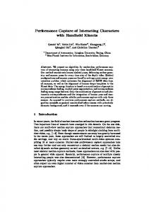
Fig. 2. An example of ETPN representation and its corresponding VHDL description may be fired when it is enabled (all its input places have a token) and the guarding condition is true. If a transition has more than one guarding condition and at least one of them is true, the transition’s guarding condition is true. The ETPN example is generated by CAMAD as the compilation output of the input VHDL specification given in Fig 2(c). The main feature of the ETPN design representation is its ability to capture the intermediate result of a design explicitly so as to allow the design algorithm to make accurate design decisions. For example, if several operations are not data-dependent and can thus be executed concurrently, the situation can be captured precisely by giving their associated control places in the Petri net a potential to hold tokens simultaneously. That is, the set of Petri net places corresponding to the operations will not have any partial ordering relation between them. For example, in Fig. 2, P2 and P7 control the loading of data to register X and Y respectively, which are independent operations. Therefore, P2 and P7 can hold tokens simultaneously. When it is, however, discovered later during synthesis that the potential parallelism will not be able to be implemented (because of resource restrictions, for example), additional partial ordering relations can be introduced. In this case some of the independent operations will be performed in sequence [25]. ETPN is used as a unified design representation which captures the intermediate designs of the
-8-
VHDL Specification VHDL Compiler & Parallelizer
Scheduling Allocation Optimization
ETPN Control Part
Controller Implementation
ETPN Data Path
Simulation and Verification
Netlist Generation
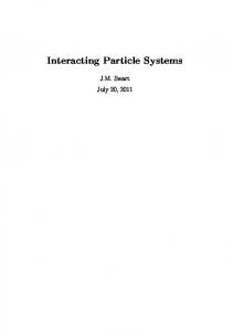
RT-level Design Fig. 3. Overview of CAMAD high-level synthesis process, and thus allows the synthesis algorithm to employ an iterative improvement approach to carry out the synthesis task. The basic idea is that once the VHDL specification is translated into the initial design representation, it can be viewed as a primitive implementation. Correctness-preserving transformations can then be used to successively transform the initial design into an efficient implementation. CAMAD integrates the operation scheduling, data path allocation, control allocation and, to some degree, module binding subtasks of high-level synthesis. This is achieved by developing a set of basic transformations of the design representation which deals simultaneously with partial scheduling and local data path/control allocation. An optimization algorithm is then used to analyze the (global) design and select transformations during each step of the iterative improvement process. Fig. 3 illustrates the basic structure of the CAMAD system. The first step of CAMAD is to map the VHDL specification into ETPN and to perform automatic parallelism extraction. After the transformation steps a RTL hardware implementation is generated which consists of a data path net-list and a controller specified in the form of a finite state machine. The final RTL implementation can be converted into structural VHDL which, as well as the input system specification, can be simulated for verification [26].
-9-
4. SYNTHESIS WITH SIGNAL ASSIGNMENTS AND WAIT STATEMENTS Our approach supports two basic styles for specifying interaction of VHDL concurrent processes: one using Signal Assignments and Wait statements (SAW for short), and the other one based on synchronous Send/Receive message passing primitives (SR for short). The SAW style makes it possible for the designer to express process interaction using signals, as described in the VHDL language definition. From the point of view of synthesis SAW implies the hardware implementation of the synchronization imposed by the simulation cycle. This means that processes have to wait for each other, until all of them are executing a wait statement, in order to update the signal values. The hardware that will be synthesized according to this style is controlled either by a single FSM or by several FSMs working synchronously together. 4.1 Representation of Signals and Wait statements A wait on signal statement is represented in ETPN by associating a condition to a transition in the control part corresponding to the waiting process [27]. The condition will be produced as the result of an assignment to the respective signal. In Fig. 4 we show the ETPN representation of a signal and the control part corresponding to a wait statement. According to ETPN semantics, the process will wait on transition T, until condition CS in the data path becomes true. Signals are modeled by two data path register nodes (s and s’). The value referred by the processes accessing the signal is that in node s while the node s’ stores the last assigned value. Condition CS indicates an event on signal s, and hence will be true only when the new value of the signal differs from the old one. The structure can also be extended to produce the condition corresponding to a transaction on the signal [27]. Updating the signal, by passing the value from node s’ to node s, is controlled by a place, called Q in Fig. 4, that will hold a token only when all processes are executing wait statements (in Fig. 5 we illustrate the control ETPN which contains place Q). The control structure, containing this place, consists of a single FSM or a collection of FSMs, as will be discussed in the following two sections. For reasons of simplicity, in the figures throughout this paper, we use a compressed data path representation for signals depicting only the two register nodes (as, for example, in Fig. 5). wait on s
P s’ Q
Cs
T
s
Q Q
≠
Q
Cs
Fig. 4. Representation of signals and wait statements (model with signal assignment and wait)
- 10 -
4.2 Synthesis of a Collection of State Machines Synthesis of several FSMs, one for each process, is performed on a design representation containing several independent control Petri nets synchronizing through shared data path conditions. In Fig. 5 we present the ETPN structure corresponding to the example discussed in section 2 (Fig. 1). This representation will be generated if the designer requests the synthesis of several FSMs. The supervisor process P0 is automatically generated during compilation of the VHDL description, and is responsible for the synchronized updating of signals, under the control of place Q. This place will be marked only when all processes in the system are executing a wait statement. The required synchronization is achieved by using the one-bit register nodes x1, x2, ..., xk, one for each process Pi in the design. Each node xi is initially reset by the initial place P0. Setting of xi is controlled by any of the places in the respective set of places Ωi, where Ωi consists of all control places corresponding to the wait statements that belong to a process Pi. Node xi will be reset under the control of any place in the set Ωi’, where Ωi’ consists of the places that are direct successors of those in Ωi. In our particular example x1 is set under control of place WP1, and is reset under control of place WP1’ and P0; WP2 controls setting of node x2, and WP2’ with P0 reset the same node. Place α in process P0 does not control any arc. This dummy place indicates that a certain delay
a’
#0
P0
#0
Q
P0
s’ P0
a
Q
s Q
Q
Ca
Pa
Py1
#3 Py1
*
y1 #0
Ω1
Q’
Py2
Pz
y2 #1
x1
WP1
+
Py1
P0 Ω1’
Cs
#10 Pa
Cs
Pa
z
#0
#1
P0 Ω2’
Ω2
x2 Q’
#0
Q’
WP2 C
Ca WP1’
WP2’
Pa
Py1
Pz
Py2
Q
α
#1
P0 Ωk’
xk
Ωk
Q’
and Q’
C Ω1={WP1}, Ω1’={WP1’},Ω2={WP2}, Ω2’={WP2’},...
process P1
process P2
Fig. 5. Design representation for generation of a collection of FSMs
process P0
- 11 -
has to be introduced after signal update, under control of place Q, and before a new evaluation of condition C controlled by place Q’ (both in process P0). This delay is necessary to complete the resetting (controlled by places in the sets Ωi’) of the one-bit nodes xi, corresponding to those processes that are leaving the wait state after signal update. In this way process P0 is forced to stay in state α until all processes leaving a wait state have executed actions controlled by places in sets Ωi’. Thus, all nodes xi, which had to be reset, got their new value before condition C is reevaluated. This means that all processes waiting for an event that has been produced, had the necessary time to leave the wait state before process P0 reaches place Q’ in which it will stay until all processes are again executing a wait statement. The delay assigned to place α will be equal to the clock cycle time if we use a single global clock; if the individual FSMs use their own clock the delay will be equal to the maximum clock cycle time. Since the control Petri nets corresponding to the processes are disjoint, synthesis of a separate state machine for each process is possible. Each Petri net is translated into an FSM by a reachability marking generation algorithm [25]. The algorithm follows the transition firing rules of Petri nets and supports simultaneous firing of several transitions if they are all enabled. The set of FSMs is synchronized by the FSM corresponding to process P0. With the help of the nodes x1, x2, ..., xk in the data path, P0 coordinates the global synchronization so that signals are updated only when all processes are in a wait state. The main advantage of this solution is that the complexity of FSM generation is reduced in comparison to generation of a single FSM for the whole system. However, in this case no data path resources are shared between processes, which may result in a certain hardware overhead. 4.3 Synthesis of One State Machine If the complexity and/or the number of processes are not very large the control structure can be synthesized to a single FSM. This state machine is generated using a design representation that differs from that in Fig. 5. If the designer requests the synthesis of the example in Fig. 1 to a single FSM, the VHDL compiler generates the ETPN structure represented in Fig. 6. Synchronization between waiting processes in order to update signals is moved entirely into the control part where it becomes explicit. The control places Q1, Q2, ..., Qk, one for each process in the system, hold a token only when the corresponding process is executing a wait statement. When all processes are waiting, the transition T can be fired; thus the places Q1’, Q2’, ..., Qk’ will get tokens and the respective signals will be updated. If the condition (Cs or Ca in our particular example) associated to a signal on which a process Pi is waiting becomes true, process Pi will continue (the token is passed from Qi’ to the output place of the transition on which the process was waiting). If the condition associated to the signal is false (the expected event did not happen) Pi enters again its waiting state (the token is passed back from Qi’ to Qi).
- 12 -
P0
a’
#0
P0
#0
Q 1’
s’ P0
a
Q2’
s Q
Q
Ca
Pa
Py1
#3 Py1
#10 Pa
*
+
Py1
Pa
y1
Py2
y2
Pz
Cs
Cs
Ca
Cs
Ca Py1
Pa Q1
z
Q2
T Pz Q1’
Py2
Q2’
process P1
process P2
Fig. 6. Design representation for generation of one FSM For the example illustrated in Fig. 6 we considered only one wait statement in a process. The solution for a general situation, with several wait statements executed by a process, is depicted in Fig. 7. Moving synchronization entirely into the control part increases the complexity of the control Petri net. But this complexity does not entail the generation of a higher number of FSM states. The additional constraints introduced into the control part are made use of by CAMAD to eliminate unreachable states at FSM generation and thus to avoid state explosion.
Cs1
Cs1
Qi
T Cs2
Qi’
Cs2
Fig. 7. Process containing several wait statements
- 13 -
For this solution no “supervisor” process P0 has to be generated and there is no need for the register nodes x1, x2, ..., xk in the data path. The control parts corresponding to the processes are tightly interconnected and thus it is appropriate to generate just one single FSM. Handling the whole representation globally at synthesis for the design of a single FSM allows more control on the allocation of data path elements and offers the possibility of sharing hardware between different processes at synthesis. During the high-level synthesis process, hardware modules can be shared across the process boundaries if the related operations are scheduled into different time steps, which is illustrated by the synthesis results given in section 6. 5. SYNTHESIS WITH SYNCHRONOUS MESSAGE PASSING The synthesis style presented in the previous section entails the implementation in hardware of the global control imposed by the VHDL simulation cycle. Thus it results in a strong synchronization of the processes, that very often exceeds the level needed for the intended functionality of the synthesized system. This oversynchronization is the price payed for an unrestricted use of signals while preserving at the same time simulation semantics at synthesis. The question is if this oversynchronization can be relaxed, allowing a higher degree of parallelism, without giving up simulation/synthesis correspondence. When describing a system in VHDL for simulation, the designer can rely on the definition of the simulation cycle. Our SAW synthesis style guarantees, by implementing the synchronization imposed through the simulation cycle, a similar behavior of the synthesized hardware and of the simulation model. If hardware implementation of the global control imposed by the simulation cycle is not supported, a correct synthesis (as defined by simulation semantics) cannot be guaranteed in general. Such a synthesis approach would update signals and schedule processes without enforcing global synchronization, and thus can produce hardware with a functionality that differs from simulation behavior. Relaxing oversynchronization and preserving at the same time simulation/synthesis correspondence can be solved only under the following assumption: the correct behavior of the VHDL specification to be synthesized should not rely on the implicit synchronization enforced by the simulation cycle. We call a description that conforms to this requirement well synchronized. In a well synchronized VHDL description all the assumptions that provide the proper synchronization and communication between processes are explicitly stated by operations on signals. We will now present a synthesis strategy that does not reproduce the simulation cycle in hardware while maintaining simulation/synthesis correspondence. It accepts designs specified according to a certain description style and produces independent synchronous FSMs which work in parallel. The descriptions conforming to this style are implicitly well synchronized. When defining this specification style we started from the following main considerations:
- 14 -
- It is possible to produce hardware with a high degree of parallelism and asynchrony when the circuit can be described as a set of loosely connected processes. This means that the amount of communication between these processes is relatively low and that a process communicates usually with a relatively small number of other processes. The enforcement of the simulation cycle for this class of hardware can result in a considerable reduction of the potential parallelism (and consequently of the performances) and produces at the same time an increase in hardware complexity. - For the designer, the specification style must be defined through a small number of simple rules that have to be respected for circuit description in VHDL. 5.1 The Designer’s View With the message passing based SR specification style the designer describes hardware as a set of VHDL processes communicating through signals. Any number of processes can communicate through a given signal (we say that these processes are connected to the signal) but only one of these processes is allowed to assign values to it. Assignment of a value to a signal is done by a send command. Processes that refer to the signal will wait until a value is assigned to it, by calling a receive command. Both send an receive have the syntax of ordinary procedure calls. A send command, denoted as send(X, e), where X is a signal, e is an expression, and e and X are type compatible, is executed by a process P in two steps: 1) process P waits until all other processes connected to signal X are executing a receive on this signal (if all these processes are already waiting on a receive for X, then process P enters directly step 2); 2) expression e is evaluated and its value is assigned to signal X. This value becomes the new value of X. After that, process P continues its execution. A receive command, denoted as receive(X), where X is a signal, causes the executing process to wait until a send on signal X is executed. Communication with send and receive can be achieved also through several signals: send(X,e1,Y,e2, ...), where X, Y, ... are signals, and e1, e2, ... are expressions type compatible to the respective signals, solves communication between the executing process and the other processes connected to signal X (that will get the value resulted from evaluation of expression e1), to signal Y (that will get the value resulted from evaluation of expression e2), etc. This communication implies successive synchronization with the respective groups of processes, before assigning the new value to the corresponding signal (according to the rules for simple send and receive); the order of successive synchronizations is not predefined. Execution of the
- 15 -
command terminates after communication on all signal arguments succeeded. receive(X,Y, ...), where all the arguments are signals, causes the executing process to wait until a send on all arguments is executed; synchronization with the sending processes can be realized in any order. The definition of the send/receive commands ensures that between the execution by a process of two consecutive receives on a given signal X, the value of this signal remains unchanged. This is due to the fact that in this interval no send on that signal can become active. This property is very important from the synthesis’ point of view (see section 5.3). To avoid undesired blocking of a process on a receive command (and possible deadlock situations), the boolean function test is provided; test(X), where X is a signal, returns true if there is a process waiting to execute send on X; otherwise the function returns false. Communication with send and receive requires synchronization between processes. However, it is important to note that this synchronization does not necessarily affect all processes but only those involved in a specific communication (the processes connected to a given signal). We illustrate this with the example in Fig. 8. Processes P1 and P3 are connected to signal a; processes P2, P3, and P5 are connected to signal b; Processes P4 and P5 are connected to signal c. When P1 executes the send on a it will synchronize with process P3 that executes a receive on the same signal. P3, for executing send on b, has to synchronize with P2 and P5 that have to execute receive on b. P4 and P5 are synchronized for send respectively receive on signal c. Excepting these restrictions, no other synchronization is required for the correct behavior of the system. A VHDL description corresponding to this style is transformed by a preprocessor into an . . . signal a,b,c: integer; . . . P1: process variable x:integer; . . . begin . . . send(a,x); . . . end process P1; P2: process . . . begin . . . receive(b); . . . end process P2;
P3: process variable y:integer; . . . begin . . . if test(a) then receive(a); y:=a+10; end if; . . . send(b,2*y); . . . end process P3;
P4: process variable z:integer; . . . begin . . . send(c,z); . . . end process P4; P5: process . . . begin . . . receive(b,c); . . . end process P5; . . .
Fig. 8. Example of VHDL processes interacting with send/receive
- 16 -
equivalent standard VHDL model for simulation, by expanding send, receive, and test commands into equivalent sequences containing signal assignments and wait statements. Starting from the same initial description, the VHDL synthesis-compiler generates the ETPN internal representation that will be synthesized by the CAMAD system. Simulation/synthesis correspondence will be preserved during the synthesis process, without providing any synchronization of processes additional to the explicit synchronization required by the send/ receive commands. 5.2 The Simulation Model A VHDL description based on the SR style is translated by a preprocessor to a standard VHDL program for simulation [28]. The generation of the simulation model is solved in two main steps: 1) A package that exports (resolved) bit signals is generated. For each signal X declared by the designer, the package will export the bit signals P1_X, P2_X, ..., Pn_X. Each of these signals corresponds to one of the processes labeled P1, P2, ..., Pn, that execute receive on signal X. The generated signals will be used for implementation of the handshaking protocol between processes. In order to implement the test function, for each signal X that is used as argument of a test, a bit signal t_X will be exported by the generated package. Considering, for instance, the example in Fig. 8, the following package declaration is generated: package p_gen is function res(s:bit_vector) return bit; -- function res implements wired or signal P2_b,P3_a,P5_b,P5_c:res bit:=’0’; signal t_a:bit:=’0’; end p_gen;
2) send and receive commands are expanded, based on predefined templates, to VHDL sequences that implement the handshaking protocol for synchronous message passing between processes connected to the same signals. A reference to function test(X) will be expanded to the boolean expression (t_X = ’1’), and to a wait for 0 statement preceding the statement that contains the reference. The generation of standard VHDL sequences corresponding to operations send and receive, both on one single and on more signals, is presented in [28]. We will illustrate here three such sequences in the context of the example in Fig. 8: a) send(b, 2*y) in process P3 will be expanded to: if P2_b/=’1’ or P5_b/=’1’ then wait until P2_b=’1’ and P5_b=’1’; end if; P2_b