Archive of SID Iranian Journal of Science & Technology, Transaction B: Engineering, Vol. 34, No. B3, pp 235-256 Printed in The Islamic Republic of Iran, 2010 © Shiraz University
SYNTHESIZING A SPECIFICATION-BASED MONITOR * FOR SAFETY REQUIREMENTS S. M. BABAMIR1** AND S. JALILI2 1
Dept. of Computer Engineering, University of Kashan, Kashan, I. R. of Iran Email:
[email protected] 2 School of Electrical and Computer Engineering, Tarbiat Modares University, Tehran, I. R. of Iran Abstract–Safety-critical systems such as medical and avionic ones are the systems in which failure to satisfy the user requirements may put man’s life and resources in jeopardy. Since the adequate reliability of the software of such systems may be unobtainable via formal methods and the software testing approach single-handedly, verification of run-time behavior of software against user requirements violation is considered as a complementary approach. However, the synthesis of such a run-time verifier, hereafter we have called it a monitor, is confronted with the challenging problem of verifying low-level run-time behavior of target software against high-level user requirements violation. To solve this problem, we propose an approach in two phases. In the first phase, we obtain user requirements and then specify their violation formally. This formal specification is a high-level version of user requirements violations and should be mapped to a low-level one. To this end, in the second phase we extract a tabular automaton from the formal specification of user requirements violations in order to determine a state-based specification of the violations. This low-level specification, which constitutes the core of the monitor, determines those states which target software should not reach. To show the effectiveness of our approach, we apply it to the synthesis of a monitor for verifying behavior of the Continuous Insulin Infusion Pump (CIIP) system. Keywords– Safety-critical systems, run-time verification, event-based specification, state-based specification
1. INTRODUCTION Safety-critical systems such as medical, avionic, nuclear reactors and chemical plants are systems that, when they fail, may result in loss of human life or damage to the environment [1, 2, 3]. NASA states, “Software is considered safety-critical if it controls or monitors hazardous or safety-critical hardware or software” [4]. On the other hand, as software becomes an important component of safety-critical systems its size and complexity increases too. This leads to a high probability of the system fault. Therefore, the major aim of safety-critical software development is the development of reliable systems in spite of their complexity. Moreover, the verification and validation process plays a vital role in software development because it is required to ensure that software behaves as intended. The aims of software verification and validation are: (1) exposing the faults of the specification, design, and implementation of the software, (2) assuring software reliability and (3) reducing costs by preventing software failures. Although use of static verification and testing approaches to detect software faults are necessary, they may be inadequate. Using formal methods for static verification is subject to (1) undecidability and difficulty of proving some properties of specifications, and (2) unpredictability of the run-time environment at the specification time. This is why Leucker and Schallhart state that while model checking ∗
Received by the editors May 24, 2008; Accepted June 7, 2010. Corresponding author
∗∗
www.SID.ir
Archive of SID 236
S. M. Babamir and S. Jalili
verification is subject to the infinity of the state space of software runs, run-time verification faces a finite execution of software [5]. Rosu et al showed an experimental case that was generally undecidable, but in run-time verification it was decidable [6]. They state, “We show that although verification of memory safety is in general undecidable, even when restricted to closed, terminating programs, runtime verification of strong memory safety is a decision procedure for this class of programs”. Using software testing is subject to (1) impracticality of testing software by all possible input values (that is why Hoare, Dijkstra [7] and Parnas [8] believe: “Non-exhaustive testing can only show the presence of errors not their absence”) and (2) difficulty of selection of a proper subset of test data. Safety-critical software should be verified properly in order to achieve greater reliability because: (1) there may be some faults left despite verifying specification and testing software, (2) implemented software may be inconsistent with its specification, and (3) the environment in which software will run may be unpredictable. Safety-critical software must be bound to 10-9 failures/hour or less [9], while the reliability growth models have proven that software testing can guarantee 10-4 failures/hour in the best case [10]. In addition, cases such as: (1) codes that a compiler adds to the object code of software, (2) whether a compiler correctly generates an executable code [8], and (3) transient errors such as data corruption and hardware malfunctions are other aspects of the problem. Iyer and Verlardi state that around 10% of software errors and 35% of hardware errors are transient errors, which could not be identified in advance [11]. The above-mentioned problems justify verification of run-time behavior of software against user requirements violation. However, the synthesis of such a run-time verifier, called a monitor is confronted with the challenging problem of verifying low-level run-time behavior of target software against highlevel user requirements because they are not analogous. Since such a monitor is a run-time verifier with a core synthesized based on the specification of high-level user requirements, we call it a specificationbased monitor. To synthesize the monitor, we propose an approach in two phases. In the first phase we obtain user requirements from the problem domain, and then specify their violation of them formally. This phase includes two steps. In the first step, we obtain user requirements from the problem domain via a specific method. In the second step, we represent an event-based specification of violation of user requirements based on interactions between the system and its environment in Event Calculus (EC). EC [12-13] makes three contributions to our approach: (1) it facilitates the specification of the violation of user requirements through a logical and temporal method, (2) it facilitates mapping event-based specification into a statebased one, and (3) it is well-suited to specify user requirements of the safety-critical systems which control and manage their environment based on environment events. The second phase includes two steps as well. In the first step, we extract a tabular automaton from the event-based specification of user requirements violation in order to determine a state-based specification. This specification, which constitutes the core of the monitor, determines those states which target software should not enter. In the second step, we deal with designing the monitor via the State Design Pattern [14], which is a method for designing an automaton. As stated, each phase includes two steps; so we refer to them as steps 1 to 4 where the second and third steps represent two views respectively, event-based and state-based, of a system behavior deviation. Presenting these two views together implies two sides of safety-critical systems behavior: 1) while they are event-oriented in interaction with their environment, 2) are state-based within themselves. We explain the approach in Section 2 and its steps in Sections 3 to 6. In Section 7, in order to show the effectiveness of the approach, we apply each of the steps to derive the monitor of a safety-critical system called Continuous Insulin Infusion Pump (CIIP) [15] from the system problem domain. Finally, in Section 8, we draw some conclusions and we state the features of the approach in comparison with other related approaches. Iranian Journal of Science & Technology, Volume 34, Number B3
June 2010
www.SID.ir
Archive of SID 237
Synthesizing a specification-based monitor for…
2. PRELIMINARIES The run-time verification of software behavior is a lightweight formal method in which no theorem proving method is applied, modeling is restricted; accordingly, mathematics embodiments are reduced. This method uses features of the specification verification and the software testing approaches but unlike them, it just addresses verification of the current execution of software. An execution is a finite sequence of observed program states σ=s1s2…sn where |σ|=n is the length of the execution trace [16]. Leucker and Schallhart state, “Runtime verification deals only with observed executions as they are generated by the real system. An execution of a system is a finite prefix of a run and, formally, it is a finite trace. When running a program, we can only observe executions, which, however, restrict the corresponding evolving run as being their prefix” [17]. This is why the approach does not involve: (1) the complexity of theorem proving methods and state explosion problem of model checking methods and (2) the problem of generating appropriate and sufficient test data to execute software because run-time verification just considers software execution by providing real data originated from run-time environment. The run-time verification approach has shown its effectiveness in comparison with other verification methods [18-20]. Figure 1 shows the architecture of a monitor [21] where the state of executing software changes in response to an environment event. The observer receives the software state and sends it to the analyzer if the state is a concern. Then, the analyzer verifies software states against properties of requirements and gives the result to the event handler. If the current execution of software violates a requirement property, the monitor will react to it through the event handler. In our approach, we assume that: (1) software is a white-box and the observer is a part of the executing software that announces states of interest to the analyzer and (2) the event handler is a part of the analyzer where reaction is a warning message. Therefore, hereafter we refer to the analyzer and event handler in Fig. 1 as the monitor. Legend:
state
Executing software
ellipse: process Requirements
rectangle: data edge: flow of data
Observer state Monitor
Analyzer
state of interests
results of analysis
properties response
Event handler
Fig. 1. Architecture of a monitor [21]
To specify domain-based safety requirements Step 1
To specify formal eventbased safety requirements Step 2
To specify state-based specification of safety requirements Step 3
To design the monitor Step 4
Fig. 2. The proposed approach to derive a monitor from safety requirements
Figure 2 shows the four steps of our approach to synthesize the monitor (i.e., analyzer) which is in charge of current software behavior against violation of user requirements. The user requirements of safetycritical systems are stated as safety requirements. According to [22], a safety requirement asserts, “Nothing bad happens” where the bad event is a violation of a user requirement. Therefore, to monitor a June 2010
Iranian Journal of Science & Technology, Volume 34, Number B3
www.SID.ir
Archive of SID 238
S. M. Babamir and S. Jalili
safety-critical system against safety requirements, run-time behavior of its software should be verified against the user requirements violation. In a medical system, for instance, “Normal pressure” is a user requirement and “Low/high pressure” is a violation of the user requirement. Therefore, the user requirement, “Normal pressure” can be proposed in the form of a safety requirement, “No low or No high pressure should happen” where the low/high pressure is a violation of the user requirement “Normal pressure”. In Step 1, in keeping with the view of the problem domain, we specify safety requirements through determining the violation of user requirements. In Step 2, we present a formal and event-based specification of safety requirements because safety-critical systems are mostly used to control and manage their environment based on the environment events. In Step 3, we consider the event-based specification of the safety requirements violation and derive its state-based specification version. Therefore, the statebased specification shows those states that target software should not enter. In fact, Step 3 is a significant step by which we address the problem of deriving violating low-level run-time behavior from the violation of high-level specifications. In Step 4, we design the monitor based on patterns where each pattern is the state-based specification of a violation. Altogether we present three levels of specification and derive each level from the previous one: (1) domain-based specification, which is a user level one, (2) event-based specification, which is formal and event-based, and (3) state-based specification, which is a low-level one. Accordingly, whenever an environment event happens, the monitor can compare software behavior with the state-based specification of safety requirements violation. Our approach is a systematic one in which the first step is fulfilled manually but the rest of the steps are fulfilled automatically. In the following four sections, we explain the steps of the proposed approach. 3. SPECIFYING DOMAIN-BASED SAFETY REQUIREMENTS (STEP 1) A safety-critical system such as diabetes control system aims at managing a safety-critical environment such as a diabetic where the environment has some requirements. If such a system fails to satisfy the requirements of its environment, the environment may face some disasters. For example, if a diabetes control system fails to satisfy requirement “Normal blood sugar”, the diabetic may be afflicted with cerebral, eye, heart, or kidney diseases. As we stated in Section 2, user requirements of safety-critical systems are stated as safety requirements. In the diabetes system, for instance, “Diabetic’s blood sugar should be normal” is a user requirement that can be stated in the safety requirement, “Diabetic’s blood sugar should not be low or high”. Therefore, to monitor target software its run-time behavior for the violation of the user requirements should be verified. To specify safety requirements, we use problem domain and determine violation of user requirements. Since the problem domain is stated in terms of vocabulary of the system user, it is called domain-based specification. Inspired by [23], in order to determine the violation of the domain-level requirements more naturally and clearly, first we designate an environment by its attributes where an attribute is an important characteristic of the system environment. Afterwards, we define events and invariants in terms of the attributes. Finally, we specify the violation of the user requirements as an event together with some invariants, if any. An event indicates a crucial change in an environment attribute value, but an invariant indicates no crucial change in another attribute value while an event happens. In the diabetes control system, for instance, the diabetic is the system environment where “A sharp fall in his/her blood sugar”, indicated by normal→ low, is the event that violates the user requirement “Normal blood sugar”. However, “A rise in his/her blood sugar”, indicated by normal→ high, is the event
Iranian Journal of Science & Technology, Volume 34, Number B3
June 2010
www.SID.ir
Archive of SID Synthesizing a specification-based monitor for…
239
which violates the user requirement “Normal blood sugar” if the invariant “Insufficient insulin in the system reservoir” holds. In order to define events and invariants formally, we first define data abstraction. a) Data abstraction The system environment is specified by some attributes where an attribute, indicated by Att, is a wellordered set of Boolean, integer or real values. The order property distinguishes the Boolean set {true, false} (with the well-ordering specified by the order of writing its elements) from the Boolean set {false, true}. A well-ordered set is a totally (linearly) ordered set if the set and every one of its subsets contains a first element [24]. For example, the set of integers Z={…-2,-1,0,1,2,…} is a linearly ordered set but not a well-ordered one because it does not have a first element. However, the set of positive integers P={1,2,3,…} is a well-ordered set because P and every one of its subsets has a first element. The order relation “≤” (i.e., “less than or equal”) is a relation on any set Att satisfying the following three properties P1, P2, and P3. P1. Reflexive: for all a ∈ Att, a ≤ a, P2. Antisymmetric: for all a, b ∈ Att, if a ≤ b and b ≤ a then a=b, P3. Transitive: for all a, b, and c ∈ Att, if a≤ b and b≤ c then a≤ c. Definition. A set is said to be bounded if and only if it is a subset of a finite interval. For example, the set { 1n : n ≥ 1 } is bounded because it is certainly a subset of the closed unit interval [0,1] [24]. Let a and b be two distinct integer or real numbers where a < b. An interval with endpoints a and b is defined as a closed-open interval from a to b, i.e., [a,b). Now, based on the problem domain an Att is split up into bounded and disjoint intervals with the order relation “≤” such that for two consecutive intervals, say, [a,b) and [b, c), the supremum of the first interval is the minimum of the second one. In the case of integer numbers, such bounded intervals are finite. However, in the case of real numbers they may be infinite and uncountable. This is not an obstacle to our approach because just the endpoints of each interval are our concerns. Therefore, in the case of real numbers, without loss of generality, we can split an Att up into closed-open intervals such that each interval consists of a minimum and a supremum. For instance, suppose that velocity is the environment attribute whose value reaches 10.0 mph at most and 3.0, 7.5, and 10 are its boundary values. Based on these domain values, we split the velocity up into intervals [0…3.0), [3.0…7.5), and [7.5…10.0]. When an input value is received from the system environment, we compare it with the minimum value of each interval to determine its corresponding interval. Now we deal with the defining properties of intervals on the integer or real attributes: k
Attp = {a0 , a1 , . . . , an} ≡ U Ii,p
// Attp denotes attribute p and it is a well-ordered set. Ii,p is . the ith closed-open interval of Attp (1) I1,p = [a0 , … , aj), . . . , Ik,p = [am , . . . , an): ∀Ii,p ⊂ Real ∨ ∀Ii,p⊂ Integer , i ∈ [1..k] and p is an attribute (2) // each Ii,p is an interval on the Attp whose minimum and ………. supremum are determined based on the problem domain ∀i: Ii,p≠∅ // each interval of an attribute is a non-empty set (3) Ii,p ∩ Ij,p = ∅ : i ≠ j, Ii,p, Ij,p ∈Attp // intervals of an attribute are disjoint (4) a ∈ Ii,p, b ∈ I j,p , i < j a < b { a,b ∈ Ii,p, a < b in Ii,p // because an attribute is a well-ordered set; so each of its ……………….. subset is a well-ordered one [24] (5) i =1
Having determined intervals, we get down to defining interval indicators. Suppose Ii,p is the ith interval of Attp and τ is a sequence number indicating an ordering on the measured values of attribute Attp. An Interval Indicator, indicated by (IIi,p)τ, is a mapping for interval Ii,p at time τ in the form: (IIi,p)τ: (Attp)τ June 2010
Iranian Journal of Science & Technology, Volume 34, Number B3
www.SID.ir
Archive of SID 240
S. M. Babamir and S. Jalili
true|(Attp)τ ∈ Ii,p → { false|otherwise . Hereafter, we call each measuring time of an attribute as an occurrence. Therefore, we say, (IIi,p)τ holds if the τth occurrence of Attp belongs to Ii,p. In the diabetes system, for example, suppose that Att1 indicates the blood sugar attribute; accordingly I2,1 will indicate the second interval of Att1 and expression “(II2,1)3 holds” means, “The third occurrence of the blood sugar belongs to the second interval of Att1”. It should be noticed that at any time, just one interval indicator of an attribute may hold because each value of Attp belongs to just one of its intervals (Relation (6)).
[(IIi,p)τ ∧ (IIj,p)τ] : i≠j, ∀(Ii,p, Ij,p) ∈ Attp, where Attp is an attribute
(6)
b) Event definition We say an event has happened if a change in the value of an attribute such as Attp has caused Attp to change from its Ii,p to the adjacent interval, I(i-1),p or I(i+1),p or vice versa. Accordingly, we have assumed that there would be no sharp change in the value of Attp. Now, we formally define an event. If two consecutive occurrences of Attp, indicated by τth and (τ+1)th belong to two adjacent intervals of Attp, we say an event has happened at time τ. This means that an event has happened when: (1) the τth measured value belongs to I(i-1),p or I(i+1),p and the (τ+1)th measured value belongs to Ii,p or (2) vice versa. The former case is indicated by Relation (7) and the latter case by Relation (8). Relation (7) states, “τ is the last time that Attp has been in I(i-1),p or I(i+1),p and at this time a change in the value of Attp has caused Attp to leave I(i-1),p or I(i+1),p and it then enters Ii,p at τ+1. Similarly, Relation (8) states, “τ is the last time that Attp has been in Ii,p and at this time a change in the value of Attp has caused Attp to leave Ii,p and enters I(i-1),p or I(i+1),p at τ+1. As Relation (7)/(8) shows, we have used just IIi,p. This means that our concern has been just entering/leaving Ii,p not leaving/entering its adjacent interval. (Eventi,p)τ def≡[~(IIi,p)τ ∧ (IIi,p)τ+1]
// entering interval Ii,p at τ+1
(7)
(Eventi,p)τ def≡[(IIi,p)τ ∧ ~(IIi,p)τ+1]
// leaving interval Ii,p at τ+1
(8)
In the case of Boolean (i.e., Att1 = {true, false}), we have a partition, I1,1={true, false} and just an interval indictor, II1,1 is adequate. Therefore, there are just two events: (Event1,1)τ def≡ [~(II1,1)τ ∧ (II1,1)τ+1] (Event1,1)τ def≡ [(II1,1)τ ∧ ~(II1,1)τ+1]
// entering interval I1,1 at τ+1 // leaving interval I1,1 at τ+1
(9) (10)
where, Relations (9) and (10) can be subsumed by Relations (7) and (8). Note that events are mutually exclusive, i.e., there are no concurrent events. In other words, we assume that at most an event happens at each time step. This means that at the value of at most, an attribute changes at each time step (Relations 11 to 14). The left hand sides of Relations 11 to 14 indicate the change of value of Attp at τ and the right hand sides of the relations indicate that there may not be a change in the value of another attribute, say Attq , at the same time. In addition, as we stated in Relation (6), at most, a value of an attribute may change at each time step. if [~(IIi,p)τ ∧ (IIi,p)τ+1] ∧ ∼(IIk,q)τ then ~(IIk,q)τ+1
(11)
if [~(IIi,p)τ ∧ (IIi,p)τ+1] ∧ (IIk,q)τ then (IIk,q)τ+1
(12)
if [(IIi,p)τ ∧ ~(IIi,p)τ+1] ∧ ∼(IIk,q)τ then ~(IIk,q)τ+1
(13)
if [(IIi,p)τ ∧ ~(IIi,p)τ+1] ∧ (IIk,q)τ then (IIk,q)τ+1
(14)
where Ii,p∈Attp, Ik,q∈Attq , p ≠ q Iranian Journal of Science & Technology, Volume 34, Number B3
June 2010
www.SID.ir
Archive of SID Synthesizing a specification-based monitor for…
241
c) Invariant definition Given two consecutive occurrences of Attq, indicated by τth and (τ+1)th, we say there is an invariant on Ij,q if: (1) both occurrences belong to Ij,q or (2) neither of them belongs to Ij,q. We call the former case a true invariant shown as Relation 15 (IIj,q holds) and the latter one a false invariant shown as Relation 16 (IIj,q does not hold). Unlike events, invariants may be concurrent. This means that a combination of true and false invariants may hold at the same time provided each invariant belongs to just a distinct attribute. We show the coexistence of several invariants, i.e. concurrent invariants by ﻩi, r (In i,r ) τ ; this specifies some invariants on intervals of separate attributes; so, for every two concurrent invariants, “(Ini,p)τ” and “(Inj,q)τ”, we have p ≠ q. (Inj,q)τ def≡ [(IIj,q)τ ∧ (IIj,q)τ+1]
// true invariant means, “IIj,q has been true at τ and τ+1” (15)
(Inj,q)τ def≡ [~(IIj,q)τ ∧ ~(IIj,q)τ+1]
// false invariant means, ”IIj,q has been false at τ and τ+1” (16)
d) Domain-based safety requirement As we stated in Sections 2 and 3, a safety requirement indicates that a bad event must not happen where the bad event indicates a user requirement violation. We show the violation as “(Eventi,p)τ ∧ ﻩi, r (In i,r ) τ ”, consisting of an event (Relation 7 and Relation 8) and zero or some true/false invariants (15 or 16). In the diabetes system, suppose that Att1 indicates “blood sugar” whose third interval is the high interval; so, II3,1 indicates, “High blood sugar” and suppose that Att5 indicates “insulin dose” whose first interval is the insufficient interval; so, II1,5 indicates, “Insufficient insulin dose”. Accordingly, “(Event3,1)τ ∧ (In1,5)τ” where (Event3,1)τ is specified as “[~(II3,1)τ ∧ (II3,1)τ+1]”, and (In1,5)τ is specified as “[(II1,5)τ ∧ (II1,5)τ+1]” shows a violation. Invariant “(In1,5)τ” states that at the time of the event, the system reservoir has contained insufficient insulin. In the case of no invariant, a safety requirement will be specified as ~(Eventi,p)τ. In the diabetes system, for example, the statement, “The blood sugar must not fall below normal” indicated by ~(Event1,1)τ is a safety requirement. According to Relations (11) to (14), we assume that there would be no concurrent events. This means that the system would face just one safety requirement at any given time and accordingly the monitor behavior is definite when it is verifying target software behavior in accordance with safety requirements. 4. SPECIFYING EVENT-BASED SAFETY REQUIREMENTS (STEP 2) In Section 3, we specified the user requirements violation at the domain-level as events and invariants. This helped us to provide an abstract event-based specification of user requirements violation. In this section, we intend to map the specification into EC (Event Calculus) Formulae, providing a formal eventbased and time-dependent specification. EC was introduced by Kowalski and Sergot [12] to represent actions in time intervals. EC is based on three domains represented in Fig. 3 where a fluent is a logical variable or a predicate such as “the device is faulty” whose truth-value changes over time and actions, called events change the truth-value of a fluent [25]. A deduction system of EC takes action in terms of time and its effects as input and then produces some facts as output. The actions by Happens, the effects by Initiates, Terminates and Clipped and the facts by HoldsAt are specified. In this paper, we use the Simple EC called SEC [13] in which time points are used rather than time intervals. SEC consists of a main axiom S (Fig. 4) and some predicates (Table 1) [25] where α, β, and τ indicate an action, a fluent, and a time point, respectively. The axiom S states fluent β will be true at time τ if an action (such as α1) happens so that the fluent β is initiated before τ and does not change by the time τ. In order to map the domain-based specifications of the user requirements June 2010
Iranian Journal of Science & Technology, Volume 34, Number B3
www.SID.ir
Archive of SID 242
S. M. Babamir and S. Jalili
violation into SEC formulae, we deal with determining indicators and specifying invariants and events in SEC. 1- τ : time (with algebraic structure and linear ordering relations) 2- Φ = {ϕ1 , ϕ2 , ... , ϕn} ∴ ϕi is a fluent 3- Α = {α1 , α2 , … , αn} ∴αi is an action
S Axiom: HoldsAt(β , τ) ← Happens(α1 , τ1) ∧ Initiates(α1 , β) ∧ τ1 < τ ∧ ~Clipped(τ1 , β ,τ) Clipped(τ1 , β ,τ) ≡ Happens(α2 , τ2) ∧ Terminates(α2 , β) ∧ τ1 < τ2 ∧ τ2 < τ
Fig. 3. Event Calculus domains
Fig. 4. The SEC main axiom S [13] Table 1. SEC Predicates [25]
1 2 3 4 5 6
Predicate Initiates(α,β) Terminates(α,β) τ1 < τ2 Happens(α,τ) HoldsAt(β,τ) Clipped(τ1,β,τ2)
Meaning fluent β starts to hold after action α fluent β stops to hold after action α time point τ1 is before time point τ2 action α occurs at time τ fluent β holds at time τ fluent β stops to hold between τ1 and τ2
a) Determining indicators in EC We consider an interval indicator as a fluent in EC because both are logical variables. Therefore, an attribute consists of a number of fluents. As stated above, facts would be specified as the predicate HoldsAt(β, τ) where β is a fluent. Hence, we can show ~(IIi,p)τ as the predicate “~HoldsAt(IIi,p,τ)” and (IIi,p)τ+1 as the predicate “HoldsAt(IIi,p ,τ+1)” in EC. The predicate “~HoldsAt(IIi,p, τ)/ HoldsAt(IIi,p, τ)” means that the fluent IIi,p, has not held/has held at τth occurrence of the Attp. b) Specifying events According to EC, an event may be represented as its effect on the truth-value of a fluent [25] which corresponds to an interval indicator. We have used this notion throughout this paper. In Section 3.b, we defined an event as Relation (7) or (8 in interval indicators terms. According to Section 4.a, we can represent ~(IIi,p)τ as the predicate “~HoldsAt(IIi,p, τ)” and (IIi,p)τ+1 as the predicate “HoldsAt(IIi,p, τ+1)”; so, we can state Relations (7) and (8) as Relations (17) and (18) respectively. Relation (17) states, “The fluent IIi,p has not held at the τth occurrence of Attp, but it has started to hold at its (τ+1)th occurrence. On the other hand, the main axiom of EC (Fig. 4) states, “A fluent will start to hold if an initiation action occurs”. Therefore, we conclude from Relation (17) that an action has occurred at the τth occurrence of Attp that starts the initiation of the fluent IIi,p at the (τ+1)th occurrence. Now, we represent Relations (11) to (14), indicating no concurrent events, as Relations (19) to (22). These relations state that truth-value of just a fluent can change at any given time. (Eventi,p)τ def≡ [~HoldsAt(IIi,p, τ) ∧ HoldsAt(IIi,p, τ+1)]
// IIi,p has become true at τ+1
(17)
(Eventi,p)τ def≡ [HoldsAt(IIi,p, τ) ∧ ~HoldsAt(IIi,p, τ+1)]
// IIi,p has become false at τ+1
(18)
if [~HoldsAt(IIi,p,τ) ∧ HoldsAt(IIi,p,τ+1)] ∧ ~HoldsAt(IIk,q,τ) then ∼HoldsAt(IIk,q,τ+1)
(19)
if [~HoldsAt(IIi,p,τ) ∧ HoldsAt(IIi,p,τ+1)] ∧ HoldsAt(IIk,q,τ) then HoldsAt(IIk,q,τ+1)
(20)
if [HoldsAt(IIi,p,τ) ∧ ~HoldsAt(IIi,p,τ+1)] ∧ ~HoldsAt(IIk,q,τ) then ∼HoldsAt(IIk,q,τ+1)
(21)
if [HoldsAt(IIi,p,τ) ∧ ~HoldsAt(IIi,p,τ+1)] ∧ HoldsAt(IIk,q,τ) then HoldsAt(IIk,q,τ+1)
(22)
where IIi,p∈Attp, IIk,q∈Attq , p≠q Iranian Journal of Science & Technology, Volume 34, Number B3
June 2010
www.SID.ir
Archive of SID 243
Synthesizing a specification-based monitor for…
c) Specifying invariants In Section 3.c, we defined an invariant as Relations (15) and (16). According to Section 4.a, we can represent them by a combination of predicates “HoldsAt”. Therefore, Relation (15) or (16) is stated as Relation (23) or (24), which state that the truth-value of fluent IIi,p has not changed at two consecutive occurrences of Attp. (Inj,p)τ def≡ [HoldsAt(IIj,p, τ) ∧ HoldsAt(IIj,p, τ+1)] (Inj,p)τ def≡ [~HoldsAt(IIj,p, τ) ∧ ~HoldsAt(IIj,p, τ+1)]
// true invariant in EC
(23)
// false invariant in EC
(24)
d) Specifying safety requirements As we stated in Sections 2 and 3, a safety requirement means that a bad event would not happen where the bad-event is a user requirement violation. A user requirement violation, indicated by “(Eventi,p)τ ∧ ﻩi, r (In i,r ) τ ”, is specified as an event (Relations 23 or 24) and zero or some invariants (Relations 23 or 24). Having specified the violation of a user requirement as “(Eventi,p)τ ∧ ﻩi, r (In i,r ) τ ”, we specify a safety requirement as “(Eventi,p)τ ∧ ~ ﻩi, r (In i,r ) τ ”, indicating a bad event will not happen. In the case of no invariant, we specify the safety requirement as ~(Eventi,p)τ. 5. SPECIFYING STATE-BASED SAFETY REQUIREMENTS (STEP 3) In this section, we aim to present a method by which we map the event-based specification of violations, stated by EC formulae, to the corresponding state-based one. We are thinking of the state-based specification as a tabular automaton (state machine) and we automatically map predicates of EC formulae to the elements of the automaton. Shown in Table 2, the structure of the automaton is influenced by the transition table introduced by “Software Cost Reduction” method [26]. Before mapping the predicates to the elements of the automaton, we explain the syntax and semantic of the automaton. An automaton consists of two distinct sets, state and transition where each state is either an intermediate state or a final one. We use "mode" instead of the state and inspired by [26], we think of a mode as a system state in which the system involves performing an operation. Consider the determination of the dose value in the diabetes system, for instance. The system software should perform the computation operation to determine the value of the dose attribute; so, the "Computing" mode is considered as an operation mode. In Table 2, we have considered: (1) the intermediate modes as safe (normal) operation modes of the system shown by the “Current Mode” column, (2) the final modes as unsafe or critical modes shown by the “Violated Mode” column, and (3) transitions as violations shown by the “Event/Invariant” column. Such a transition moves the system from a normal mode into an unsafe/critical one. To specify the statebased specification of the requirements violation, we should map the event-based one, shown by “(Eventi,p)τ ∧ ﻩi, r (In i,r ) τ ” in Section 4.d to the transitions of the automaton. In fact, each transition causes a requirement violation. As we stated in Section 4.d, a user requirement violation is shown by an event with or without invariants. Therefore, in Table 2 we show the transitions of the automaton as the “Event/Invariant” column and we split the column up into attributes indicated by distinct sub-columns “Attp, p=1..n” (n is the number of attributes). To show the fluents of each attribute, we split the Attp column up into subcolumns indicated by IIi,p. In the “Event/Invariant” column, we show an event as “@T” or “@F” and an invariant as “t” or “f”. “@T” means that the value of the fluent is false in the current mode and becomes true in the violated mode when the transition fires. Similarly, “@F” means that the value of the fluent is true in the current mode and false in the violated mode. “t” means that the value of the fluent is true in the June 2010
Iranian Journal of Science & Technology, Volume 34, Number B3
www.SID.ir
Archive of SID 244
S. M. Babamir and S. Jalili
current mode and remains true when the automaton goes to the violated mode. Similarly, “f” means that the value of the fluent is false in both modes. “x” denotes that the value of the fluent plays no role in firing the transition. Firing a transition indicates the occurrence of a violation and consequently, changes to an unsafe/critical mode. The proposed tabular automaton is deterministic because each transition of the automaton is derived from Relation 17 or 18 and according to Relations (19) to (22), events are mutual exclusive. This means that each transition would have just one "@F/@T"; however, there may be a number of invariants, indicated by "t" or "f", in which each t/f belongs to a distinct attribute. For example, consider the transition “@T f t x” under some fluents of Att1, Att2, Att3, and Att4, respectively. We realize that the system enters an unsafe/critical when, (1) the truth-value of the fluent IIi1 changes from false to true (i.e. an event, denoted by "@T") and (2) the truth-values of the fluent IIj,2 and fluent IIk,3 stay false and true, respectively. Such a specification which shows unsafe or critical (violation) modes, is used to verify run-time system operation modes. In addition, it builds a bridge over the gap between the environment events and the run-time system operation modes to verify run-time behavior of the system in accordance with highlevel domain-based safety requirements. To map the event-based specification of the user requirements violation, stated by the EC formulae into the state-based one, stated by tabular automaton, we have derived ingredients of the automaton consisting of “@T/@F”, “t/f” and “Enter mode IIi,p” from predicates of the EC formulae consisting of compound predicates in Table 3. Now, we deal with verifying the derivations. [~HoldsAt(IIi,p ,τ) ∧ ~HoldsAt(IIi,p ,τ+1)] ≡ "IIi,p = f"
(25)
On the one hand, according to the semantics of the automaton mentioned above, the right hand side of Relation (25) means that the value of IIi,p is false in the current mode and remains false when the automaton goes to its next mode; so, it holds in neither current mode nor the next mode. On the other hand, based on Relation (24), the left part of Relation (25) shows a false invariant (Section 3.c). According to Section 4.c, this means that IIi,p holds at neither the τth nor the (τ+1)th occurrence of Attp. If we think of the system operation as an attribute where each specific operation mode is an occurrence of a system operation, "τ" and "τ+1" will indicate two consecutive system operation modes. Accordingly, the left hand side of Relation (25) means that IIi,p holds in neither the current operation mode (indicated by "τ") nor the next operation mode (indicated by "τ+1"). As a result, relation (25) holds. [HoldsAt(IIi,p ,τ) ∧ HoldsAt(IIi,p ,τ+1)] ≡ "IIi,p = t"
(26)
Relation (26) shows a true invariant that the proof is similar to that of Relation (25). Table 2. The tabular automaton specification automaton of violations Current Mode
Event/Invariant Att1 … Attn
Violated Mode
II1,1 … IIi,1 … II1,n … IIk,n m1
@T / @F / t / f / x …
… mk
… @T / @F / t / f / x …
Unsafe/ Critical … … Unsafe/ Critical …
Table 3. Mapping EC formulae into the tabular Compound predicate (ingredients of violation formulae) 1 [~HoldsAt(IIi,p,τ) ∧ ~HoldsAt(IIi,p ,τ+1)] 2 [HoldsAt(IIi,p,τ) ∧ HoldsAt(IIi,p ,τ+1)] 3 Initiates(α, ΙΙi,p) where α is an action
Type
Transition ingredient invariant IIi,p = f
invariant IIi,p = t event initiate mode ΙΙi,p 4 ~HoldsAt(IIi,p, τ) ∧ HoldsAt(IIi,p, τ+1) event @T(IIi,p) 5 HoldsAt(IIi,p, τ) ∧ ~HoldsAt(IIi,p, τ+1) event @F(IIi,p)
Iranian Journal of Science & Technology, Volume 34, Number B3
June 2010
www.SID.ir
Archive of SID Synthesizing a specification-based monitor for…
[Initiates(α , ΙΙi,p)] ≡ Enter mode ΙΙi,p where α is an action
245
(27)
According to Table 1, predicate “Initiates(α, ΙΙi,p)” asserts, “Event (Action) α initiates fluent IIi,p. Since each system operation mode is an instance of the system action, we can think of the system action as an attribute, say Attp, where "IIi,p" indicates the ith operation mode of the system. This means that “Initiates(α, ΙΙi,p)” indicates initiating a system operation mode. In the diabetes system, for instance, if Attp indicates the system action, "Initiates(Compute, II3,p)" will indicate that the specific action "Compute" initiates the third operation mode of the system action, say the "Computing" operation mode. [~HoldsAt(IIi,p, τ) ∧ HoldsAt(IIi,p, τ+1)] ≡ "@T(IIi,p)"
(28)
On the one hand, the right hand side of Relation (28) states, “IIi,p is false in the normal mode but it changes to true when the system enters its next mode i.e., unsafe/critical mode”. This means, “IIi,p is false in the normal mode but it is true in the unsafe/critical mode”. On the other hand, based on Relation (18), the left hand side of Relation (28) shows an event. According to Section 4.b, this means, “IIi,p does not hold at the τth occurrence of an attribute but it will hold at the (τ+1)th”. In addition, as stated above, the start of every operation mode implies a new occurrence of an attribute; so, we can consider “τ+1” as a new occurrence of an attribute when “τ” indicates its current occurrence. Accordingly, the left hand side of Relation (28) means that IIi,p does not hold in the current mode (indicated by “τ”), but it holds in the next mode (indicated by “τ+1”). As a result, relation (28) holds. [HoldsAt(IIi,p, τ) ∧ ~HoldsAt(IIi,p, τ+1)] ≡ "@F(IIi,p)"
(29)
The proof of Relation (29) is similar to that of Relation (28). To generate elements of the automaton (the last column of Table 3) from the compound predicates (the second column of Table 3), we present an algorithm in Fig. 5 where function “GenerateElement( )” is called for each compound predicate of an EC formulae. The function gets a compound predicate as an input and generates an element of the automaton as an output, i.e. “@T/@F”, “t/f”, and “Enter mode IIi,p”. The automaton, showing the state-based specification of user’s requirements violation, is used to design the run-time monitor. element GenerateElement(cmp: compound) e1, e2, e3, e4, e5: element e1:= “IIi,p=t”, e2:= “@F(IIi,p)”, e3:= “IIi,p=f”, e4:= “@T(IIi,p)”, e5: “Enter mode ΙΙi,p” { p1:= GetPredicate (cmp); // take the first predicate of the compound predicate p2:= GetPredicate (cmp); // take the next predicate of the compound predicate switch (p1) { case “HoldsAt(IIi,p, τ)”: if (p2 =“HoldsAt(IIi,p, τ+1)”) then return e1; if (p2 = “~HoldsAt(IIi,p, τ+1)”) then return e2; case “~HoldsAt(IIi,p, τ)”: if (p2 =“~HoldsAt(IIi,p, τ+1)”) then return e3; if (p2 =“HoldsAt(IIi,p, τ+1)”) then return e4; case “initiates((Eventi,p)τ ,IIi,p)”: then return e5; } // end of switch }
Fig. 5. The algorithm to generate the tabular automaton elements
6. DESIGNING MONITOR (STEP 4) To design the monitor, we deal with the design of a tabular automaton using State Design Pattern. This pattern has already been used for implementing automata [27]. The pattern is suitable for objects whose June 2010
Iranian Journal of Science & Technology, Volume 34, Number B3
www.SID.ir
Archive of SID 246
S. M. Babamir and S. Jalili
behaviors change at run-time [14, 28] i.e., the object behavior depends on run-time events. In addition, the pattern indicates run-time polymorphism i.e., an object behavior is a function of its state. Therefore, we can use the pattern as a method to design the tabular automaton automatically and monitor run-time behavior of software, in accordance with high-level events. The pattern consists of an abstract class and some concrete classes where the former takes the role of an interface and the latter takes the role of a mode. The abstract class includes the signature of methods as well as a method to control switching between concrete classes where concrete classes include the implementation of signatures. We include a signature for each “@T/@F” of the automaton in the abstract class and implement its signatures in the concrete classes. As Table 2 shows, each normal mode may have more than one next state (unsafe/critical) under distinct events. Therefore, a concrete class has as many methods as the distinct events that happen in one mode. Passing from an operation mode of automaton to another one is indicated by switching from a concrete class to another one via the interface. The abstract and concrete classes constitute the monitor program. When an environment event happens, the monitor takes the normal (current) state of target software and the event and switches to the corresponding class using the handler method in the abstract class. In the concrete class, the corresponding method of the event verifies the current state of the target software against the corresponding violations. Then, the monitor issues a warning message of violation if it finds any. For example, to design a monitor based on tabular automaton shown by Table 4, we consider an abstract class and three concrete classes S1, S2, and S3 where S1 consists of two methods (a method for each event) and S2 and S3 consist of one method (Fig 6.). When, for instance, an environment event happens and the target software enters the state S1, the monitor takes the state and switches to class S1 via the state handle method in the abstract class. If the current event is “@T(fluent1)” or ”@F(fluent2)”, the method “fluent1()” or ”fluent2()” in class S1 takes control and verifies invariant “fluent2”/”fluent1” against “f”. Then, the monitor will issue a warning message of violation if it finds a matching case. 7. CASE STUDY: CIIP SYSTEM In this section, to show the effectiveness of our approach, we first introduce the CIIP safety-critical system [15] and then apply the steps of our approach to design a monitor for the system. The system is used for diabetics suffering from “Type 1 Diabetes” called youthful sugar and emerges in all ages, even though children, young people, and ages of before thirty are usually afflicted with the disease [15]. The CIIP system is intended to be worn continuously by a diabetic and the system administers regular doses of insulin based on regular sampling of the wearer’s blood-sugar level. Inspired by [15], we have shown the software faults of the CIIP system consisting of computational, algorithmic, and timing in Fig. A.1 (leaf nodes) in the appendix. In the following subsections, we illustrate the steps of our approach to synthesize a monitor for the CIIP system. a) Specifying domain-based safety requirements When a physician uses the CIIP system to control a diabetic’s blood sugar, he expects, (1) “Blood sugar never falls below 5”, (2) “If blood sugar rises above 5, the system delivers insulin”, and (3) “The delivered insulin dose should be adequate”. According to the physician, blood sugar value varies from 1 to 20. According to the: (1) first requirement, a sugar value below 5 indicates a serious shortfall in blood sugar, (2) second requirement, a sugar value more than 10 indicates excess sugar to be controlled, and (3) third requirement, the delivered insulin dose by the system must be a value not over 6. Among the three mentioned requirements, the violation of the first is critical because it leads to a violent affliction so that the system is not able to cope with it and the violations of the second and the third ones are unsafe but Iranian Journal of Science & Technology, Volume 34, Number B3
June 2010
www.SID.ir
Archive of SID 247
Synthesizing a specification-based monitor for…
remediable. There are two other requirements that are not main requirements of the physician, but are imposed by the physical constraints of the system. The first constraint is that, on the one hand, it is not feasible to sample blood sugar constantly and on the other hand, the sampling should not be excessively delayed. Therefore, the physician suggests 10 minute periods to sample the diabetic’s blood sugar and expects that it should be satisfied by the system. The second constraint imposed by the system is that the reservoir system may have insufficient insulin to deliver; so, existing insulin should be checked at the time of insulin delivery. The violation of both requirements is unsafe because it is reparable. Table 4. A sample automaton specification of violations
Current mode S1 S2 S3
Event/ Invariant @T f f @F x @T @T t
x x x x
Violated mode Unsafe Critical Unsafe Unsafe
State(abstract class) state handler( ); abstract fluent1( ); abstract fluent2( );
S1(Concrete Class) fluent1(){…} fluent2() {…}
S2(Concrete Class)
S3(Concrete Class)
fluent2(){…}
fluent1(){…}
Fig. 6. The class diagram for Table 4
Environment
Diabetic
blood sensor
sample: Att1=start Att2=sugar
H1(t,s)
Att3= time
d
timer
H2(t)
S O F T W A R E M O N I T O R
O
insulin delivery device
Att4=dose
Environment
Diabetic insulin reservoir
Att5= Available H3(Ava)
reservoir indicator
Fig. 7. The CIIP system model
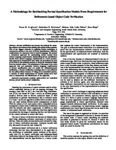
- Modeling system interactions If we consider the above five requirements, we can designate five attributes: “Start of blood sampling” (Boolean), “Sugar value” (sub-range), “The start time of sampling” (time), “Delivered insulin dose” (integer), and “Available insulin” (sub-range), indicated by Att1 to Att5, respectively. Based on the designated attributes, we present a model for the system and its environment (Fig. 7). The system environment is a diabetic and the system components are input, software, and output devices. The timer device sends an interrupt per ten minutes to the input device (blood sensor) to monitor the environment. The insulin delivery unit steered by the software component is an output device to control the diabetic. Therefore, the CIIP system monitors and controls its environment by means of its components. The environment quantity to be monitored is a sample of the diabetic’s blood. The system controls its environment through insulin, whose dose is determined by the software component and delivered by the output device. The sample quantity has two attributes: start of sampling (Att1), and blood sugar (Att2). Furthermore, insulin quantity has dose attribute (Att4). In addition, the system has two local attributes: time (Att3) and available insulin volume (Att5). While the system acquires Att1 and Att2 values from the environment, the environment acquires the Att4 value from the system. The system mission (i.e., main task) is a computation of correct dose value in a timely manner. June 2010
Iranian Journal of Science & Technology, Volume 34, Number B3
www.SID.ir
Archive of SID 248
S. M. Babamir and S. Jalili
-Data abstraction The blood sensor converts Att1 and Att2 to physical value H1(t,s) and the reservoir sensor converts Att5 to physical value H3(Ava), and they then pass the values to the system software component. The software component computes the output value, which is used by the insulin delivery device to determine the value of Att4. The monitor program receives four values H1, H2, H3, and O from the system devices and the current system state from the software component to analyze them in accordance with safety requirements. Based on the problem domain of the CIIP system, we first partition the values of each attribute into some intervals (Column “Intervals” of Table 5) and determine their indicators (Column “Indicators” of Table 5). Consider Att2, for instance; according to the problem domain of the CIIP system, Att2=[1..20] (the second row of Table 5) indicates the set of values of blood sugar where values 5 and 11 denote its boundary values. Accordingly, Att2 is partitioned into three intervals I1,2, I2,2 and I3,2 and logical variables low, normal, and high, indicated by II1,2, II2,2, and II3,2, are considered as their indicators, respectively (the second row of Table 5). Therefore, low, normal, and high are the abstract values that indicate concrete values 1 to 4, 5 to 10, and 11 to 20, respectively. Similarly, according to the problem domain, the attribute Att5=[0..100] (the fifth row of Table 5) indicates available insulin in the system reservoir. The available insulin should not be less than the computed dose. Therefore, the computed dose is a boundary value for Att5. Based on this boundary value, we partition Att5 into intervals I1,5=[0..dose) and I2,5=[dose..100]. Att2 = {1 , . . . , 5 , . . . , 10 , . . . , 20} , I1,2 = [1 , . . . 5) , I2,2 = [5 , . . . , 11) , I3,2 = [11 , . . . , 20] -Specifying events, invariants, and safety requirements Considering Relations (7) and (8) and Relations (15) and (16), we determine events and invariants that violate the user’s safety requirements(Column “Violations” of Table 5). Consider abstraction on the “blood sugar” attribute, indicated by Att2 and its indicators in the second row of Table 5, for instance. Connected with Att2, the requirement “blood sugar must be normal” is violated if blood sugar falls below normal, indicated by (Event1,2)τ=[~(II1,2)τ ∧(II1,2)τ+1] (violation V1,2 in Table 5). In addition, connected with Att2, the invariant (In2,2)τ=[(II2,2)τ ∧ (II2,2)τ+1] violates the requirement if (Event2,4)τ=[~(II2,4)τ ∧ (II2,4)τ+1] happens (violation V2,4 in Table 5) and the invariant (In3,2)τ=[(II3,2)τ ∧ (II3,2)τ+1] violates the requirement if event (Event1,4)τ=[~(II1,4)τ∧(II1,4)τ+1] happens (violation V3,4 in Table 5). Violation V2,4 states that the system was going to deliver insulin while the blood sugar was normal and violation V3,4 states that the system was not going to deliver sufficient insulin while the blood sugar was high. According to Section 3.d, a safety requirement, indicated by Si,p, is represented as ~(Eventi,p)τ if (Eventi,p)τ is a violation; so, connected with V1,2, S1,2=~(Event1,2)τ is a safety requirement. Also, according to Section 3.d, (Eventi,p)τ ∧ ~(Inj,q)τ is a safety requirement if [(Eventi,p)τ ∧ (Inj,q)τ] is a violation; so, connected with V2,4 and V3,4, S2,4=(Event2,4)τ ∧ ~(In2,2)τ and S1,4=(Event1,4)τ ∧ ~(In3,2)τ are two safety requirements, respectively. S1,2 assures that blood sugar has not fallen below normal, S2,4 assures that the system has not delivered insulin when the blood sugar has been normal, and S14 assures that the system has delivered sufficient insulin when the blood sugar has been high. Similarly, we determine events and invariants for other sets and based on these, we specify the violations of the user requirements of the CIIP system (the last column of Table 5). In column “Formulae” of Table 5, the first part of the formulae indicates an event and the second one (if exists) indicates an invariant. According to the problem domain, among the seven violations that we have described in the last column of Table 5, V1,2, V1,4, and V2,4 are critical because they cause blood sugar to fall below 5, leading to irremediable problems, and other violations are unsafe because they lead to reparable problems. Negation of the violations constitutes safety requirements for the CIIP system. Iranian Journal of Science & Technology, Volume 34, Number B3
June 2010
www.SID.ir
Archive of SID Synthesizing a specification-based monitor for…
249
Table 5. Domain-based specification of user requirements violation in the CIIP system p Attp
Type
Intervals
Indicators Name
1
Att1 =[false, true] I1,1= [false], I2,1 = [true] Att2 =[1..20] {1..20} I1,2=[1..5), I2,2=[5..11), I3,2 = [11..20] Att3 = [1..) Integer I1,3= [1..10), I2,3= [10] , I3,3= [11 ..)
Violations Formulae Description [~(II2,1)τ∧(II2,1)τ+1] ∧ Sensor is early in [(~II2,3)τ∧(~II2,3)τ+1] sampling: unsafe Diabetic’s sugar has [~(II1,2)τ ∧(II1,2)τ+1] fallen: critical
II1,1 = idle, V1,1 II2,1 = start 2 II1,2=low, V1,2 sugar II2,2=normal, II3,2=high 3 II1,3=premature, [(II2,3)τ∧(~II2,3)τ+1] ∧ Sensor is late in II2,3= timely, V1,3 time [(~II2,1)τ∧(~II2,1)τ+1] sampling: unsafe II3,3 = belated Pump is going to 4 V1,4 [~(II3,4)τ∧(II3,4)τ+1] deliver overdose insulin: critical Att4 =[0..) II1,4=zero, Pump is going to [~(II2,4)τ∧(II2,4)τ+1] dose Integer I1,4=[0], I2,4=[1..6), II2,4=ordinary, V2,4 deliver unnecessary I3,4 =[6 , . . .) II3,4=over ∧[(II2,2)τ∧(II2,2)τ+1] insulin: critical [~(II1,4)τ∧(II1,4)τ+1] pump delivers short of V3,4 ∧[(II3,2)τ∧(II3,2)τ+1] insulin: unsafe 5 [~(II2,4)τ∧(II2,4)τ+1] Reservoir has Att5=[0..100] II1,5=insufficient insufficient insulin: volume {1..100} V1,5 ∧ I1,5=[0..dose),I2,5=[dose..100] II2,5=sufficient [(~II2,5)τ∧(~II2,5)τ+1] unsafe start
Bool
b) Specifying event-based safety requirements As stated in Section 4, in order to present the event-based specification of safety requirements, we should determine fluents in the CIIP system. According to Section 4.a, we show each interval indicator in the CIIP system as a fluent. Table 6 shows fluents for those indicators of the CIIP system which play a role in the user requirements violation. These appear in column “Formulae” of Table 5. Table 6. Description of used fluents in the CIIP System 1
Fluent start
II II2,1
Description: Value start of sampling: true if started
2
low
II1,2
blood sugar fallen: true if sugar