evaluation of uni-processor computer systems performance is a di cult but well ... is this for parallel processing systems due to the complexity of the internal.
Synthetic Workload Generation for Parallel Processing Systems Hannes Pfneiszl, Gabriele Kotsis Universita t Wien Lenaugasse 2/8, A-1080 Wien, O sterreich [pfneiszljgabi]@ani.univie.ac.at
Abstract. In the performance evaluation for parallel systems, modeling
and generating the workload (i.e. the (set of) programs) is one of the most important and crucial tasks. While benchmarks are frequently used to characterize the real workload in measurement studies, they often fail to adequately describe the real workload, that the analyst has in mind. What is needed is a support for generating synthetic workloads which are on the one hand able to characterize the real workload at the desired level of detail and which are on the other hand easy to construct. In this paper we describe a tool which has been designed and implemented with respect to these demands. The basic idea is to provide a set of communication patterns (e.g. one-to-one, one-to-all) and computation patterns (\tasks"), which are the building blocks of the synthetic program. By \putting" these blocks together, the analyst can create the desired algorithmic structure. This skeleton is the input to an analysis and simulation tool (N-MAP) [Fers 95a]. Within this environment, various quantitative parameters describing the duration of computations and communications can be speci ed. The \execution" of the skeleton is then simulated based on the provided parameter values.
1
Introduction
1.1 Motivation
The term performance evaluation is used in computer science and computer engineering to refer to the set of concepts, methodologies, and tools that are needed to assess the performance of computer systems, hardware and software components of these systems as well as computer programs. Measurement and evaluation of uni-processor computer systems performance is a di�cult but well established discipline since many years. More di�cult and hardly understood is this for parallel processing systems due to the complexity of the internal structure of such a computer system and because of the di�culty of describing and predicting the workload for parallel systems. The basic motivation for the discipline in all of its numerous aspects is the need, both intellectually and practically crucial, to apply the quantitative viewpoint of science and engineering to computer systems and computer programs. Till now, there is no serious workload-independent system performance index for (parallel) computer systems. MIPS (million instructions per second) or
MFLOPS1 (million oating-point operations per second) are measures of either peak CPU power or mean CPU power, where a particular instruction mix is assumed in the latter case. Other indices that might seem to be workloadindependent are in reality measured under well-known and standard benchmarks, and valid only for workloads that are well represented by those benchmarks. Therefore an adequate workload characterization is required in every predicative performance evaluation study. Owing to the diversity of architectural approaches of a multiprocessor, the development of models that can provide a true measure of the "actual\ performance of these machines under workloads of interest can be an extremely complex, if not impossible, problem. Since a multitude of architectural and application parameters jointly determine system performance and the modi cation of some factors a�ects others, it is not feasible to construct an elegant yet tractable analytical model that encompasses all performance e�ects. Nondeterminism present in parallel program execution on parallel processing systems introduces an additional degree of complexity. The inherent dynamic run-time behavior of parallel programs is impossible to capture accurately in analytical models. In the face of the above di�culties, empirical results seem to be an attractive alternative for deriving performance measures. This has led to the use of programs with a prespeci ed workload to characterize and evaluate parallel computer performance, i.e. the benchmarking of parallel processing systems.
1.2 Benchmarking Parallel Processing Systems Benchmarking of high-performance computer systems2 has rightly become an active area of investigation [Mess 90], not to mention controversy. Implicit in every well-known scienti c benchmark is the suggestion that the benchmark somehow captures the essence of many important scienti c computations and applications. Just what are the important scienti c computations and in what sense is their essence represented by a benchmark are questions that are typically at the center of any benchmark controversy. Generally, investigating the performance of a system through benchmarks has three major objectives: 1. provide input for improving the design of future advanced computer architectures 2. permit manufacturers to state the capabilities of their systems in a comparable fashion 3. assess the suitability of a given architecture for a class of applications. Nearly all other objectives, e.g. benchmarks assist designers in optimizing hardware and software, benchmarks give a support when deciding to purchase a For massively parallel processing systems or supercomputers MFLOPS are an insu�cient unit for peak performance rates. In this case, the measuring units are GigaFLOPS (billion oating-point operations per second) or even TeraFLOPS (trillion
oating-point operations per second). 2 See for example [Pfne 96] for a survey.
1
new system, benchmarks will teach programming styles that take advantage of architectural features, etc., are covered by those objectives. Using standard benchmarks (e.g. LINPACK [Dong 95], NAS kernels [Bail 86]) to evaluate machine performance is a widely used practice. Considerable effort has been expended to develop benchmark suites (e.g. the Genesis suite [Geto 93]), that are considered to re ect real workloads. Although benchmarking is an excellent approach for performance evaluation, there are also a number of limitations of using it as an approach to "performance characterization\:
{ Each benchmark is itself a mixture of characteristics, and does not relate to a speci c aspect of machine performance. { They provide no insight as to which components of a given program workload have the potential of being the bottlenecks and to what extent. { It is di�cult to be con dent in the ability of "a few lines of code\ to be rep-
resentative of tens of thousands of lines of codes, particularly if the algorithm implemented is not even used in the workload of the evaluated system.
From the standpoint of the person engaged in the performance evaluation activity, the use of a standard benchmark program su�ers from one signi cant limitation { the lack of control over the workload characteristics of the benchmark. Selecting any standard benchmark as the basis for the performance evaluation automatically establishes an associated program workload that is built into the benchmark structure. Hence, it is not possible to experiment with changing individual parameters in the workload that a�ect performance so as to determine optimal settings for such parameters for a given architecture/application combination. Such selective characterization of performance along controlled performance dimensions is an integral part of the design and implementation of better algorithms and applications. What is needed is a synthetic workload generation to omit the di�culties in connection with the predetermined workloads in benchmarks. These generated synthetic workloads have the advantage that they can be made parametric and hence exible in representing workload characteristics.
1.3 Synthetic Workload Generation In the past few years, synthetic workloads have been used in the evaluation of parallel systems. Some approaches were oriented towards the analysis of particular types of applications (e.g. [Fuji 90]), others were proposed in order to investigate components of a computer system (e.g. in [Bodn 91] distributed le systems are studied, or in [LaRo 92] memory management is analyzed). Some results have been reported in [Cand 92] on using synthetic workloads for studying the performance of concurrent programs (using simulation). This approach is rather static, in that the user has no ability to experiment with different parameters to modify the synthetic workload. An attempt towards a useroriented synthetic workload generation is presented in [Kao 92] and [Roge 93] for the analysis of distributed systems.
In this work, we propose synthetic workload generation for parallel systems as a general method which expediently produces a synthetic workload speci ed by the user rather than performing a single generalized experiment with static and/or predetermined workloads. It provides the building blocks for constructing a workload which closely models the application of particular interest to the investigator and the workload can be used to conduct a series of experiments tailored especially for a speci c application. To a large extent, benchmark programs restrict this in uence a user can have on the execution parameters of a benchmark. This of course is useful to make sure that the results are kept comparable, but the user is bound to a program which probably does not have the same workload as the application he is especially interested in. Giving the user a possibility to describe the behavior of a certain application it should be possible to generate a synthetic workload similar to the described program. To do so two approaches are conceivable:
{ A rst and rather static approach is to create a single program that is able to change its behavior according to the parameters. { Another, more exible approach, which is proposed in this work is to develop a program that makes use of these parameters, too, but also generates di�erent synthetic programs. This means creating a synthetic workload generation program instead of developing a benchmark program itself.
The major advantage of the proposed approach is the fact that special features or complete applications (as shown by the example in Section 3) can be simulated without complete implementation.For example, di�erent kinds of communication patterns can be generated by manipulating parameters for message size and task duration. A user does not have to implement his application program completely to investigate its behavior, rather the behavior of the application can be simulated by only determining the algorithmic (task) structure of the application program. Synthetic programs with selected sets of parameters can be generated and their execution can be simulated on (a model of) parallel systems. By varying the parameters systematically, those factors can be discovered which most a�ect the performance. Generally, the idealized goal for synthetic workload generation is to automatically generate a synthetic workload which mimics the system performance and system behavior of an observed real workload under tunable parameter changes. But using a set of parameters to describe an application is a trade-o� between the two contrary goals of easy usability and model correctness. A large number of parameters makes it easier to create a workload with a behavior closer to the application these parameters are derived from but also makes the synthetic workload program more di�cult to handle. Too few parameters will have opposite e�ects.
2
The Synthetic Workload Generation Facility
The synthetic workload generation facility introduced in this work supports the speci cation, generation, and execution of synthetic workloads on (a model of) parallel systems. It provides the necessary support to e�ciently produce synthetic workloads which are customized for a particular evaluation study. In detail, the synthetic workload generation facility consists of two parts (Figure 1): 1. the synthetic workload generation program SWG [Pfne 96] which generates a user-speci ed synthetic workload and 2. the N-MAP tool [Fers 95a] developed at the Institute of Applied Computer Science and Information Systems to simulate and execute the generated synthetic workloads.
Workload Model
N-MAP
varying workload structure
Synthetic Workload Generator SWG
varying workload parameters
WORKLOAD EXECUTION
WORKLOAD GENERATION
There have been two primary objectives in the design of the synthetic workload generation facility. The rst is to be capable of accurately representing actual workloads. By accurately modeling the structure of the workload, many of the behavioral characteristics can be captured. Representativeness is enhanced by the selection and modi cation of parameters in the workload. Parameters are de ned for both the synthetic tasks and communication packets. These parameters are selected to re ect the properties which are speci c to parallel software. The second goal in the design of the synthetic workload generation facility has been the ease of use. All components of the suite should be easy to use while retaining their exibility and power. Ease of use is enhanced by the simple structure of the synthetic workload generation program and the features provided by N-MAP.
Performance Data
Fig.1. Constituency of the synthetic workload generation facility
2.1 The Workload Model
Generally, a workload model is intended to describe (parallel) workloads in suf cient detail to be used as the basis for generating synthetic workloads. To be an accurate representation of a workload, the model must capture all relevant structural and behavioral details of the workload, since the structure and behavior of the workload a�ect the values of the performance indices that are measured during experiments. Changes in the workload cause changes in the values of the performance indices. Therefore a workload model has to provide a formalism that allows the user to express the connections between the workload, its characteristics, and the measured performance indices. According to these facts, the workload model employed consists of a high level description of the structure of the workload. The N-MAP language provides language constructs for very intuitive notions in parallel programs: tasks, processes and communication packets. In a very abstract sense, a task refers to a contiguous, sequential block of program code. The functionality of a task in a parallel program is referred as its behavior. The quanti cation of its real or expected execution time is expressed with the requirements of a task in units of time. Communication objects, i.e. the actual data to be transferred among (virtual) processors, are referred to as packets. Analogous to tasks, packets are characterized by their behavior and quanti ed by their requirements. At least, an ordered set of tasks de nes a process, seen as a stream of computational or communication task calls. These language constructs are the elements of the basic building blocks of the workload model used by SWG. The blocks (in the following referred to as patterns) can be put together arbitrarily according to the workload structure and timing information can be assigned to the elements of the patterns according to the workload requirements. To see, how the provided patterns t into the proposed workload model, a brief description of each pattern is given.
Computation Tasks Tasks are identi ed by a name given by the users, pro-
cessors are identi ed by numbers ranging from 0 to MAXP-1, where MAXP is an N-MAP parameter, denoting the total number of processors. A task can be assigned to k processors, 1 � k � MAXP . To every task durations can be assigned, deterministic values can be directly speci ed within SWG, more complex expressions can be de ned within N-MAP, which identi es the tasks by the user-de ned names.
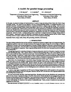
Communication Patterns A variety of prede ned communication patterns are available (schematically depicted in Figure 2) and are discussed below. For every pattern, the data to be exchanged are identi ed by a user de ned name. The \communication volume" (called packet in N-MAP) is de ned in a way analogous to the task durations. Pattern i:K The i:K pattern enables selection of exactly one sending processor i and a set of receiving processors K (1 � jK j � MAXP ). The processor
.... .... (a)
(b)
..
....
....
..
(c)
(d)
.... .... (e)
(f)
Fig.2. General communication patterns i cannot be part of the set of receiving processors K and vice versa. This pattern, called single node broadcast , is depicted in Figure 2(a). For ease of use, the case jK j = MAXP (one-to-all) as well as the case jK j = 1 (pointto-point, depicted in Figure 2(f)), are de ned as additional patterns. Pattern K:i The pattern K : i enables the selection of a set of sending processors K (1 < jK j � MAXP ), each of them performing a send to one receiving processor i, where i 2= K (see Figure 2(b)). Again, the case jK j = MAXP is de ned as a special case, called single node gather. Pattern K:L The pattern K : L enables the selection of a set of sending processors K which make a broadcast to a set of receiving processors L, where jK j; jLj > 1 and K \ L = ;. It can also be called a single node broadcast from every processor 2 K to every processor 2 L. Pattern K:R The pattern K : R enables the selection of a set of sending processors K (1 � jK j < MAXP ) which perform a broadcast to all the remaining processors in R (R = N n K and K \ R = ;). Each processor 2 K performs a single node broadcast to every processor 2 R. The schematic representation is identical for these two patterns and is given in Figure 2(c). Pattern N:K The pattern N : K enables the selection of a set of receiving processors K , each of them receiving a message from all other processors N . This pattern is a gathering performed by a set of nodes, K . The schematic representation is given in Figure 2(d).
Pattern K:K The pattern K : K enables the selection of a set of processors K , where this set is contemporary the set of the receiving processors and jK j � 2 � MAXP . This corresponds to a total exchange or multinode broadcast within a set of K processors and is schematically depicted in Figure 2(e). The special case of jK j = MAXP is called a global exchange where each processor performs a single node broadcast and single node accumulation.
3
Scenario, Walk through
At the current state of implementation SWG is controlled by the user through an interrogatory textual interface. Each possible building block is identi ed by a number, when entering this identi cation number, the program will ask for all the necessary input parameters. The sequence of the blocks is de ned by the sequence in which the numbers are entered. The output of SWG consists of two les. The .tss (task structure speci cation ) le contains the generated program code by SWG and is the input for N-MAP. The le .graph le contains a verbal description of what has been done by the user. It contains the information about the patterns that have been generated, about the processors that have been used, and about the tasks and packets that have been declared. It also contains a simple graphical representation of the generated workload structure. To explain some of the abilities of SWG a simple introductory example will be used. With the communication patterns provided by SWG a butter y communication (see e.g. [Quin 87]) will be generated using 8 processors. This pattern allows a complete exchange of messages among p processors in log p communication steps. Although an all-to-all communication pattern is provided as a default pattern by SWG, the butter y communication pattern may be sometimes more e�cient on a particular architecture (e.g. hypercube) in comparison to the all-to-all communication pattern K:K. The command for starting the program is swg
[SUN]
where is a parameter, de ning the maximum number of processing elements and the parameter SUN is an optional parameter which must be added if the program is used on SunSparc/SunOS 4.1.x. If the program ist started with the parameter help brief information concerning usage of the program (including a brief description of the available patterns) is given. Let us assume, that we have started the program with swg 8 (on an SGI), e.g. we using 8 processors which are numbered from 0 - 7. This is necessary since N-MAP and the visualization tools also use this kind of enumeration. When started, SWG prompts you to enter a name for the program: Enter a name for the program ( = process name):
The program name also determines the process name which is used in the generated synthetic workload program. To create the above stated example the
name butterfly is entered. After entering the name a simple validity check of the name is made. SWG also uses the same directory structures as N-MAP to provide complete support of le manipulation features in N-MAP. The program tests if a program with the entered name already exists. If the name is already used, the user can choose between selecting a (di�erent) new name or creating a new version of the existing program identi ed by a version number (e.g. 1.0). The complete directory structure used by SWG and N-MAP (depicted in [Fers 95b]) is then generated and the program continues displaying the following information on the screen: ################################################################# # # # The following patterns can be chosen (e for end). # # # # b[?]. K processors execute (a) task(s) # # # # 1[t?]. pattern i:K 4[t?]. pattern K:R # # 2[t?]. pattern K:i 5[t?]. pattern N:K # # 3[t?]. pattern K:L 6[t?]. pattern K:K # # # # [Adding 't' enables task selection, adding '?' enables help.] # # # ################################################################# Your selection:
Each of these patterns can be easily selected entering the character stated before the name of the pattern. Note, that pattern b is a computation task, and patterns 1 to 6 represent communication patterns. Since it is typical in parallel programs that a phases of computation are followed by phases of communication, the option t is provided. In that case, the user may enter speci c computation tasks to be executed by the processing elements involved in the communication (see below). The other optional parameter ? provides a brief description and some help on how to use the pattern. The range of the selectable processors for each pattern is 0 �processor �MAXP-1. MAXP is the parameter entered with the program call. Besides, it is possible to repeat each pattern more than one time and there are no limitations in putting together di�erent patterns. Tasks and packets are identi ed by name, e.g. two tasks/packets with the same name are assumed to be identical. This identity will also be used in the simulation (e.g. timings associated to a task/packet will apply to all tasks/packets with the same name). To enhance the recognizability of each task and packet when applying the visualization tool, tasks/packets with identical names are displayed in identical colors. Concerning the option t generally can be said that tasks can be entered before and/or after a broadcast of the sending processor and before and/or after the reception of the broadcast by the receiving processors. If the t option is selected for the pattern K:K, tasks can either be speci ed before the broadcast or after the broadcast (i.e. after every PE has received all messages).
Fig. 3. ParaGraph: Spacetime display of the butter y communication structure with di�erent packet size at each stage
Fig. 4. ParaGraph: Spacetime display of the pattern K:K communication structure Using the patterns de ned in Section 2.1, we can start to generate the program code for the example butterfly. Generally, the butter y communication pattern can be perfectly embedded in the hypercube topology but can even be used (more or less e�ective) on other topologies. To construct the pattern exactly 2k (k �1) processing elements must be available. In this case, the butter y is said to consist of k stages. In each stage, the pattern i:K is used. Note, that in the data transfer, each processor, upon receiving a message, has to add in its own data and forward the enlarged message to the following processors. In our example, the number of processing elements is eight, so the number of stages is three, and the i:K pattern will be used three times, de ning a di�erent packet at each stage which will have a di�erent size. If the user nishes the program SWG, a text editor is called to view the verbal description le butterfly.graph and the program N-MAP is started. When SWG starts N-MAP, N-MAP contains automatically the last generated synthetic workload program by SWG. In our case, the program butterfly is loaded. All settings concerning scenarios and cases have been made by SWG with default values so that the user does not have to make any necessary parameter settings. Without making any changes, the user can press the Simulate button in N-MAP to start parsing/translating, compiling, and simulating the synthetic
program. When simulation is nished, the execution trace can be visualized using di�erent kinds of ParaGraph displays (e.g. spacetime displays as in Figure 3 and 4). The main di�erence of the two patterns is the fact, that the butter y structure uses di�erent packets at each stage, whereas the K:K pattern uses the same packet continuously. To vary the workload for the butter y program and to experiment with di�erent packet sizes, only a few settings have to be changed in N-MAP. Many case studies concerning this rather easy synthetic workload program using di�erent workloads could be stated at this time. But since each user is particularly interested in his individual workload parameter settings they are not of general concern and are omitted. A more complex example using SWG can be found in [Pfne 96]. 4
Conclusions
In this paper, we have presented a new technique for synthetic workload generation for parallel systems. The basic idea is to provide a set of computation and communication patterns from which the structure of the synthetic workload can be composed. These patterns can either be used to mimic a typical application (e.g. the butter y communication structure presented in this paper), or to represent a stress case for the system. Once the structure of the workload has been described, the parameters associated to the duration of computation and communication tasks can be speci ed. These parameters may either be chosen to represent realistic estimates or to represent extremal values. A tool has been developed (Synthetic Workload Generator) to support the speci cation of the workload structure. In the current implementation, the tool has a textual interface, where the user is prompted to enter the desired patterns. To further improve the usability of the tool, a graphical interface is under design. In this graphical environment, the user could put together the building blocks using direct manipulation. Although SWG has turned out being appropriate for a few examples (see [Pfne 96], an e�ort to model the workload of a complex real parallel application has not been attempted until now. Improvements concerning the user-interface (see above), the scalability and code-reusability are possible prospects for future work. References
[Bail 86] D. H. Bailey and J. T. Barton. \The NAS Kernel Benchmark Program". Tech. Rep., Numerical Aerodynamic Simulation (NAS) Systems Division, NASA Ames Research Center, June 1986. [Bodn 91] R. R. Bodnarchuk and R. B. Bunt. \A Synthetic Workload Model for a Distributed System File Server". Performance Evaluation Review, Special Issue, 1991 ACM SIGMETRICS, Vol. 19, No. 1, pp. 50{59, May 1991.
[Cand 92] R. Candlin, P. Fisk, L. Phillips, and N. Skilling. \Studying the Performance of Concurrent Programs by Simulation Experiments on Synthetic Programs". Performance Evaluation Review, Special Issue, 1992 ACM SIGMETRICS, Vol. 20, No. 1, pp. 239{241, June 1992. Poster Session of Extended Abstracts. [Dong 95] J. J. Dongarra. \Performance of Various Computers Using Standard Linear Equations Software". Tech. Rep. CS-89-85, University of Tennessee and Oak Ridge National Laboratory, November 1995. [Fers 95a] A. Ferscha and J. Johnson. \Evaluation of Accuracy/Cost-Tradeo�s in the N-MAP Environment". Tech. Rep. D3H-4 (GZ 308.926), University of Vienna, PACT Consortium, June 1995. [Fers 95b] A. Ferscha and J. Johnson. \Implementation of Workload Characterization Tools: The N-MAP Environment". Tech. Rep. D3H-3 (GZ 308.926), University of Vienna, PACT Consortium, June 1995. [Fuji 90] R. M. Fujimoto. \Performance of Time Warp under Synthetic Workloads". In: D. Nicol, Ed., Distributed Simulation. Proceedings of the SCS Multiconference on Distributed Simulation, pp. 23{28, Society for Computer Simulation, San Diego, California, 1990. Simulation Series, Volume 22, Number 1. [Geto 93] V. S. Getov, A. J. G. Hey, R. W. Hockney, and I. C. Wolton. \The GENESIS Benchmark Suite: Current State and Results". In: Performance Evaluation of Parallel Systems, PEPS'93, November 29-30, 1993, Warwick, UK, pp. 182{190, University of Warwick, 1993. [Kao 92] W.-I. Kao and R. K. Iyer. \A User-Oriented Synthetic Workload Generator". In: Proceedings of the 12th International Conference on Distributed Computing Systems, pp. 270{277, IEEE Computer Society Press, Los Alamitos, California, 1992. [LaRo 92] R. P. LaRowe, C. S. Ellis, and M. A. Holiday. \Evaluation of NUMA Memory Management Through Modeling and Measurements". IEEE Transactions on Parallel and Distributed Systems, Vol. 3, No. 6, pp. 686{701, Nov. 1992. [Mess 90] P. Messina, C. Bailie, P. Hipes, J. Rogers, A. Alagar, A. Kamrath, R. Leary, W. Pfei�er, R. Williams, and D. Walker. \Benchmarking advanced architecture computers". Concurrency: Practice and Experience, Vol. 2, No. 3, pp. 195{255, Sep. 1990. [Pfne 96] H. Pfneiszl. Synthetic Workload Generation for Parallel Processing Systems. Master's thesis, University of Vienna, Institute of Applied Computer Science, January 1996. [Quin 87] M. J. Quinn. Designing e�cient algorithms for parallel computers. McGraw-Hill International Publishers, New York, 1987. [Roge 93] S. A. Rogers. \A Synthetic Workload Generator for Evaluating Distributed Fault-tolerant Environments". Tech. Rep. ESL-AFT-040-93, MCC, 1993.
This article was processed using the LTEX macro package with LLNCS style