System and Circuit Considerations for Low-Complexity Constant-Envelope FM-UWB John F.M. Gerrits1,2, Mina Danesh2, Yi Zhao2, Yunzhi Dong2, Gerrit van Veenendaal3, John R. Long2, and John R. Farserotu1 1
CSEM SA, CH2007 Neuchâtel, Switzerland, email:
[email protected], Delft University of Technology, Mekelweg 4, NL2628CD Delft, The Netherlands, 3 IC Lab, NXP Semiconductors, High Tech Campus 46, NL5656AE Eindhoven, The Netherlands. 2
Abstract — Low-complexity, low power UWB radios are required for low data rate short-range applications. FM-UWB is a constant-envelope UWB communication system using double FM: digital FSK followed by high modulation index analog FM to create a constant-envelope signal. The system is intended for low data rate (< 250 kbps), short-range (< 10 m) personal area network (PAN) systems. Due to its simple architecture and relaxed hardware specifications, FM-UWB radio has the potential for low power consumption which is illustrated using two circuit implementation examples. Index Terms — low complexity, low power, low data rate, LDR, wireless personal area networks, PAN, UWB, FM-UWB, VCO, LNA.
I.
INTRODUCTION
Ultra-wideband (UWB) communications systems are poised to play an increasingly important role in today’s short-range communications systems, especially in personal area (PAN) and body area network (BAN) applications. UWB systems have demonstrated greater robustness than traditional narrowband schemes to frequency-selective multipath and interference. The low transmit power of UWB radios extends operating time from a single battery and eases coexistence with existing wireless communication systems. Originally, UWB systems used impulse radio and a timedomain approach [3]. Today’s standard for high data-rate UWB specifies multi-carrier OFDM [4], which provides robust connections for bit rates from 55 to 480 Mbit/s. This high-performance system yields good energy/bit performance, but at the expense of circuit complexity and power consumption [5, 6].
978-1-4244-5309-2/10/$26.00 ©2010 IEEE
New wireless applications such as health monitoring and body-area networks (BAN) require tetherless connectivity at data rates below 250 kbps, a range less than 10 m, and operational lifetime from a single battery charge of weeks or months. In addition, cost and size constraints envisioned for short-range applications require low-complexity RF interfaces. FM-UWB [1, 2] targets this level of performance, using a low-complexity implementation based upon wideband analog FM. The IEEE802.15 Task Group 6 (IEEE802.15.6) is currently developing a BAN communication standard [7], where FM-UWB is a candidate for low data rate, medical BAN applications operating in the 7.2 GHz-9.5 GHz band. The full (PHY-MAC) proposal [8] combines FM-UWB radio with an energy efficient, high availability protocol called WiseMAC [9]. Section II of this paper describes the FM-UWB radio architecture and performance. Section III addresses the hardware implementation. It presents two examples of low power circuit implementations. II.
CONSTANT-ENVELOPE FM-UWB
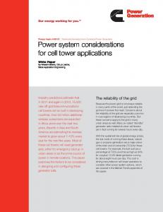
FM-UWB is an analog implementation of a spread-spectrum system that targets short range (1-10m) applications with bitrates up to 250 kbps using a simple and robust modulation scheme and straightforward circuit implementations. Fig. 1 shows the block diagram of a FM-UWB transmitter that implements double FM; that is, low modulation index digital FSK is followed by high modulation index analog FM, thereby creating a constant-envelope UWB signal [2].
3300
Fig. 1.
FM-UWB transmitter block diagram.
Fig.3.
The transmitter comprises a 1-2 MHz subcarrier oscillator generating a triangular signal m(t) that is FSK modulated by the transmit data. Direct digital synthesis (DDS) techniques are used for subcarrier generation. The subcarrier signal m(t) modulates the RF VCO, yielding a constant-envelope UWB signal with a flat power spectral density and steep spectral roll-off as illustrated in Fig. 2. The RF oscillator is modulated open loop, and the transmitter center frequency is calibrated periodically using a PLL. The receiver demodulates the FM-UWB signal without frequency translation (i.e., no mixing) as shown in Fig. 3. A LNA and wideband FM demodulator constitute the RF frontend. Direct-conversion to baseband is used for the subcarrier filtering an demodulation (see Fig. 4) to relax the filter specifications FM-UWB is an analog implementation of a spread-spectrum system with processing gain (GPdB) equal to the ratio of RF and sub-carrier bandwidth ⎛ B G PdB = 10 log 10 ⎜⎜ RF ⎝ B SUB
⎛ 2Δf RF ⎞ ⎞ ⎟ ⎟ = 10 log 10 ⎜ ⎜ (β ⎟ ⎟ ⎝ SUB + 1)R ⎠ ⎠
(1).
In a 250 kbit/s LDR system with 500 MHz RF bandwidth, a processing gain of 30 dB is obtained. The despreading performed by the wideband FM demodulator is instantaneous, and the synchronization in the receiver simplifies to simple bit synchronization, as in narrowband FSK receivers.
Fig. 2.
FM-UWB receiver block diagram.
FM-UWB signals are robust to frequency-selective multipath in BAN operating scenarios. It was found that 2.8 dB of fading margin is required to achieve 99% availability in the 802.15.6 CM3 channel (body-surface to body-surface) and only 1.7 dB of fading margin is required in CM4 (bodysurface to external device) [8]. A narrowband radio requires 20 dB higher received power for 99 % availability (assuming a Rayleigh fading channel).
III.
HARDWARE IMPLEMENTATION EXAMPLES
The hardware implementation of the FM-UWB transceiver is potentially very low power and low cost compared to other wireless schemes, because of relaxed oscillator phase noise requirements in the transmitter (-80 dBc/Hz at 1 MHz offset) and the absence of a local oscillator in the receiver. A FM-UWB transceiver prototype operating in the 7.2 – 7.7 GHz band based upon 3 full-custom ICs, has been developed and tested [10]. Receiver sensitivity is -85 dBm for a BER of 10-6 at 62.5 kbps, with a range of 15 meters under LOS conditions. Estimated power consumption for a fully integrated (i.e., single chip) version is 1 mW for the transmitter and 5 – 8 mW for the receiver. The following sub-sections present two low-power circuit implementation examples of the FM-UWB radio: a 7 – 8.5 GHz VCO and output stage for the transmitter and a 7.45 GHz high-gain and low-noise preamplifier for the receiver front-end.
Fig. 4.
Spectrum of FM-UWB signal at 7.45 GHz.
3301
Receiver subcarrier processing.
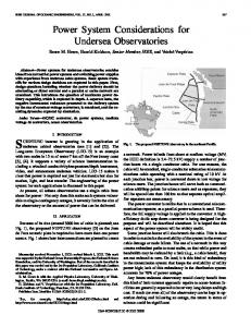
A. A 7 – 8.5 GHz RF VCO and Output Stage Fig. 5 shows a low power VCO with 1.5 GHz tuning range around a center frequency of 7.75 GHz. It includes an output stage which directly drives a loop antenna. The circuit has been designed in a 90 nm CMOS together with a number of lower frequency VCOs. [12].. A differential LC oscillator is implemented by cross-coupled NMOS pair M1-M2. The parallel resonant LC tank is formed by the primary winding of transformer T1 and NMOS varactor Cv1. In order to obtain low supply voltage operation (VDD = 600 mV), transistor gate lengths of 150 nm are used with a threshold voltage of 430 mV. VCO transistors M1 and M2 operate at the verge of threshold; VB is chosen to be 380mV, and VG is 880 mV. Transistors M3 and M4 operate in triode, limiting the isolation of the buffer stage to 10 dB. Supply current is shared by both the oscillator and buffer stages. This configuration minimizes the power consumption and eliminates the need for a current source. L2 and Cv2 constitute a parallel resonant LC tank tuned to the FM-UWB center frequency. Inductor L2 is a small loop antenna. No additional matching network is required, and the VCO chip may be connected via flip chip to the loop antenna to minimize parasitic effects. Its simulated supply current is 700 μA which yields 420 μW of DC power consumption. RF output power is 40 μW (-14 dBm) at 7.75 GHz. Phase noise is -90 dBc/Hz at 1 MHz offset across the band, which is sufficient for the FM-UWB application. B. A 7.45 GHz Low Noise Amplifier Fig. 6 shows the schematic of a high-gain LNA implemented in a 0.25 μm SiGe:C-BiCMOS technology used in a FMUWB transceiver prototype [13]. The active balun input stage consists of common-base (Q1) and common-emitter (Q2) stages both biased at 1 mA and with inputs connected in parallel. This configuration yields an almost pure differential output signal (0.1 dB amplitude and 0.5° phase errors). Collector shot noise from transistor Q1 is cancelled in the differential output as the voltage gains in each path are set equal in magnitude. A second differential CE stage (Q3 – Q4) is cascaded with the input stage to obtain 30 dB gain. The Miller effect in both stages is neutralized by feedback capacitors implemented by transistors Q5 – Q8. The bias current of the second stage is reused in the input stage to lower power consumption.
Fig. 5 LC VCO and output stage [12].
Parallel resonant circuit LL1-Ct1 (Fig. 6) provides a high impedance AC load for the first stage, while capacitors Cc1 and Cc2 AC couple the two stages. LL1 conducts bias current from transistors Q3 and Q4 to transistors Q1 and Q2. The 25Ω input impedance of Q1 is transformed to 50Ω by a passive network consisting of bondwire, package lead and circuit board trace. An electrical model for the package was developed for this design using Ansoft’s Q3D Extractor® tool [14]. On-wafer measurements show that the preamplifier has a voltage gain of 31.5 dB, noise figure of 5.7dB at 7.5GHz, -17 dBm input 3rd order intercept point, while consuming a total of 2 mA from a 1.8 V supply. The noise figure drops to 4.5dB when the circuit is properly packaged. IV.
CONCLUSIONS
Low-complexity FM-UWB technology based upon analog spreading and despreading techniques has the potential to deliver robust low power, low cost UWB radios. A full transceiver prototype has demonstrated feasibility of the concept for applications such as body-area networking.. Estimated power consumption for a fully integrated (i.e., single chip) version is 1 mW for the transmitter and 5 – 8 mW for the receiver.
3302
Fig. 6.
7.45 GHz, 30 dB preamplifier schematic [13].
REFERENCES [1] John F.M. Gerrits, John R. Farserotu and John R. Long, "Low-Complexity Ultra Wideband Communications", IEEE Transactions on Circuits and Systems-II, Vol. 55, No. 4, April 2008, pp. 329 - 333. [2] J.F.M. Gerrits, M.H.L. Kouwenhoven, P.R. van der Meer, J.R. Farserotu, J.R. Long , "Principles and Limitations of Ultra-Wideband FM Communications Systems," EURASIP Journal of Applied Signal Processing, vol. 2005, no. 3, pp. 382-396, March 2005. [3] M. Z. Win, R.A. Scholtz, "Impulse Radio: How It Works, " IEEE Communications Letters, vol.2,no. 2, pp. 36-38, 1998. [4] G.Heidari, WiMedia UWB: Technology of Choice for Wireless USB and Bluetooth. New York: JohnWiley & Sons, 2008. [5] J. Ryckaert, e.a., "Ultra-wide-band Transmitter for LowPower Wireless Body Area Networks: Design and Evaluation" , IEEE T. Circuits and Systems I, Volume 52, Issue 12, Dec. 2005 pp. 2515 – 2525. [6] R. Roovers, e.a, "An Interferenc-Robust Receiver for UltraWideband Radio in SiGe BiCMOS Technology," IEEE J. Solid-State Circuits, Vol. 40, No. 12, December 2005, pp. 2563 – 2572. [7] Body Area Networks (BAN), IEEE 802.15 WPAN™ Task Group 6, [Online]. Available: http://www .ieee802.org/15/ pub /TG6.html.
[8] John Farserotu, e.a., " CSEM FM-UWB Proposal," IEEE P802.15 Working Group for Wireless Personal Area Networks (WPANs), 4 May 2009, doc.:IEEE802.15-09-027600-0006, [Online]. Available: https:// mentor.ieee.org/802.15/ dcn/09/15-09-0276-00-0006-csem-fm-uwb-proposal.pdf. [9] A. El-Hoiydi and J.-D. Decotignie, "WiseMAC: An ultra low power MAC protocol for multi-hop wireless sensor network," in Proc. ALGOSENSORS 2004, pp. 18 – 31. [10] J.F.M. Gerrits, H. Bonakdar, M. Detratti, E. Pérez, M. Lobeira, Y. Zhao, Y. Dong, G. van Veenendaal, J.R. Long, J. R. Farserotu, E. Leroux and C. Hennemann, "A 7.2 – 7.7 GHz FM-UWB Transceiver Prototype," in Proc. ICUWB2009, pp. 580 - 585. [11] John F.M. Gerrits, John R. Farserotu, and John R. Long, "Multipath Behavior of FM-UWB Signals," in Proc. ICUWB2007, pp. 162 - 167. [12] Mina Danesh and John R. Long, "Ultra-low Power Transmitters for UWB-FM Sensor Networks," in Proc. ProRISC2008, pp. 166 – 170. [13] Yi Zhao, e.a, 7.2G-7.7GHz FM-UWB Receiver Front-End," IEEE J. Solid-State Circuits, Vol. 44, No. 7, July 2009, pp. 1872 – 1882. [14] Yi Zhao, Gerrit van Veenendaal, Hamid Bonakdar, John F.M. Gerrits and John R. Long, "3.6mW 30dB Gain Preamplifiers for FM-UWB Receiver," in Proc. BCTM 2008, pp. 216 – 219.
3303