Nov 6, 2008 - system identification methods for flight control modeling for flight test examples of the Fire Scout. MQ-8B, S-76, and ARH-70A. The paper also ...
System Identification Modeling for Flight Control Design Christina M. Ivler Aerospace Engineer
Mark B. Tischler Flight Control Group Lead
Aeroflightdynamics Directorate (AMRDEC) US Army Research, Development, and Engineering Command Ames Research Center, Moffett Field, CA
Abstract Flight control analyses require accurate models of the bare airframe and its associated uncertainties, as well as the integrated system (block diagrams) across the frequency range of interest. Frequency domain system identification methods have proven to efficiently fulfill these requirements in recent rotorcraft flight control applications. This paper presents integrated system identification methods for flight control modeling for flight test examples of the Fire Scout MQ-8B, S-76, and ARH-70A. The paper also looks toward how system identification could be used in new modeling challenges such as the Joint Heavy Lift rotorcraft as well as small unique unmanned configurations. Nomenclature
βo
rotor coning angle rotor lateral and longitudinal flapping angles
ax , a y , az
accelerometer components in body-axis
β 1s , β 1c
a xm , a y m
accelerations as measured at the sensor, not at the center of gravity
δ ail , δ flp , δ rud
p,q,r
angular rates
T
engine torque
u,v,w
body-axis velocities velocities as measured at the sensor, not at the center of gravity
εr
random error
u m , vm
ζ ,ω
damping and natural frequency of a second order system
u
vector of controls in state-space model
η CT
coefficient of thrust ‘fictitious’ state
η X C′
delayed collective input for engine dynamics
μ wb − p
derivative relating asymmetric wing bending to roll rate
M , F, G, H 0 , H 1
state-space model terms
x
vector of states in state-space model
xe
engine delay state, used for padé approximation
deflections of aileron, flaperon and rudder
δ lon , δ lat , δ ped , δ col
longitudinal, lateral, pedal, and collective pilot control input
Presented at the RAeS Rotorcraft Handling-Qualities Conference, University of Liverpool, UK, 4-6 Nov 2008
μ wb − ail δ ail derivative relating asymmetric wing bending to aileron input
φ, θ , ψ
Euler angles
Φ p1
bending mode displacement coefficient
σ
standard deviation
τf
flapping time constant
υ
inflow
υζ
regressive lag frequency in the rotating frame
ωc
cross-over frequency
ΩR
rotor speed with respect to the fuselage Introduction
Most flight control design methodologies require a linear model that accurately represents the aircraft that is to be controlled. For example, classical feedback design (root locus), quantitative feedback theory, LQR, eigenstructure-assignment, and linear dynamic inversion techniques are all examples of control techniques that use linear state-space models or transfer functions. Additionally, linear models are also used in direct parametric optimization techniques such as CONDUIT® (Ref. 1). When a prototype aircraft is available, frequency domain system identification can be used to develop state-space models directly from flight data (Ref. 2). This method has been proven to be highly accurate and efficient, and also has the benefit of providing uncertainty parameters. Frequency domain system identification has been used to develop linear vehicle models for many recent rotorcraft applications such as the CH-47 (Ref. 3), ARH (Ref. 4), S-76 (Ref. 5), UH-60MU (Ref. 6), and Fire Scout (Ref. 7). In most cases, these system identification models were used for flight control design even when physics based models were available. The reasons for this include: 1. A model based on flight data will better match the dynamics of the actual vehicle. 2. System identification is more time efficient than attempting to correct the physics based model to better match flight data. 3. The identified model provides additional physical insight to the control designer (which in many cases is later used to correct the physics based model). 4. Uncertainty data are readily available for the identified model. For most of these rotorcraft applications, the flight control engineers were also responsible for performing the system identification. This generally provided the flight control group with more control over the degrees
of freedom in the model, greater understanding of the model fidelity, and ultimately resulted in a better integration of modeling and flight control development. It is well known that “the quality and accuracy of the mathematical models describing the basic flight vehicle (and its subsystems) used for the flight control law design have a tremendous impact on the quality of the control laws and the achievable control bandwidth” (Ref. 8). Therefore, it is important to look ahead to flight control design during the linear model determination process, and be careful to take into account degrees of freedom that are important in the frequency range of interest for flight control design. It is also equally important during flight control design to look back to the linear model development process and perform uncertainty analysis to determine the effect of modeling uncertainties on the control system. This is due to the fact that “uncertainties in the models can lead to sub-optimal controller operations, reduced flight performance, and very often result in additional costs” (Ref. 8). The best practice, therefore, is to accomplish both modeling and control law development in an integrated way. The system identification tool CIFER® (Ref. 2) and the control design tool CONDUIT® (Ref. 1) can be used to implement this methodology of integrated modeling, control design, and uncertainty analysis. Several recent rotorcraft flight test applications in modeling and flight control design will serve as case studies in this paper. These example cases will demonstrate the added value provided through integrated system identification modeling, flight control design, and uncertainty analysis. This paper also looks towards how this methodology can be used in future rotorcraft challenges. Frequency Domain System Identification Methods The system identification methodology has four main steps: frequency response identification, state-space model fitting to the MIMO frequency response database, model structure determination and time domain verification. The methodology is well suited to rotorcraft identification due to its insensitivity to uncorrelated output noise (which produces a bias in time-domain methods), and its ability to identify unstable dynamics (which is also difficult in the time domain due to divergence). The steps are discussed below, and with greater detail in Ref. 2. 1. Frequency response identification from flight data (Chirp-Z transform) First, a Chirp-Z transform with overlapping windows is used to initially transform time-domain frequency sweep data to the frequency-domain. Then, multi-input conditioning is used to condition out the effect of any off-axis inputs that occurred during the frequency
2
sweep. Finally, the frequency range of accuracy is improved by combining a weighted average of multiple windows, in a method known as Composite Windowing. The result is a high quality MIMO frequency response database.
this frequency range contribute substantially to the closed loop response (Ref. 10). However, the model may need to extend even further to accurately identify the gain margin, which occurs at the ω180 frequency of the broken loop response (Ref. 2).
2.
3. Uncertainty models are needed for assessment of system robustness.
State space model identification
A state-space model structure is chosen by the user, based on analysis of the frequency responses. Then, the freed state-space model parameters are optimized to match the frequency responses identified from flight data. A coherence weighted cost function (J) is used to quantify the match between flight data and the statespace model. The uniqueness and validity of each parameter is tested by calculating the Insensitivities (I) and Cramer-Rao Bounds (CR). 3.
Model structure determination
Parameters that have undesirably large insensitivities and/or Cramer-Rao bounds are systematically removed from the model structure. The model is re-converged after each parameter is removed. This ensures that all parameters are sensitive to the cost function and that there are no correlated parameters in the model. 4.
Time domain verification
Once a model that matches the flight data in the frequency domain has been determined, the model is verified in the time domain using data that was not previously used in the identification process. Doublets in each axis are usually used for verification. The statespace model is driven with flight data, and the outputs of the model are evaluated against the real flight data. A cost function is again used to measure the match between the model and the flight data. These steps are implemented by the CIFER® software in the analyses presented in this paper. Flight Control Requirements The flight control requirements drive the type and fidelity of the model used. Key modeling requirements for rotorcraft flight control include: 1. Model must be a very accurate match of the flight data. There are two types of model fidelity that must be considered for helicopter flight control design (Ref. 9): a) Functional fidelity - the level of fidelity required to predict flying qualities parameters. b) Physical fidelity - the ability of the model to represent the underlying physics. 2. Model must be valid over the frequency range of interest. This is generally from 1/3 to 3 times the broken-loop cross-over frequency of the system, because modes in
A best practice is to define a set of model uncertainties that can be used as design tolerances (Ref. 8). 4. Broken and closed-loop block diagrams should be validated against flight data to ensure that all flight control, actuator, mixer, and other subsystem models are accurately integrated into the block diagram. “The accurate predication of broken-loop and closedloop frequency responses establishes a critical anchor point for the control system model” (Ref. 2). System identification helps with meeting the above requirements: The model must be a very accurate match of the flight data – System identification ensures that the model matches the flight data, since it is identified and verified against flight. The match of the model to the flight data is characterized by a cost function in the system identification method which helps facilitate the engineer in determining whether the match to flight data is acceptable. The use of a model structure that incorporates physical parameters ensures that the identification values are physically meaningful. The hybrid model (Ref. 2), which combines rotor states for the mid-to-high frequency range and quasi-steady derivatives for low frequency, is an example of a model structure that incorporates physically meaningful parameters. The model must be valid over the frequency range of interest – The coherence function provides information about the frequency range of accuracy of a nonparametric (frequency-response) model. If the frequency response is accurate over the frequency range of interest, then an accurate parametric model should also be able to be identified over that same range. If the model does not fit flight data over that frequency range, additional degrees of freedom can be modeled to simulate the dynamics seen at those frequencies. Uncertainty Models are needed – Non-parametric models (i.e. frequency responses) have a random error associated with them that can be estimated. This gives an indication of the amount of error in the frequency response at any given frequency. These error bounds can be used in the analysis if the frequency response is used in the flight control design. Theoretical uncertainty known as the Cramer-Rao bounds can be calculated for the identified state-space model parameters. The use of the Cramer-Rao bound as an uncertainty parameter is very common and can be integrated into the flight
3
control analysis. Aircraft subsystems must be validated – The use of frequency sweeps in flight can be used to identify broken and closed loop responses of the aircraft with the control system. If the open loop and closed loop flight frequency responses match those from the block diagram (which includes the aircraft linear model and subsystem models), then the block diagram subsystems can be assumed to be validated. If the broken and closed loop responses do not match, identification of individual subsystems on the aircraft can be carried out until the source of the mismatch is determined. Case Studies for Integrated System Identification and Flight Control A series of case studies are shown to exemplify how system identification was used to meet the flight control
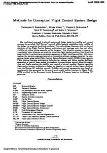
requirements given in the previous section for recent rotorcraft flight control development applications. Three different case studies are given; MQ-8B Fire Scout UAV, S-76D, and the ARH-70A. For these case studies, creative modeling solutions were found in order to meet the flight control requirements. This trio of case studies demonstrates the flexibility of the method and the variety of the ways in which it has been successfully used. Fire Scout The Fire Scout is being developed as a ship-based VTOL UAV for the U.S. NAVY. The MQ-8B, which is the current version of the Fire Scout, has an upgraded transmission, four rotor blades (as opposed to three on the earlier configuration, RQ-8A), and minor modifications to the airframe as compared to the RQ8A. The MQ-8B Fire Scout is depicted in Fig. 1.
Figure 1. MQ-8B first hover (reprinted from Ref. 7).
4
Frequency domain system identified models were exclusively used for the Fire Scout flight control design. A physics model was not available, so the identified linear models at various speed conditions across the envelope were “stitched” together with trim data and velocity based interpolation in order to provide for a continuous full-envelope simulation model. The Fire Scout program had many unique requirements that required careful consideration during model identification and flight control design/analysis. These challenges included: 1. To determine whether a 6 DOF model was sufficient for flight control design. 2. The need for reasonably accurate rotor rpm and torque modeling, since torque feedback was to be used in the control system. 3. A requirement to perform uncertainty analysis of the final flight control design. The following sections of the paper will provide highlights of the model identification, flight control design, and uncertainty analysis for the Fire Scout UAV. The hover flight condition will be shown throughout as an example. Hover Model Structure The first task in the modeling of the Fire Scout was determining the model structure. This required the engineers to discern whether a quasi-steady 6 DOF model would be sufficient to meet the fidelity requirements for flight control design at hover. For many rotorcraft, higher order rotor-states are needed in order to accurately model the aircraft over the frequency range of interest. In order to determine whether a quasisteady model was adequate, the intended bandwidth of the control system as well as the rotor characteristics were considered. The first consideration made in determining the validity of the use of a 6 DOF model was the frequency range of interest. According to flight control requirement #2, in the previous section of this paper: 1 ω c ≤ Freq Range of Interest ≤ 3ω c 3
(1)
The required cross-over frequency ω c for roll and pitch axis was planned to be around 3-4 rad/s. Therefore it was important to have a good model between approximately 1 rad/s to 12 rad/s. For a rotor system that is moderately stiff, such as the Fire Scout rotor, a quasi-steady (6 DOF) model was found to be valid up to 10-12 rad/s. A time delay was
also included to represent the effect of unmodeled rotor dynamics on the phase. This was possible because the rotor flapping and fuselage roll response modes are decoupled in a low or moderately stiff rotor. Engine and torque states were also included in the state-space structure to meet the requirement to obtain an accurate model of the torque. The final model structure was:
[
Mx& = Fx + Gu (t − τ )
(2)
y = H 0 x + H 1 x&
(3)
p q r φ θ
x= u v w
[
y = u& v& w& a x
[
ay
u = δ lon
az
δ lat
p q r ΩR
δ ped
]
(4)
]T
(5)
& T Ω Ω
ΩR
δ col
]T
T
T
(6)
Note that Ω = Ω R − r , where Ω R is the rotor response with respect to the fuselage ( Ω is defined in the opposite sign of fuselage yaw rate, r). A model of the torque response was needed to simulate the torque response and to design a torque feedback & T controller. Thus, the additional states Ω R Ω Ω were included for the engine and torque dynamics. A simple Taylor-series expansion was used to model the torque:
[
T& = Tt T + TΩ Ω + Tδ col δ col + Tδ ped δ ped
]
(7)
The rotor speed was modeled as a second order system with a washout: Ω
δ col
=
sK δ col
( s 2 + 2ζωs + ω 2 )( s + a)
(8)
Additionally, the rotor-rpm dynamics were coupled to the roll and yaw rate responses to collective in order to model the phase delay that is associated with the engine response. This was done by including LΩ and N Ω as effective control derivatives in the equations of motion instead of using Lδ col and N δ col .
Example Hover Results for Fire Scout Model The accuracy of the identified state-space models for Fire Scout was quantified by the identification cost functions, as well as visual overlays of time and frequency domain responses with flight data. The
5
responses were well predicted with the presented model structure over the frequency range of interest (1-12 rad/s) as indicated by the average cost function:
Magnitude(DB)
An average cost function below 100 is considered a very good model. As an example of the model accuracy, Fig. 2 shows the on-axis longitudinal responses for hover. The cost functions for these two individual responses were:
q/δ lon
0 -20 -40 -60 -80
Phase (Deg)
50 0 -50 -100 -150 -200 -250
J u& δ lon = 45.9
(11)
.
u/δ lon
20 -20
250 200 150 100 50 0 -50
0 -40 -60
1
Coherence
1
Coherence
(10)
The cost functions for these model fits were well within the desired values (