System level simulation of LTE networks. Josep Colom Ikuno, Martin Wrulich,
Markus Rupp. Institute of Communications and Radio-Frequency Engineering.
2010 IEEE 71st Vehicular Technology Conference: VTC2010-Spring
16–19 May 2010, Taipei, Taiwan
System level simulation of LTE networks Josep Colom Ikuno, Martin Wrulich, Markus Rupp Institute of Communications and Radio-Frequency Engineering Vienna University of Technology, Austria Gusshausstrasse 25/389, A-1040 Vienna, Austria Email: {jcolom, mwrulich, mrupp}@nt.tuwien.ac.at Web: http://www.nt.tuwien.ac.at/ltesimulator
Abstract—In order to evaluate the performance of new mobile network technologies, system level simulations are crucial. They aim at determining whether, and at which level predicted link level gains impact network performance. In this paper we present a M ATLAB computationally efficient LTE system level simulator. The simulator is offered for free under an academic, noncommercial use license, a first to the authors’ knowledge. The simulator is capable of evaluating the performance of the Downlink Shared Channel of LTE SISO and MIMO networks using Open Loop Spatial Multiplexing and Transmission Diversity transmit modes. The physical layer model is based on the postequalization SINR and provides the simulation pre-calculated ”fading parameters” representing each of the individual interference terms. This structure allows the fading parameters to be pregenerated offline, vastly reducing computational complexity at run-time.
I. I NTRODUCTION The Long Term Evolution (LTE) standard, specified by the 3rd Generation Partnership Project (3GPP) in Release 8, defines the next evolutionary step in 3G technology. LTE offers significant improvements over previous technologies such as Universal Mobile Telecommunications System (UMTS) and High-Speed Packet Access (HSPA) by introducing a novel physical layer and reforming the core network. The main reasons for these changes in the Radio Access Network (RAN) system design are the need to provide higher spectral efficiency, lower delay, and more multi-user flexibility than the currently deployed networks [2]. In the development and standardization of LTE, as well as the implementation process of equipment manufacturers, simulations are necessary to test and optimize algorithms and procedures. This has to be performed on both, the physical layer (link-level) and in the network (system-level) context. While link-level simulations allow for the investigation of issues such as Multiple-Input Multiple-Output (MIMO) gains, Adaptive Modulation and Coding (AMC) feedback, modeling of channel encoding and decoding [3] or physical layer modeling for system-level [4], system-level simulations focus more on network-related issues such as scheduling [5], mobility handling or interference management [6]. Along with the standardization process, commercially available LTE simulators have been developed. Equipment vendors, to this effect, have also implemented their own, proprietary solutions. Some universities and research centers have also developed such simulators, but to the authors’ knowledge none with publicly available source code.
The LTE system-level simulator [1] supplements an already freely-available LTE link-level simulator [7]. This combination allows for detailed simulation of both the physical layer procedures to analyze link-level related issues and system-level simulations where the physical layer is abstracted from link level results and network performance is investigated. The license under which the simulators are published allows for academic research and a closer cooperation between different universities and research facilities. In addition, developed algorithms can be shared under the same license again, facilitating the comparison and cross validation of algorithms and results and making them more credible. The LTE system-level simulator implementation offers a high degree of flexibility. For the implementation, extensive use of the Object-oriented programming (OOP) capabilities of M ATLAB, introduced with the 2008a Release have been made. Having a modular code with a clear structure based in objects results in a much more organized, understandable and maintainable simulator structure in which new functionalities and algorithms can be easily added and tested. This paper is organized as follows: in Section II we describe the overall structure of the LTE system-level simulator. In Section III we show how the physical layer has been abstracted in the link measurement model. Afterwards, we present the link performance model in Section IV, and Section V presents the main uses of the simulator as well as some conclusions. II. S IMULATOR OVERVIEW While link-level simulations are suitable for developing receiver structures [8], coding schemes or feedback strategies [9], it is not possible to reflect the effects of issues such as cell planning, scheduling, or interference using this type of simulations. Simulating the totality of the radio links between the User Equipments (UEs) and eNodeBs is an impractical way of performing system level simulations due to the vast amount of computational power that would be required [10]. Thus, in system-level simulations the physical layer is abstracted by simplified models that capture its essential characteristics with high accuracy and simultaneously low complexity. Figure 1 depicts a schematic block diagram of the LTE system-level simulator. Similarly to other system-level simulators, the core part consists of: (i) a link measurement model [11] and (ii) a link performance model [12].
shadow fading [dB]
macroscopic pathloss [dB]
network layout
1000 800
interference structure
macro-scale fading antenna gain shadow fading
link-measurement model
mobility management
micro-scale fading precoding
40
130
30
600
20
120
400 y pos (m)
base-station deployment antenna gain pattern tilt/azimuth
140
10
200
110
0
0 −200 −400
100
−10
90
−20
80
−30
−600
traffic model
−800 −1000
resource scheduling strategy power allocation strategy
link-performance model
throughput error rates
Fig. 1.
−1000
−500
0 x pos (m)
500
1000
70
−40 −1000
−500
0 x pos (m)
500
1000
link adaptation strategy
error distribution
Schematic block diagram of the LTE system level simulator
The link measurement model abstracts the measured link quality used for link adaptation and resource allocation. On the other hand the link performance model determines the link Block Error Ratio (BLER) at reduced complexity. As figures of merit, the simulator outputs traces containing throughput and error rates, from which their distributions can be computed. Implementation-wise, the simulator flow follows the pseudo-code below. The simulation is performed by defining a Region Of Interest (ROI) in which the eNodeBs and UEs are positioned and a simulation length in Transmission Time Intervals (TTIs). It is only in this area where UE movement and transmission of the Downlink Shared Channel (DLSCH) are simulated. for each simulated TTI do move UEs if UE outisde ROI then reallocate UE randomly in ROI for each eNodeB do receive UE feedback after a given feedback delay schedule users for each UE do 1- channel state → link quality model → SINR 2- SINR, MCS → link perf. model → BLER 3- send UE feedback Where, ”→” represents the data flow in and out of the simulator’s link abstraction model. In the M ATLAB implementation, the separated structure in the pseudo-code is maintained, allowing for easy adding of new functionalities and algorithms. III. L INK MEASUREMENT MODEL In order to abstract the measured link quality, and as shown in the pseudocode, the Signal to Interference and Noise Ratio
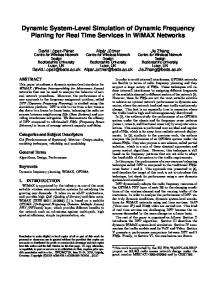
Fig. 2. Left: Macrosopic pathloss LM,b11 ,uj , 70 dB MCL, θ3dB = 65◦ /15 dBi antenna, 128.1 + 37.6 log10 (R [Km]) pathloss. Right: spacecorrelated shadow fading LS,b11 ,uj
(SINR) has been utilized as metric [13]. Specifically, a persubcarrier post-equalization symbol SINR. The link measurement model abstracts the measurements for link adaptation and resource allocation and aims at reducing run-time computational complexity by pregenerating as many of the needed parameters as possible. This shifts most of the computational burden to an off-line task that pregenerates and stores the results in trace files that can be (re-)used at simulation time. Special care has been taken as to account for the spatial and time correlation of the channel present in a wireless cellular system. To this effect, the link quality model has been split into three parts, which are afterwards combined to obtain post-equalitzation symbol SINR expressions: (i) macroscopic pathloss, (ii) shadow fading, and (iii) small-scale fading (SISO and MIMO). A. Macroscopic pathloss The macroscopic pathloss between an eNodeB sector and UE is used to jointly model both the propagation pathloss due to the distance and the antenna gain. It is noted as LM,bi ,uj , where bi denotes the i-th transmitter: 0 for the attached eNodeB (desired signal) and 1, . . . , Nint for the Nint interfering eNodeBs and uj the j-th UE, which then determines the (x, y) position. It is implemented as a pathloss map that can be computed once and, as long as the network layout is kept the same, be reused. The map specifies for each point in the simulated ROI the macroscopic pathloss between any point (x, y) and each transmitter. Figure 2 (left) depicts a generated macroscopic pathloss map using a θ3dB = 65◦ /15 dBi antenna [14] and and a distancedependent pathloss of 128.1 + 37.6 log10 (R [Km]) [15]. B. Shadow fading Shadow fading, LS,bi ,uj , is caused by obstacles in the propagation path between the UE and the eNodeB and can be interpreted as the irregularities of the geographical characteristics of the terrain introduced with respect to the average pathloss obtained from the macroscopic pathloss model. It is
typically approximated by a log-normal distribution of mean 0 dB and standard deviation 10 dB [14], [16]. While for simulating small scale fading a one-dimensional random function of time may suffice [17], as the waveform changes significantly even for small amounts of movement, this approach cannot adequately model the effects of shadow fading. As shadowing effects occur over a large area, in order to be able to capture the dynamics affecting macro-cell diversity in a realistic way a two-dimensional Gaussian process with appropriate spatial correlation is desirable [18]. For our modeling, a low-complexity method capable of introducing space correlation into the Gaussian process while still preserving its statistical properties as well as inter-site correlation has been used [19]. Figure 2 (right) depicts the resulting space-correlated shadow fading map for a given eNodeB. A UE traversing the ROI will experience a slowly changing pathloss (LS,b0 ,u0 ) due to shadow fading, LS,b0 ,u0 being correlated with LS,bi ,u0 , i = 1, . . . , Nint . Thus avoiding the unrealistic simulation scenario where spatially close UEs would have uncorrelated shadow fading losses. C. Channel modeling While the losses caused by the macroscopic pathloss and the shadow fading are position-dependent and time-invariant, small-scale fading is modeled as a time-dependent process. For each of the modeled MIMO transmission modes (Transmission Diversity (TxD) and Open Loop Spatial Multiplexing (OLSM)), a model based on a simple Zero Forcing (ZF) receiver has been developed. As of this version, systems with two transmit antennas have been modeled, but the derived SINR expressions can be easily extended for the LTE transmit modes using four antenna ports. Based on the derived models, a trace of fading parameters modeling the time-and-frequency variant behavior of the channel has been generated. These fading-parameters furthermore allow for a generation prior to the system level simulation itself, which reduces the run-time computational complexity significantly. The channel modeling aims at computing a per-layer SINR. In LTE, a spatial layer is the term used for the different streams generated by spatial multiplexing. A layer thus can be described as a mapping of symbols onto the transmit antenna ports. Each layer is then identified by a (precoding) vector of size equal to the number of transmit antenna ports [20]. 1) MIMO OLSM modeling: The LTE OLSM MIMO ¸ transmission mode consists of a precoding for Spatial Multiplexing (SM) with large-delay Cyclic Delay Diversity (CDD) [21]. In this mode, the precoding is defined by:
y(0) (i) x(0) (i) .. .. = W (i)D(i)U . . y(Nt −1) (i) x(ν−1) (i)
Where Nt specifies the number of transmit antennas and ν the number of layers, and D and U introduce the large-delay CDD. Noting F the W DU matrix product, H0 the channel for the received signal, H1−Nint the channel from the i-th interfering ˆ we eNodeB, from a total of Nint , and an estimated channel H have
ˆ 0 F )+ (H0 F )x0 + (H ˆ 0 F )+ n + x ˜ = (H
N int X
ˆ 0 F )+ (Hi F )xi , (H
i=1
where ’+’ denotes the pseudoinverse. Denoting A = ˆ )+ (HF ), B = (HF )+ and Ci = (H ˆ 0 F )+ (Hi F ), and (HF denoting the matrix elements as aij , A[i, j] we can express the SINRi for the symbols received in layer i as |aii |2 Pi
SINRi = X
|aij |2 Pj + σ 2
j6=i
ν X
|bik |2 +
k=1
N int X
ν X
|cl,im |2 Pl,m
l=1 m=1
(1) Where Pi is the power received at layer i after macro and shadow fading losses and σ 2 the receiver noise, assumed uncorrelated. Assuming a homogeneous power distribution Pl = Ptx /ν, we defined fading parameters: Pthe following 2 ζ = |aii |2 and ξ = |a | , which model channel j6=i ij estimation errors (A = I for perfect channel knowlν×ν Pν 2 edge), ψ = |b | , which models the ZF receiver k=1 ik Pν 2 noise enhancement, and θ = m=1 |cl,im | , modeling the interference. We can then express SINRi,u for UE u as SINRi,u =
ζi LM,0,u LS,0,u Pl N int X ξi Pl + ψi σ 2 + θi,l LM,l,u LS,l,u Pl,m
(2)
l=1
Where LM,bi ,u and LS,bi ,u represent the macro and shadow fading pathlosses between the UE u and its attached eNodeB (for bi = 0) and its interferers (bi = 1, . . . Nint ) respectively. 2) MIMO TxD modeling: For TxD, the precoding operation for the two TX antenna case uses the Alamouti scheme [21], [22], which can be written as � � � (0) � � � � � y0 h h(1) x n = · 0 + 0 y1∗ x1 n1 h(1)∗ −h(0)∗ | {z } | {z } | {z } | {z } y˜
˜ H
x ˜
n ˜
Where h(0) and h(1) contain the channel coefficients from the first and second transmit antennas to all NR receive antennas ˜ 0 channel and H ˜i Similarly to the OLSM case, for the H ˆ ˆ + ˜ ˜ ˜ (i = 1, ..., Nint ) interfering channels, A = H0 H0 , B = H0+ ˆ˜ )+ (H ˜ i ) have been defined. Then, similarly and Ci = (H 0 to Equation (1), we obtain
SNR−CQI measured mapping
LTE BLER, CQIs 1-15, SISO AWGN, 5000 subframes
CQI
−1
BLER
10
−2
10
−3
10 −10
−5
0
5 10 SNR [dB]
15
20
25
Fig. 3. BLER curves obtained from 1.4 MHz, single-user, 5000 subframes long, SISO AWGN simulations for all 15 CQI values. From CQI 1 (leftmost) to CQI 15 (righmost)
15 14 13 12 11 10 9 8 7 6 5 4 3 2 1 0 −20
SNR−CQI mapping model
CQI
0
10
−10
0 10 SNR [dB]
20
30
15 14 13 12 11 10 9 8 7 6 5 4 3 2 1 0 −20
Pl
X
|aij |2 + σ 2
j6=i
ν X
|bik |2 +
N int X
ν X
l=1 m=1
k=1
SINRi can then be expressed in an identical form as for the (2)) by having ζ = |aii |2 , P OLSM2 case (Equation Pν P ν 2 2 ˜ ik | and θl = ξ = j6=i |aij | , ψ = k=1 |h m=1 |cl,im | . 3) SISO modeling: As for the Single-Input Single-Output (SISO) case, the SINR for a given subcarrier can be written as SINR =
Ptx , Nint 1 2 X |hl |2 σ + Ptx,l |h0 |2 |h0 |2 l=1
thus only a trace of the noise and the interference parameters |hl |2 1 and is needed. |h0 |2 |h0 |2 IV. L INK PERFORMANCE MODEL The link performance model determines the BLER at the receiver given a certain resource allocation and Modulation and Coding Scheme (MCS). For LTE, 15 different MCSs are defined, driven by 15 Channel Quality Indicator (CQI) values. The defined CQIs use coding rates between 1/13 and 1 combined with 4-QAM, 16-QAM and 64-QAM modulations [23]. To asses the BLER of the received Transport Blocks (TBs), a set of Additive White Gaussian Noise (AWGN) link-level performance curves are employed. The SINR-to-BLER mapping then requires of an effective SINR value γeff , obtained from mapping the set of sub-carrier-SINRs assigned to the UE TB to an AWGN-equivalent SINR. Figure 3 shows the SISO AWGN ¸ BLER curves the link performance model utilizes [7]. The Exponential Effective Signal to Interference and Noise Ratio Mapping (EESM) [24], [25], [26] is the method currently used to obtain a TB effective SINR γeff which can be used
20
30
to map to the BLER obtained from AWGN link-level simulations. The effective SINR γeff is obtained by performing the following non-linear averaging of the several Resource Block (RB) SINRs:
γeff = EESM(γi , β) = −β · ln |cl,im |2 Pl,m
0 10 SNR [dB]
Fig. 4. CQI mapping. BLER=10% points from the BLER curves (left) and SINR-to-CQI mapping function (right)
|aii |2 Pl
SINRi =
−10
N 1 X − SINR i · e β N i=1
! .
Where N is the total number of sub-carriers to be averaged and β is calibrated by means of link level simulations to fit the compression function to the AWGN BLER results [13]. It is possible to consider not all of the TB sub-carriers but only a subset, as long as the frequency spacing between two SINR values does not exceed half of the coherence bandwidth [13]. Thus, in our channel traces, we reduced the amount of memory needed for a simulation by using only two sub-carrier SINRs per RB to obtain γeff . Using AWGN BLER curves, γeff is mapped to BLER. It is then decided via a coin toss whether the given received TB was received correctly and ACK reporting is subsequently generated. Related to the link performance model, the CQI feedback reporting provides the eNodeB with a figure of merit of the state of the channel of the UE. For the CQI feedback strategy, the SINR-to-CQI mapping is realized by taking the 10% points of the BLER curves, obtaining the mapping shown in Figure 4. The obtained CQIs are afterwarfds floored to obtain the integer CQI values that are reported back to the eNodeB. V. M AIN USES , SIMULATION RESULTS AND CONCLUSIONS In this paper we present a LTE system level simulator capable of simulating LTE SISO and MIMO networks using TxD or OLSM transmit modes and offered for free under an academic, non-commercial use license. The main purpose of this tool is to assess the network performance increase of new scheduling algorithms (Figure 5). Testing Fractional Frequency Reuse (FFR) strategies implemented at the scheduler level, as well as the network impact of different receiver types and channel quality feedback strategies, provided accurate modeling of those, can also be tested. SINR optimization (Figure 6) via electrical [27] and mechanical tilting and with pathloss maps imported from
UE and sector throughput, 20 UEs/sector, 5 MHz bandwidth 1 0.9 0.8 0.7
F(x)
0.6 0.5 0.4 0.3 OLSM, max C/I OLSM, round robin TxD, max C/I TxD, round robin
0.2 0.1 0 −100
0
100
200
300
400
500
600
UE throughput, 20 UEs/sector (kb/s)
5
0
10
15
20
25
Cell throughput (Mb/s)
Fig. 5. UE and cell throughput CDFs: TxD and OLSM, max C/I and round robin schedulers ROI max SINR (macroscopic fading) [dB]
ROI max SINR (macroscopic and shadow fading) [dB]
1000 8
800
13
18
8
13
15
18
600 3
y pos [m]
400
7
12
17
3
7
12
10
17
200 0
2
6
11
16
19
2
6
11
16
19
5
−200 −400
1
5
10
15
1
5
10
15
0
−600 −800 −1000
4
−1000
−500
9
0
14
500
4
1000
−1000
−500
9
14
0
500
−5 1000
x pos [m]
x pos [m]
Fig. 6. Sector SINR, calculated with distance dependent macroscale pathloss only (left) [15] and additional lognormal-distributed space-correlated shadow fading [19] (right)
network planning tools can also be easily added, thus enabling validation simulations against network planning tools, which usually use an even more abstract modeling of the physical layer The availability of its source code allows its results to be cross-checked and validated and researchers to compare algorithms in a standardized system. Together with the LTE link-level simulator [7], it forms, to the best of the authors’ knowledge, the only link-and-system LTE simulation suite openly available for research purposes. ACKNOWLEDGMENT The authors would like to thank the whole LTE research group for continuous support and lively discussions. This work has been funded by the Christian Doppler Laboratory for Wireless Technologies for Sustainable Mobility, as well as mobilkom austria AG, KATHREIN-Werke KG, and the Institute of Communications and Radio-frequency Engineering. The views expressed in this paper are those of the authors and do not necessarily reflect the views within the partners. R EFERENCES [1] [Online]. Available: http://www.nt.tuwien.ac.at/ltesimulator/ [2] E. Dahlman, S. Parkvall, J. Skold, and P. Beming, 3G Evolution: HSDPA and LTE for Mobile Broadband. Academic Press, Jul. 2007.
[3] J. Colom Ikuno, M. Wrulich, and M. Rupp, “Performance and modeling of LTE H-ARQ,” in Proc. ITG International Workshop on Smart Antennas (WSA), Berlin, Germany, Feb. 2009. [4] M. Wrulich and M. Rupp, “Computationally efficient MIMO HSDPA system-level evaluation,” EURASIP Journal on Wireless Communications and Networking, vol. Volume 2009, 2009. [5] C. Shuping, L. Huibinu, Z. Dong, and K. Asimakis, “Generalized scheduler providing multimedia services over HSDPA,” in Proc. IEEE International Conference on Multimedia and Expo, 2007, pp. 927–930. [6] M. Casta˜neda, M. Ivrlac, J. Nossek, I. Viering, and A. Klein, “On downlink intercell interference in a cellular system,” in Proc. IEEE 18th International Symposium on Personal, Indoor and Mobile Radio Communications (PIMRC), 2007, pp. 1–5. [7] C. Mehlf¨uhrer, M. Wrulich, J. C. Ikuno, D. Bosanska, and M. Rupp, “Simulating the long term evolution physical layer,” in Proc. of the 17th European Signal Processing Conference (EUSIPCO 2009), Glasgow, Scotland, Aug. 2009. ˇ [8] M. Simko, C. Mehlf¨uhrer, M. Wrulich, and M. Rupp, “Doubly Dispersive Channel Estimation with Scalable Complexity,” in Proc. ITG International Workshop on Smart Antennas (WSA), Bremen, Germany, Feb. 2010. [9] S. Schwarz, M. Wrulich, and M. Rupp, “Mutual information based calculation of the precoding matrix indicator for 3GPP UMTS/LTE,” in Proc. ITG International Workshop on Smart Antennas (WSA), Bremen, Germany, Feb. 2010. [10] M. Wrulich, W. Weiler, and M.Rupp, “HSDPA performance in a mixed traffic network,” in Proc. IEEE Vehicular Technology Conference (VTC) Spring 2008, May 2008, pp. 2056–2060. [11] M. Wrulich, S. Eder, I. Viering, and M. Rupp, “Efficient link-to-system level model for MIMO HSDPA,” in Proc. of the 4th IEEE Broadband Wireless Access Workshop, 2008. [12] K. Brueninghaus, D. Astely, T. Salzer, S. Visuri, A. Alexiou, S. Karger, and G.-A. Seraji, “Link performance models for system level simulations of broadband radio access systems,” Sept. 2005. [13] M. of WINNER, “Assessment of advanced beamforming and MIMO technologies,” WINNER, Tech. Rep. IST-2003-507581, 2005. [14] Technical Specification Group RAN, “E-UTRA; LTE RF system scenarios,” 3rd Generation Partnership Project (3GPP), Tech. Rep. TS 36.942, 2008-2009. [15] ——, “Physical layer aspects for E-UTRA,” 3rd Generation Partnership Project (3GPP), Tech. Rep. TS 25.814, 2006. [16] W. C. Lee, Mobile Communications Engineering. McGraw-Hill Professional, 1982. [17] W. C. Jakes and D. C. Cox, Microwave Mobile Communications. WileyIEEE Press, 1994. [18] X. Cai and G. Giannakis, “A two-dimensional channel simulation model for shadowing processes,” Vehicular Technology, IEEE Transactions on, Nov. 2003. [19] H. Claussen, “Efficient modelling of channel maps with correlated shadow fading in mobile radio systems,” Sept. 2005. [20] S. Sesia, I. Toufik, and M. Baker, LTE, The UMTS Long Term Evolution: From Theory to Practice. John Wiley & Sons, 2009. [21] Technical Specification Group RAN, “E-UTRA; physical channels and modulation,” 3rd Generation Partnership Project (3GPP), Tech. Rep. TS 36.211 Version 8.7.0, May 2009. [22] S. Alamouti, “A simple transmit diversity technique for wireless communications,” IEEE Journal on selected areas in communications, 1998. [23] Technical Specification Group RAN, “E-UTRA; physical layer procedures,” 3rd Generation Partnership Project (3GPP), Tech. Rep. TS 36.213, Mar. 2009. [24] E. Tuomaala and H. Wang, “Effective SINR approach of link to system mapping in OFDM/multi-carrier mobile network,” in Mobile Technology, Applications and Systems, 2005 2nd International Conference on, Nov. 2005. [25] X. He, K. Niu, Z. He, and J. Lin, “Link layer abstraction in MIMOOFDM system,” in Cross Layer Design, 2007. IWCLD ’07. International Workshop on, Sept. 2007. [26] R. Sandanalakshmi, T. Palanivelu, and K. Manivannan, “Effective SNR mapping for link error prediction in OFDM based systems,” in Information and Communication Technology in Electrical Sciences (ICTES 2007), 2007. ICTES. IET-UK International Conference on, Dec. 2007. [27] L. Thiele, T. Wirth, K. Brner, M. Olbrich, V. Jungnickel, J. Rumold, and S. Fritze, “Modeling of 3D Field Patterns of Downtilted Antennas and Their Impact on Cellular Systems,” in Proc. ITG International Workshop on Smart Antennas (WSA), Berlin, Germany, Feb. 2009.