the crash of a data source or server in MARS, were both found to ... growth of other services, the complexity of network protocol has ..... We assume a hard crash for our system. There is no recovery from this state, as when the home agent ...
Systematic Testing of Protocol Robustness: Case Studies on Mobile IP and MARS Shamim Begum, Meeta Sharma, Sandeep Gupta, Ahmed Helmy
Abstract
However, the asymptotic complexity was not a�ected.
Systematic Testing of Robustness by Evaluation of Synthesized Scenarios STRESS is a methodology developed for the systematic testing and veri cation of multipoint protocols. The algorithms developed in [1] are able to generate topologies and sequences of events that rigorously test the correctness or performance of the protocol. The STRESS methodology has been used to conduct studies on the correctness and performance of multipoint protocols like Protocol Independent Multicast (PIM). In this paper, we extend the STRESS method to Mobile IP protocol and the MARS protocol for supporting IP-multicast over ATM. For each protocol, we develop the protocol model and analyze its robustness and complexity of search algorithms provided by STRESS , namely the Fault-Oriented Test Generation and Fault-Independent Test Generation. In the process, we identify the limitations of the existing STRESS models and algorithms, and propose extensions to carry out our case studies. With the aid of stress, we were able to identify several protocol behaviors that either lead to error or performance degradation. For Mobile IP (MIP), we identi ed such behaviors with the crash of a home agent or the loss of a registration message. For MARS, undesired behavior was detected with the crash of MARS server or source and the selective loss of a join or leave message. The complexity of forward search, for our case studies, was found to be O(n2 ) for MARS. Incorporating the fault model in the search was found to a�ect the number of states searched. The crash of a home agent in MIP, and the crash of a data source or server in MARS, were both found to increase the number of states searched.
1 Introduction Protocol veri cation is the process of ensuring the logical consistency of the protocol speci cation, independent of any particular implementation. The typical properties addressed for protocol veri cation are safety, liveness and responsiveness. A protocol can be correct in isolation, but might be faulty when interacting with other layer protocols. With the exponential growth of Internet in recent years and with growth of other services, the complexity of network protocol has increased and along with it the protocol veri cation and testing has also become more di�cult. Systematic Testing of Robustness by Evaluation of Systematic Scenarios (STRESS) [1] provides a framework for the systematic design and testing of multicast protocols. The framework integrates test generation algorithms with simulation and implementation. STRESS uses a nite state machine (FSM) model of the protocol and uses a mix of forward and backward search techniques to generate the tests. The output tests include a set of protocol events and network failures that lead to violation of protocol correctness and behavioral requirements. In this paper, we extend the STRESS methodology and apply it to two case study protocols. The STRESS methodology is brie y described in Section 3. Our case studies belong to two di�erent domains, namely, IP mobility and multicast over ATM. The growth of wireless services along with the increase in portable computers, necessitates support for mobility in the Internet. The Mobile IP proto1
col (MIP) allows mobile hosts to send and receive packets addressed with their home address, regardless of the IP address of their point of attachment to the Internet [5, 15]. The main mechanism in MIP is the registration mechanism, through which the mobile node (MN) informs its home agent (HA) of its new location. Proper registration is essential for correct packet forwarding. If the registration mechanism is successful, then the home agent intercepts the packet for the mobile node and encapsulates and sends to the binding for that mobile node, at the other end the foreign agent (mobility agent) decapsulates the packet and sends to the mobile node. If the registration mechanism is not correct, then this may lead to serious errors. It is because of this reason we study robustness of MIP, especially the registration mechanism. Multicast Address Resolution Server (MARS) provides the mechanisms to support IP multicast services on ATM networks [11]. The MARS acts as a registry of multicast group membership, storing the IP/ATM addresses of ATM endpoints who consider themselves to be members of a given IP multicast group at any instant of time - the set of such endpoints are de ned as a Cluster. The server maintains a point-to-multipoint cluster control VC with all the cluster members on which it broadcasts group membership information. When a cluster member wants to join a group, it sends join request to the server that relays the join over cluster control Virtual Circuit (VC). An active source, upon reception of this relayed join message, adds the new receiver as a leaf node of the VC connected to the group. Since the relayed join message is multicast over cluster control VC, it might happen that the receiver which sent the join request received the relayed join while it gets lost from the server to the source - such a scenario leads to packet loss. We study the behavior of protocol under condition like selective loss of join and Leave messages using the STRESS techniques. The rest of the document is organized as follows. Section 2 presents the related work in Protocol Veri cation and STRESS. Section 3 gives a brief overview of the STRESS methodology, the framework and the formalization of the problem. Section 4 gives the details of the case study done on Mobile IP proto-
col. Section 5 gives the modeling and results for the MARS protocol. A brief discussion about the analysis and results is given in Section 6. Section 8 concludes by giving a brief summary of the work done and future research directions.
2 Related Work There has been signi cant research performed on veri cation of protocols, that address protocol safety and liveness properties. The two main approaches to this have been Theorem Proving and Reachability Analysis [9, 10]. In Theorem Proving, a set of axioms are de ned and relations are constructed based on these axioms to prove the desirable properties mathematically. In Reachability Analysis algorithms, all the possible states are generated and all states reachable from a given state are inspected. However, this method su�ers from the problem of state explosion. Protocols can be evaluated for correctness or performance. STRESS proposes a set of algorithms for generating test scenarios that target robustness and correctness violation, or worst case performance [1, 2]. STRESS has been applied to case studies on multicast routing protocols (PIM-DM and PIM-SM) and reliable multicast [4]. However, it has not been applied to wireless/mobile protocols or inter-operability protocols. We believe there are lessons to be learnt in these case studies. We investigate two protocols in those domains in our study. Earlier work [16] done for modeling MIP has been for veri cation of the protocol. To the best of our knowledge, there has been no work done with regards to testing of MIP for robustness. Not much work has been done for studying MARS protocol. Issues have been identi ed that a�ects the cluster size a MARS server can support [12]. Though we study the robustness of this protocol, this methodology can be extended to study its scalability also.
3 Overview of STRESS One of the main issue addressed by STRESS [1, 2, 3] is the development of test generation algorithms for 2
1. FSM Model: Every instance of the protocol is modeled by a deterministic FSM consisting of (i) a set of states (ii) a set of stimuli causing state transition, and (iii) a state transition function or table describing the state transition rules. For a system i, this is represented by the machine Mi = (S; �i ; �i ), where S is a nite set of state symbols, �i is the set of stimuli, and �i is the state transition function.
performance and correctness criterion. Test generation can be random or deterministic. There are two approaches the STRESS method uses for Automatic Test Generation, both of which are deterministic in nature: 1. Fault Oriented Test Generation (FOTG) A fault oriented test is generated for a speci c fault. It starts from the fault and synthesizes the necessary conditions to drive the protocol into error. This algorithm uses a mix of forward and backward searches [2]. 2. Fault Independent Test Generation (FITG) Fault Independent TG works without targeting individual faults as de ned by the fault model. Such an approach may employ a forward search technique to inspect the protocol state space after integrating the fault into the protocol model [3]. To use the STRESS methodology, we need to specify the system, i.e., protocol and message semantics in a processable form. The evaluation criterion, related to either performance or correctness, must be given as the input to the method in an appropriate form. The protocol design and description is then processed by the test generation algorithms, which use search techniques to synthesize the test scenarios based on evaluation criterion. The output of this process consists of tests which are sequences of protocol actions, topology characteristics and network failures, that meet the evaluation criteria. The formalism used to represent the protocol is a nite state machine (FSM). The interaction among the entities of the protocol is modeled by a global FSM (GFSM) [1]. The system consists of network and topology elements and a fault model. A test input pattern can be de ned as a 3-tuple [Topology, Events, Faults], where Events is a sequence of host events [1, 2, 3]. A fault is a low level anomalous behavior that may a�ect the protocol under test. Faults include loss of packets due to congestion, loss of state and delays. The fault model is integrated into the global FSM. In our case studies we use single selective message loss and machine crashes as fault models.
2. Global FSM Model: The global state is de ned as the composition of states of the individual entities of the system. The output messages from one entity may become input messages to other entities. Such interaction is captured by the GFSM model in the global transition table. The behavior of a system with n entities may be described by Mg = (Sg ; �g ; �g ), where Sg : S1 � S2 � : : : � Sn is the global state space, �g : [n i �i is the set of stimuli, and �g is the global state transition function Sg � �g ! Sg . We use a combination of the test generation methods to analyse the behavior of these two protocols in error condition and to study the complexity of the protocol state space. For each of the protocols, we identify the correctness criteria, states representing di�erent entities of the protocol, messages that a�ect these states and designed transition tables that describe the protocol mechanisms. For the message to be lost, we derive the minimum topology G required to trigger the message using FOTG algorithm [2]. We then apply forward search to G to study the recovery processes and backward searches to G to study its reachability. We also apply forward searches while increasing the network size and analyze the complexity of the protocol state space. Similarly, we apply backward searches while incorporating the faults. Mobility introduces the problem of dynamics and hando�. We also study more complex multicast protocols, like MARS, for the inter-operability using multicast, which makes the problem more complex. 3
maintains current location information for the mobile node. A Foreign Agent is a router on the mobile node's visited network which provides routing services to the mobile node while registered. The foreign agent de-tunnels and delivers to the mobile node. For datagrams sent by the registered mobile node the foreign agent may act as a default router. In general, home agents and foreign agents are termed as Mobility Agents. A Care-of-address is simply the endpoint of the tunnel, i.e., the tunnel terminates at the care-of-address of the mobile node. It should be an address to which the datagrams can be delivered via conventional IP routing. At the care-of-address the original datagram is removed from the tunnel and delivered to the mobile node.
CH
HA
CH: Correspondent Host MN
HA: Home Agent MN: Mobile Node
Figure 1: Basic Mobile IP
4.1 Protocol Mechanism
4 Case Study: Mobile IP
In this section a brief outline of the protocol along with the main mechanisms are provided. Mobility agents (home/foreign agents) advertise their presence by broadcasting agent advertisements. A mobile node may optionally solicit an agent advertisement message from any locally attached mobility agents through an agent solicitation message. A mobile node receives these agent advertisements and detects whether it is on home network or on foreign network. If the mobile node detects that is has moved from its home network it obtains a care-of-address on the foreign network. If the mobile node detects that it is still in its home network then it functions without any mobility services. If it detects that it is returning to its home network from being registered elsewhere, the mobile node deregisters with its home agent through exchange of a Registration Request and Registration Reply message with it. The mobile agent operating away from home then registers its care-of-address with the home agent through exchange of registration request and registration reply message with it. Datagrams sent to the mobile node's home address are intercepted by its home agent, tunneled by the home agent to the mobile node's care-of-address and then received at the tunnel end-point and delivered to the mobile-node. Datagrams sent by the mobile-node are delivered to
Mobile hosts are nodes that dynamically change their point of connectivity to the Internet. Mobile IP (MIP) de nes a mechanism which enables nodes to change their point of attachment without changing their IP address. MIP [5] protocols allow mobile hosts to send and receive packets addressed with their home network IP address, regardless of the IP address of their current point of connectivity. The challenge for supporting mobility at the IP layer is handling address changes. The mobility of the host is hidden through the use of home and foreign agents that handle the routing of packets to the mobile host. A mobile node discovers its connectivity to the network via the agent discovery mechanism. If it has moved, it tries to register with a foreign agent through registration mechanism [5, 6, 15]. Figure 1 shows the basic principle behind Mobile IP. The home agent intercepts the datagrams destined for the mobile node and encapsulates them and tunnels them towards the new care-of-address of the mobile node which is visiting some foreign network. According to the MIP speci cations we can de ne a Mobile Node as a host or a router that changes its point of attachment from one network to another network. A Home Agent is a router on a mobile node's home network which tunnels datagrams for delivery to the mobile node when it is away from home, and 4
their destination using standard routing mechanisms. The main mechanisms of the protocol have been described below:
HA
FA HA : Home Agent FA: Foreign Agent MN: Mobile Node
1. Agent Discovery It is the method by which the mobile node discovers whether it is still in its home network or has moved to some other network. When it has moved to another network then it determines a care-of-address being o�ered by the foreign network.
MN
Mobile node is in Home network
MN
Mobile node has moved to a foreign network
Figure 2: Topology considered for MIP study
4.2 Modeling the Protocol
2. Move Detection One method of move detection is based upon the Lifetime Field within the main body of the Advertisement portion of the Agent Advertisement. A mobile node records the Lifetime received in any Agent Advertisements, until that Lifetime expires. If the mobile node fails to receive another advertisement from the same agent within the speci ed Lifetime, it assumes that it has lost contact with the agent.
Figure 2 shows the topology considered. In our modeling we consider a LAN with a home agent and another LAN with a foreign agent1. As described in Section 3, a protocol is modeled as FSM and the interaction between the di�erent entities of the protocol are captured by the Global FSM. The modeling of the mobile node, Home Agent and Foreign Agent is performed according to the protocol mechanism described in section 4.1. A nite state machine consists of a set of states, set of stimuli which cause the state transitions and a state transition table which describes the state tran3. Registration sition rules. In our system we have considered a LAN Mobile IP provides a exible mechanism for mo- with one home agent, one or more foreign agents and bile nodes to communicate their current reacha- one Mobile node. bility information to their home agent. It is the method by which mobile nodes: 4.2.1 FSM Model For a speci c Mobile Node (MN)-Foreign Agent (FA) Pair, we de ne the states w.r.t a speci c LAN to which the Foreign Agent (FAj ) is connected. All possible system states are listed in Table 1. The various timers modeled are listed in Table 2. The possible states for mobile node, home agent, foreign agent are as follows: � For Mobile Node : InHAi ,InFAij ,Regmnij , DeRegmnij ,EMi � For Home Agent : NModei , Tij ,EHi
(a) Request forwarding services when visiting a foreign network (b) Inform their home agent of their current care-of-address (c) Deregister when it returns home
A mobile node initiates a registration whenever it detects a change in its network connectivity. Agent advertisements should not cause a mobile agent to attempt a new registration, if its current registration has not expired and it is still 1 We present the one FA model for simplicity and illustrareceiving Agent Advertisements from the agent tion, whereas our case study actually included multiple FAs, with which it is currently registered. and that will be shown in Section 6 in the paper 5
State Symbol Meaning InHAi DAi Regmnij DeRegmnij InFAij EMi NModei Tij EHi NMNi Regfaij DeRegfaij DTij
MNi in it's Home Network MNi discovering an Agent MNi tries to register its new care-of-address MNi deregisters the bindingj MNi registered with FAj MNi has lost it's state HA has no binding for MNi HAi encapsulates the packets to the FAj HAi has crashed. FAj has no binding for MNi FAj tries to register MNi with the home agent FAj deregisters the binding for MNi FAj decapsulates and sends the packet to the MNi
Table 1: Possible States of the MIP system
Timer
Description
RegLifetimeij Life Time of the registration RegReqij MNi /FAj send a Reg request again if the timer expires before getting a reply DeRegReqij MNi sends a DeReg request again if the timer expires before getting a reply Table 2: MIP Timer table
6
Stimulus
RegReqmn RegReqfa RegRepgrtha RegReprejha RegRepgrtfa RegReprejfa
Description
3. Crash: We consider crashes from which there is no recovery.
Request for registration sent from MN to FA Request for registration sent from FA to HA Registration granted by HA to FA Registration rejected by HA to FA Registration granted by FA to MN Registration rejected by FA to MN
4.2.4 Protocol Errors
Protocol errors can be de ned in terms of end-toend behavior as functional correctness requirements. Some of the protocol errors identi ed for MIP are: 1. Blackholes: When a mobile node moves into a new network region, there is an exchange of packets called a hando� and during this period, all normal transmissions are disrupted. This can lead to data loss, and sustained loss of data packets can lead to blackholes. 2. Duplication: Multiple copies of the same packet is received by the mobile node. 3. Registration Latency: There would be no packet delivery till the registration mechanism is successfully completed. 4. DeRegistration Latency: When a mobile node tries to deregister, there would still be packet forwarding to the foreign agent till the deregistration is granted. The foreign agent still remains a part of the forwarding tunnel until the deregistration has been granted.
Table 3: MIP Protocol Messages for Registration Mechanism
� For Foreign Agent : NMNj ,DTij ,Regfaij ,
DeRegfaij Table 3 lists the stimuli for the registration mechanism. Global FSM Model The global state is given in the order of home agent, mobile node, foreign agents. An Example global state for a case with two foreign agents, with mobile node registered with FAj , is given by Ti1 ,InFAij ,DTij ,NMNk .
4.2.2 Transition Table
The transition table describes for each stimulus, the condition of its occurrence. A condition is given as stimulus, and state or transition. At least one pre- 4.2.5 Correctness Criteria condition is required to trigger the stimulus. A post condition is a stimulus or transition which is triggered The correctness criteria identi ed for Mobile IP are: by the stimulus. Table 4 is the transition table for the 1. For each LAN, there must be exactly one home registration mechanism explained in Section 4.1. agent for a LAN. If there is no home agent, then there would be no packet forwarding to a mobile 4.2.3 Fault Models node in a foreign network. In our study we consider a single fault model i.e., only 2. If a move has been detected by a mobile node, one fault can happen at a time. The various fault then there must exist mobility agent to serve models incorporated in the study are as follows: that mobile node, else there absence of a mobility agent would lead to a black-hole problem. 1. Packet Loss: We consider the control message loss which can further lead to loss of packets 3. For every mobile node i and home agent j , if more than expected. j is i's home agent and i's current registration 2. Loss of State: The HA/MN/FA agent can loose is valid and has not expired, then the mobility the state information, like the information about binding of i in its home agent's binding table is the present binding of the mobile node. valid and has not expired. 7
Stimulus
Pre-condition
Post Condition ReqReqfa .(NMN! Regfa) RegRepgrtha .(NMode! T), RegReprejha RegRepgrtfa .(Regfa ! DT), RegReprejfa .(Regfa ! NMN) RegReqfa .(NMode! T) RegReprejfa .(Regfa ! NMN) RegRepgrtha .(Regfa ! DT) RegLife.(Regmn ! InFA) RegRepgrtha .(Regfa ! NMN) AgentSol.(Regmn ! DA) RegReprejha .(Regfa ! NMN)
RegReqmn AgentAdfa .(DA! Regmn ) RegReqfa RegReqmn .(NMN! Regfa) ReqRepgrtha RegReqfa .(NMode! T) ReqReprejha ReqRepgrtfa ReqReprejfa
Table 4: Transition table for MIP 2. Forward Implication : We then apply RegRepgrtfa to Gi in cases of losses and no losses. In this process we note the state of the GFSM considering no loss of RegRep from foreign agent to the mobile node. Gi+NoLoss and Gi+Loss represent the state of the GFSM for them respectively. Gi+NoLoss = Tij ,InFAij ,DTij Gi+Loss = Tij ,Regmnij ,DTij The mobile node would keep rejecting the packets it gets and there would be an additional loss of packets.This state would stay until the RegRequest timer expires and the mobile node again tries to register. Recovery Time= RegRequestRetx Timer + Time Taken in processing the registration message. Loss of register grant message leads to blackholes. There would be a degradation in the performance of the system, as all the packets are lost until there is a successful registration.
4. Consistency of registration: The mobility agent with which the mobile node i is believed to be registered (by the home agent) should actually be the one for which i is currently registered. If the mobile node has state FAij i.e., it MNi is in FAj , then the HA should be in Tij and FA should be in state DTij . States like (Tij ,InFAik ,DTij ) and (Tik ,InFAij ,DTij )... are incorrect states.
4.3 MIP Study Results
In this Section, we give a brief description of some of the error scenarios which can lead to some correctness violation or degradation in performance. For each study we describe the forward and backward implication. We have based our study on the protocol version in [5], and so our model presents a study of the basic protocol mechanisms and possible errors.
4.3.1 Loss of Register Grant message with one foreign agent 1. Topology Synthesis : We start with the mes-
4.3.2 Loss of Register Grant message with more than one foreign agent
sage RegRepgrtfa and the FOTG algorithm generates the topology necessary for the the message to be triggered. This is done iteratively considering all the preconditions and corresponding stimuli of preconditions. The topology synthesized is represented as Gi and is given by: Gi = Nmodei , Regmnij ,Regfaij . This represents the state of GFSM in which the RegRepgrtfa can be applied.
If there are more than one foreign agent on the LAN, the mobile node would get agent advertisements from multiple foreign agents. The MN attempts to register with one of them, say FAj . Here, we describe a simple case with two foreign agents(FAj ,FAk ) on the same LAN. We are assume that the mobile node is trying to register with FAj . 8
1. Topology Synthesis: Gi = Nmodei ,Regmnij , Regfaij ,NMNk 2. Forward Implication: Gi+NoLoss = Tij ,InFAij ,DTij ,NMNk The mobile node would keep rejecting the packets it gets and there would be an additional loss of packets. The mobile node would go into a discover agent state and would seek another agent. If the mobile node gets an advertisement from FAk , it would then try to register with that agent. Gi+Loss = Tij;ik ,InFAik ,DTij ,DTik , which is an incorrect state for there is inconsistency at the mobile node about its bindings. We assume that the home agent allows multiple bindings for the same mobile node.
an advertisement from the home agent. If the mobile node has moved to another foreign network, it would not be able to register with the foreign agent, as it does not have any information about it's home agent. This can be recovered from when it returns to its home network and it gets an advertisement from the home agent. The recovery in this case depends on where the mobile node is when it loses state. If the mobile node is in the home network, then it would recover as soon as it would receive a advertisement from its home agent. But if it is in a foreign network when it loses state, it would not be able to register, as it would not have any information about the home agent. It can only recover when it comes back into it's home network.
5 Case Study: MARS
4.3.3 Crash of a Home agent
In this section, we evaluate the utility of STRESS by applying it to Multicast Address Resolution Server (MARS) protocol. Multicasting over ATM network is achieved in two models - Virtual Circuit (VC) mesh based and Multicast Server (MCS) based. In both of the models, the MARS maintains the registry of multicast group membership by storing the IP/ATM addresses of ATM hosts and thus maintains the cluster. The rst model gives the most fundamental approach of multicasting where each source establishes its own point to multipoint VC with group members analogous to source based tree. In the MCS based model, all sources establish a point to point VC with an intermediate server called Multicast Server (MCS) that forwards the data to the group members analogous to shared tree [11]. For our case study, we take the mesh based approach.
If the home agent crashes then it might happen that the mobile node and foreign agent are respectively in the InFAij and DTij states and are expecting packets from the home agent, whereas there is no home agent. 1. Topology Synthesis: Gi = Ti ,InFAi ,DTi 2. Forward Implication: Gi+crash = EH,InFAi ,DTi , This is an incorrect state as there is no home agent for the system. This violates correctness criteria. We assume a hard crash for our system. There is no recovery from this state, as when the home agent crashes, the mobile node has no way of getting the packets destined for it, and it can never detect its point of connectivity properly2.
4.3.4 Loss of State for the Mobile Node
5.1 Protocol Mechanism
When the mobile node loses its state, it does not know the address of the home agent3 unless it gets In order to participate in multicast on ATM networks, 2 We can see that a design that allows only one home agent all ATM hosts need to register with the MARS server. without an election mechanism to elect an alternate one in case Once registered, the cluster members keep receiving of failure, is a poor system that is susceptible to single-point updates on group membership information that is of failure errors broadcast on the cluster control VC by the server. 3 It is also possible for a mobile node to use option 68 speci ed in [5] for DHCP to get a home address and a home agent address, but that is not a standard way
9
S
R
3. Sending to a group and Revalidation pro-
cess
M
When a host wants to send to a group, it sends a Request to the server for the address mapping of the group. The server replies back with list of IP and ATM addresses of the group members. The source then establishes a point-to-multipoint VC of which a receiver becomes a leaf node. Each source maintains a revalidation timer associated with that VC for the group. When expires, the timer turns a ag indicating the source to revalidate membership with the server. Consequently, when the active source gets packet to send, it starts revalidating the group membership information if the revalidation ag for the VC is set. The revalidation starts process by sending Request to the server. This process does not disrupt the source from sending packet to the group.
R
Figure 3: MARS VC-mesh based Model The functions of multicast data delivery can be described in terms of the following mechanism. 1. Registration/Deregistration When a host wants to be a member of the cluster, it sends a Registration message to the server including its ATM and IP address. Upon reception of this message, the server adds the host as a leaf node of the cluster control VC and sends its unique cluster member identi er. The server stores the address mapping for all of the registered cluster members. When a member wants to deregister, it sends Deregistration message to the server. Upon reception, the server drops it o� the cluster control VC.
5.2 Modeling the Protocol
2. Join/Leave When a cluster member wants to join group it sends Join message to the server and starts retransmission timer. Server relays the Join over cluster control VC. Upon reception of this relayed Join from server, the host which sent the join turns its timer o�. Upon reception of relayed Join, a source sending to the group adds the new receiver as a leaf node of the point-tomultipoint VC with the group members. In case of receiver leaving, the source drops the leaf o� the VC.
5.2.1 FSM Model
Figure 3 shows the VC-mesh based model we consider for our study where there is one MARS server serving the cluster. There are three entities in the protocols: server, source and receiver. As in multicast, sources need not be a members of the group to send to the group. A source can send to multiple groups, however, in our model we only consider source to send to only group and receivers to join that group. Our initial model only considers single source and we study the behavior under conditions where there can be multiple sources sending to the group. We de ne states of MARS server M, data source S and receiver R according to the protocol mechanisms. A subset of possible system states are listed in Table 5. The various timers modeled are listed in Table 6 - the values speci ed here are as recommended. The possible states for server, source and receivers are as follows:
10
� For MARS server: M, MRel , MRep � For Source: ES, CWS, CS, S, SUpdate , PS
State Symbol Meaning Mi MiRel ESi /ERi CWSi /CWRi CSi Si SiUpdate PSi CRi NRi Ri
Mi is serving as MARS Mi is relaying Join/Leave over cluster control VC Source/Receiver has no state information End point i joined cluster and willing to be Source/Receiver to the group Source i has no mapping for the group End point i has point-to-multipoint VC setup with the group Source is updating its point-to-multipoint VC with group Source i is sending to the group Receiver i has received Join relayed by server Receiver i has been added as leaf node to the point-to-multipoint VC rooted at source Receiver i is receiving multicast data from source Table 5: A subset of System States for MARS
Timer Description Retx Rev
Values
Join/Leave/Registration Retransmission interval 10 seconds Revalidation interval 10 seconds
Table 6: MARS Timer table
� For Receiver: ER, CWR, CR, NR, R Global FSM Model: GFSM represents the com-
it must receive a HJoin from the higher layer. The postconditions are the set of stimuli and transitions that this stimulus triggers - for example, a Join causes the state of server to change so that it triggers JRelay. Similarly, JRelay causes the source to trigger Update. In this model, Update represents all signaling functions available to local AAL user of the end points UNI interface, e.g., Establish unicast/multicast VC, add new leaf node to a previously established VC etc. In our model, the Update message is always deterministic which implies that a source always is able to add a new leaf node to the VC with the group to which it is sending or drop an existing leaf node from that VC.
bined states of all entities of the network. An Example global state representing a network with server, one source and two receivers is: Mi ,PSj ,Rk ,CWRl . In this network, i is the server, receiver k is receiving multicast data from source j and host l has joined 5.2.3 Fault Model cluster and willing to join the group. In this case study, we present GFSM in the order of server, source In our case study, we consider a single-fault model and receivers to present the topology or network. where only one fault can occur at a time. We de ne the following as the fault model:
5.2.2 Transition Table
Table 7 and Table 8 is a subset of the transition table and protocol messages for our model described in the previous section. The transition table describes the Join mechanism. The precondition of a stimulus is the condition required for the stimulus to be triggered - for example, for a host to trigger a Join, 11
1. Packet loss due to congestion, VC failure, insuf ciency of resources required for assembly and reassembly at AAL5. Therefore, packets are delivered correctly or dropped before arriving at the destination. 2. Loss of state, such as address translation infor-
Stimulus Pre Condition Join HJoin.(CWR!CWRTRetx ) JRelay Join.(M! MRel ) Update JRelay.(S! SUpdate )
Post Condition (M! MRel ).JRelay S! SUpdate .Update SUpdate ! S, CWRRetx ! CR
Table 7: Transition table for MARS: Join Mechanism
Stimulus Description
4. Blackholes: Consecutive packet loss between periods of packet delivery.
Rep
5. Registration latency: Lack of cluster membership information delivery after a host joins a cluster. 6. Deregistration latency: Unnecessary delivery of cluster membership information after a host leaves a cluster. 7. Revalidation latency: Lack of packet delivery when a source revalidates the group membership information, connects or disconnects a leafnode. This in turn leads to blackholes.
Req
Join JRelay Reg Update
request from sender/client to MARS for group membership MARS Reply to the sender/client with group membership mapping Join request from a client to MARS Join message when relayed by MARS over cluster control VC Registration request from a non member node to MARS Establish unicast/multicast VC add/drop a node from VC etc
Table 8: MARS Protocol Messages for Join mechanism
5.2.5 Correctness Criteria
mation and cluster membership information due Based on the fault model, we de ne the correctness to insu�cient memory, momentary crashes etc. criteria that we assume to be provided by the protocol designer. Once these conditions are satis ed, the state machine is assumed to be working correctly. 5.2.4 Protocol Errors And violating these conditions in stable state leads the state machine into error. For MARS and other multicast protocols, an error can happen in one of the following ways: 1. A host must be a registered cluster member to send to a group and to receive from a group. 1. Join latency: The time required by a receiver Violation of this condition may lead to packet joining the group to start receiving packet sent loss, i.e., registration latency, registration and to the group. join latency or blackholes. For example, GFSM state like (Mi ,CWSj ,Rk ) is not correct. 2. Leave latency: The time required by a receiver leaving the group to stop getting packets sent to 2. When a host joins a group with an active source, it must be added as a leaf node of the point the group. It leads to unnecessary packet recepto multipoint VC rooted at that source for the tion after a receiver leaves the group. group - i.e. the source must update its VC upon 3. Packet duplication: Multiple copies of a packet its join. Violation of this condition leads to is received by a receiver. revalidation latency. The revalidation latency 12
Message Next state of GFSM
is de ned as the time required for a source to request group membership information, receiving replies from server and add a new leaf node. For example, GFSM states like (Mi , CSj , CRk ), (Mi ,Sj ,Rk ,CRl ) are incorrect.
SPktj Reqj Repi Updatej
Mi , CSj , CRk MiRep , CSj , CRk Mi ,SjUpdate , CRk Mi , Sj , NRk
3. When a source receives group membership infor- Table 9: Recovery from error: Loss of JRelay for the mation from the server for a group with nonzero 1st receiver members in that cluster, the source must have point to multipoint VC rooted at itself. Violation of this condition leads to blackholes. 1. Topology synthesis: We start with the message JRelay and the method generates the topology 4. When a source sets up point to multipoint VCs necessary for it to be triggered - this is done for a group, the number of leaf nodes of the VC by iteratively considering all the preconditions must be equal to the number of group members and corresponding stimuli of preconditions. The in the cluster. Violation of this may lead to join topology thus synthesized is represented as Gi latency or black holes. States like (Mi , Sj , ERk ) and given by: is incorrect. Gi = MiRel , CSj , CWRkRetx . This represents 5. When a receiver is receiving packet, there must the state of GFSM in which JRelay can be apbe a source that has point-to-multipoint VC plied. through which the receiver is receiving the packet. Violation of this may lead to registra- 2. Forward implication and Recovery: We then aption and revalidation latency. States like (Mi , ply JRelay to Gi . In this process we note the ESj , Rk ) is incorrect. state of GFSM considering selective loss of JRelay from server to the source. Gi+NoLoss and Gi+Loss represent the state of GFSM considering 5.3 MARS Study Results no loss of JRelay and selective loss respectively and from our study, We apply FOTG to study the robustness of the protocol in the presence of message loss and loss of state. Gi+NoLoss = Mi , SjUpdate , CRk We present the scenario that violates the correctGi+Loss = Mi , CSj , CRk , this is a stable state ness condition and hence leads to an error state. For that violates correctness criteria 2 - receiver k aseach of the study, we describe the steps for topology sumes to join the group, but source is not adding synthesis, forward implication and backward implicaany VC. Since there is no VC for the group, the tion. revalidation process does not occur at this state, however, whenever the source gets a packet to send, it sends request to server and gets the ad5.3.1 Selective loss of JRelay dress mapping of the newly joined receiver. In JRelay is multicast by the server over cluster control this case, there was no VC setup for the group, VC. Here we consider the loss of the message from in fact, this loss of join message does not lead to server to the source. We study this scenario for two any packet loss. The recovery time of the state cases: for loss of JRelay i) when the rst receiver joins machine is de ned by the time to process Reand ii) when the nth receiver joins , because the state quest, Reply and Update messages as given in machine recovers from the error in di�erent ways in Table 9. these two cases.
Join of the rst receiver
Join of the nth receiver
13
Message Next state of GFSM Revj SPktj Reqj Repi Updatej
receivers in the network. This shows that the receiver which has already sent Leave message to the server, continues to receive packet from the source for the Recovery time period de ned in the previous subsection. This leads to unintended packet reception during leave.
Mi , SjRev , Rl , CRk Mi , PSj , Rl , CRk MiRep , PSj , Rl , CRk Mi ,SjUpdate , Rl , CRk Mi , SjUpdate , Rl , NRk
Table 10: Recovery from error: Loss of JRelay from 5.3.3 Crash of a source 2nd Receiver When a source crashes it momentarily loses its state and is triggered to empty state. This kind of crash can occur at any time and hence, we synthesize the 1. Topology synthesis for n = 2: topology required for all consecutive messages that Gi = MiRel , Sj , Rl , CWRkRetx may lead a cluster member to a source. Then we apply forward implication to study the behavior of 2. Forward implication and Recovery: systems states after crashes. First, we apply SCrash Gi+NoLoss = Mi , SjUpdate , Rl , CRk and arrive at the state of the system as (M, ES, R). Gi+Loss = Mi , Sj , Rl , CRk , this is a stable state This is an error state that violates condition no 5. that violates correctness criteria 2. The state The behavior of the system after application of host machine comes out of this error because of reval- stimuli are as follow: idation process. When the revalidation timer expires, it changes the state and when the source 1. SPkt after SCrash: Since the source loses its state, this leads to registration and revalidation gets next packet to send, it starts the revalidalatency before it recovers from the error state. tion process by initiating a Request to the server The recovery time is de ned as: Revalidation - however, it does not stop the source to send Time + Registration latency + Time to process data packet over the VC for the group, so it leads Request, Reply and setting up VC with the reto packet loss for a period of time de ned as folceivers. During this period, no receiver will relows. ceive any packet from the source. Recovery Time (Revalidation Latency) = Revalidation Timer interval + Time to process Request, 2. HLeave after SCrash: We apply this stimulus to to the state (M, ES, R). In this state, when the Reply and Update messages (Table 10). receiver sends Leave to server and the server mulBackward implication: Using backward implication ticast RRelay, the source does not have enough state to respond to this message. In this case, the the algorithm generates the sequence of messages sufsystem did not recover and it has to wait until cient to trigger JRelay message. The messages are SPkt, RegRep, HReg for the source and HJoin, HReg the source gets a packet to send to the group and starts registration and revalidation. for the receiver.
5.3.2 Selective loss of LRelay
We apply FOTG for this message - for brevity we only present the results we have got from this study. Like JRelay, LRelay is broadcast over the cluster control VC. The state machine comes out of the error state because the revalidation timer expires and same sequence of events occur independent of the number of
5.3.4 Crash of a receiver
The same steps are followed in this case. For simplicity we only present our ndings of forward implication after crash. When the leaf node of the source corresponding to the receiver drops, the source starts revalidating the group as soon as it gets packet to send. However, the server also disconnects the leaf
14
node associated with the receiver. Thus, the source does not add the receiver as it leaf node. This leads to blackhole in the receiver in case of SPkt after receiver's crash. If HJoin is applied after the crash, the receiver triggers registration and join that leads to the registration and join latency and eventually recover from the error.
1000 Forward Calls(with crash) Forward Calls(without crash) 900
800
Forward Calls
700
600
500
400
1. System with only one receiver: One possible minimum topology for a network with only one receiver (that crashes) is (M, S, ER) - this is an error state that violates condition 4. The system recovery process depends on the sequence of events that might happen after the crash. If the source sends packet before the revalidation timer expires, the receiver still gets packet from the VC - there is, in fact, no loss due to crash of the receiver. If the revalidation timer expires before the source has got packet to send, the source starts revalidation process during which the source keeps on sending packet over the cluster control VC and the receiver in turn does not lose any packet. 2. System with more than one receiver: In this case, one possible minimum topology is (M, S, ER, R) that satis es all correctness criteria. The system is not in error. However, when the receiver comes up it leads to registration and join latency.
5.3.5 Crash of the server If the server crashes and there is no election mechanism, the on-going activities of the group remains una�ected - for example, the source keeps sending to the group. However, when the revalidation timer expires or when a new host wants to join cluster or group, they send group address request or registration/join request to server which does not have any state information about the group or the cluster - this leads to an error from which there is no recovery. If there is multiple servers in the network, the scenario would be di�erent because of the server election mechanism and interaction between the servers.
300
200
100 1
2
3 4 5 6 7 Number of Foreign Agents
8
Figure 4: MIP: Number of Forward Calls vs Number of Foreign Agents
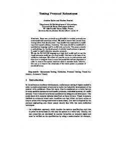
6 Complexity Analysis of the Search Algorithms We applied FITG to study the complexity of the state space. The search results shows the behavior of the algorithm with and without including faults. We identi ed the initial states for the network and applied forward search to it. We present the results for both of the case studies in this section. The number of expanded states represents the number of visited stable states. The number of forwards represents the number of times the state machine was advanced forward denoting the number of transitions between stable states. The number of error states represents the number of expanded states that violates the correctness condition. We study MIP for the complexity of FITG algorithm by varying the number of foreign agents. Only one home agent and one Mobile node were considered. Figures 4, 5 shows the comparison for the complexity with respect to the number of forward calls and the number of errors. The model was analyzed for complexity for cases with and without crash of home agent. The crash was a hard crash (from which there is no recovery). Crash of the home agent leads the system into an unrecoverable error state. The mobile node cannot receive any packets if it is not in the home network. Due to the error being an unrecover-
15
250000
80
Forward Calls
Errors(with crash) Errors(without crash) 70 200000
Forward Calls
60
Errors
50
40
150000
100000
30 50000 20
0
10 1
2
3 4 5 6 Number of Foreign Agents
7
0
8
2
4
6
8
10 12 14 16 18 20
Number of Receivers
Figure 5: MIP: Erros vs Number of Foreign Agents Figure 7: MARS: Number of Forward Calls vs Number of Receivers
16000
70000 Expand calls with source crash Expand calls without crash
Errors with source crash Errors without crash
60000
12000 50000 Number of Errors
Number of Expand calls
14000
10000 8000 6000
40000 30000
4000
20000
2000
10000
0 1
2
3
4 5 6 7 Number of Receivers
8
9
0
10
1
2
3
4 5 6 7 Number of Receivers
8
9
10
Figure 6: MARS: Number of Expand calls with Figure 8: MARS: Number of Error vs Number of crashes vs Number of Receivers Receivers
16
the number and states of the receivers, it might be in error or in correct state - for example, if at least one receiver is in receiving state, it becomes an error state, while on the other hand, if all receivers are in states prior to joining the group, it becomes a correct state. In case of an error, the source starts registration and comes out of the error state eventually. The complexity of FOTG algorithm increases non-linearly with the increase of number of receivers as given in gure 9.
1000 Rewind calls Backtracks Backward call
Number of Rewind/Backtrk/Bkwds
900 800 700 600 500 400 300 200 100 0 1
2
3 4 Number of Receivers
5
6
Figure 9: MARS: Number Rewind/Backtrack/Backwards vs Number Receivers
of of
able, the complexity of the search increases and there is also an increase in the errors. We study the complexity of FITG algorithm for MARS protocol by varying the number of receivers as shown in Figures 6, 7, 8, 9. The number of expand and forward calls increases non-linearly with number of receivers. The number of calls are O(n2 ) where n is the number of receivers in the network. The number of error states also increases non-linearly with number of receivers. We study the algorithms by varying number of sources and our study shows that the complexity remains same irrespective of that number. The reason is that a source only needs to register to the server as cluster member to send to the group. Once it is added as a cluster member, it does not add any complexity as long as there is no change in the group. We also study the complexity of search and errors with the crash of the source. We found that both the complexity and error increases when the source crashes though not signi cantly. The reason is that the crash is a soft crash, not a hard crash4 the source eventually recovers from the error and the recovery process leads to Registration latency. When the source crashes, it goes to an empty state that is also its initial state. In this state, depending on 4 In case of server crash, which is a hard crash, there is an abrupt increase in complexity of search algorithms
7 Summary We analyzed both the protocols to study their correctness and robustness. Using STRESS we were able to detect protocol errors and the exact sequence of events and de ne the time that is required for it to recover from the errors. Earlier work [16] done for modeling MIP has been for testing the speci cation, but it did not consider the loss and crash scenarios. In this case study we have studied the behavior for loss of control messages and also crash of home agent. Our study of MIP was based on [5], and did not include any route optimizations. A non-deterministic behavior in the register mechanism was observed. In our model, we have not modeled the method of rejecting or granting the registration request, i.e., the di�erent issues the mobility agent would consider before accepting or rejecting the request. In the case study of MARS, we have studied the behavior for selective loss of control messages and crashes of source, receiver and server. The model considered the deterministic behavior of protocol messages like Registration and Update, since we did not include lower layer mechanisms to verify the condition whether a new leaf node can be added to the point-to-multipoint VC rooted at server or source. Our results show that in general, the complexity increases in the order of n2 where n is the number of receiver and remains same with the increase of number of sources. However, crashing of source increases the complexity and errors slightly because of the error due to crash being recoverable.
17
8 Future Work
References
Both of the case studies are based on the speci cations [5, 11], which only describes the basic mechanisms. The modeling done for MIP does not include the authentication mechanisms. We need to add mechanisms which decide whether a registration has to be granted or rejected. Because of the absence of these mechanisms, the model in a way is a non-deterministic model. Enhancement to the basic mobile IP, like route optimization, caching at the foreign agents, have not been considered in the present model. Though including these mechanisms would increase the state space, it would capture the interactions with the correspondent hosts and also between the foreign agents. The STRESS methodology does not include the support for periodic timers. The method has also to be extended to incorporate the notion of real-time.
[1] A. Helmy and D. Estrin, \Simulation based 'STRESS' Testing Case Study: A Multicast Routing Protocol", Sixth International Symposium on Modeling, Analysis and Simulation of Computer And Telecommunication Systems (MASCOTS'98), July 1998. [2] A. Helmy, D. Estrin, S. Gupta, \Fault Oriented Test Generation for Multicast Routing Protocol Design", Formal Description Techniques and Protocol Speci cation, Testing and Veri cation (PSTV XVIII), 1998 IFIP TC6/WG6.1 Joint International Conference, Paris, France, November 1998. [3] A. Helmy, D. Estrin, S. Gupta, \STRESS Testing using Reduced Reachability Analysis: A Case Study for a Multicast Routing Protocol". [4] A. Helmy, D. Estrin, S. Gupta, \Systematic Testing of Multicast Routing Protocols: Analysis of Forward and Backward Search Techniques", to be published
In MARS model, adding a leaf node to a pointto-multipoint VC was deterministic. In order to be [5] C. Perkins, \IP Mobility Support", RFC 2002, non-deterministic, we need to extend the model to October 1996. incorporate the lower layer mechanisms. For example, we need to add features in our model so that [6] C. Perkins,\Mobile Networking Through Mobile IP", computer.org/internet/v2n1/perkins.htm any source has the ability to decide whether a new leaf node can be added or not based on lower layer mechanisms. Also, we did not study the protocol be- [7] C. Perkins, \Route Optimization in Mobile IP", Mobile IP Working Group, INhavior when there are multiple servers in the network TERNET DRAFT, Feb'99. draft-ietf-mobileipbecause it was based on [11] which does not give optim-08.txt information about interaction between current and backup servers. We need to specify their interaction Crocker, \ATM Signaling Support for IP over and study its behavior for a network with multiple [8] D. ATM", Network Working Group RFC 1755 servers and under condition of server crash. MARS protocol has been studied and issues have been iden- [9] E. Clarke and J. Wing \Formal Methods: State ti ed that a�ects the cluster size - the scalability can of Art and Future Directions", ACM Workshop be studied by incorporating the lower layer mechaon Strategic Directions in Computing Research, nisms to allow the server to decide whether it can Vol. 28, No. 4, pages 626-643, December 1996 add new leaf node to its cluster control VC depending on certain conditions. This requires extension of [10] F. Lin, P.Chu, and M. Liu, \Protocol Veri the current model and also, the current method used cation using Reachability Analysis", Computer in STRESS. Communication Review, Vol 17, No. 5, 1987. 18
[11] G. Armitage Bellcore,\Support for Multicast over UNI 3.0/3.1 based ATM Networks", Network Working Group RFC 2022, November 1996. [12] G. Armitage,\Issues a�ecting MARS Cluster Size", Network Working Group RFC 2121,, March 1997 [13] M. Abramovici, M.A Breuer, A.D. Friedman, \Digital Systems Testing and Testable Design", 1990, Computer Science Press. [14] R. Cole, D. Shur, C. Villamizar,\IP over ATM: A Framework Document", Network Working Group RFC 1932, [15] S.Cheshire, M.Baker, \Internet Mobility 4x4", SIGCOMM-96, August 1996, http: gunpowder.stanford.edu/publications/InternetMobility4x4,html [16] Zhe Dang and Richard A. Kemmerer\Using the ASTRAL model checker to analyze mobile IP";Proceedings of the 1999 international conference on Software engineering , 1999, Pages 132 142
19