Systems Biology Graphical Notation: Entity Relationship language Level 1
Nature Precedings : doi:10.1038/npre.2009.3719.1 : Posted 4 Sep 2009
September 3, 2009
Editors:
Nicolas Le Nov`ere Stuart Moodie Anatoly Sorokin Falk Schreiber Huaiyu Mi
EMBL European Bioinformatics Institute, UK CSBE, University of Edinburgh, UK University of Edinburgh, UK IPK Gatersleben & University of Halle, DE SRI International, USA
To discuss any aspect of SBGN, please send your messages to the mailing list
[email protected]. To get subscribed to the mailing list or to contact us directly, please write to
[email protected]. Bug reports and specific comments about the specification should be entered in the issue tracker https://sourceforge.net/tracker/admin/?atid= 1170625&group_id=178553.
Contents
Nature Precedings : doi:10.1038/npre.2009.3719.1 : Posted 4 Sep 2009
1 Introduction 1.1 SBGN levels and versions . . . . 1.2 Developments, discussions, and tions of updates . . . . . . . . . 1.3 Note on typographical convention
. . . . . notifica. . . . . . . . . .
1 1
3.3.1 Interactor Nodes connectivity definition . . . . . . . . . . . . . . . . 3.3.2 Syntactic rules . . . . . . . . . . . 3.4 Semantic description of Entity Relationships 3.4.1 Statements . . . . . . . . . . . . 3.4.2 Influences . . . . . . . . . . . . . 3.4.3 Logical Operators . . . . . . . . . 3.4.4 Cis and trans relationships . . . . 3.4.5 (In)Validation of ER maps . . . . .
1 2
2 Entity Relationship glyphs 2.1 Overview . . . . . . . . . . . . . . . . . 2.2 Controlled vocabularies used in SBGN Entity Relationship Level 1 . . . . . . . . . . 2.2.1 Entity material types . . . . . . . . 2.2.2 Entity conceptual types . . . . . . 2.2.3 Macromolecule covalent modifications 2.2.4 Miscellaneous terms . . . . . . . . 2.3 Entity nodes . . . . . . . . . . . . . . . . 2.3.1 Interactors . . . . . . . . . . . . . 2.3.2 Logical operators . . . . . . . . . 2.3.3 Glyph: Perturbing agent . . . . . . 2.3.4 Auxiliary units . . . . . . . . . . . 2.3.5 Glyph: Unit of information . . . . . 2.3.6 Glyph: State variable . . . . . . . 2.4 Relationships . . . . . . . . . . . . . . . 2.4.1 Statements . . . . . . . . . . . . 2.4.2 Glyph: Phenotype . . . . . . . . . 2.4.3 Influences . . . . . . . . . . . . . 2.5 Glyph: Annotation . . . . . . . . . . . . .
3 3 4 4 4 5 5 6 6 8 11 12 12 13 15 15 17 18 23
3 Grammar of Entity Relationships 3.1 Overview . . . . . . . . . . . . . . . . . 3.2 Concepts . . . . . . . . . . . . . . . . . 3.3 Syntax . . . . . . . . . . . . . . . . . .
25 25 25 25
26 26 27 27 27 27 28 28
4 Layout Guidelines for an Entity Relationship map 4.1 Introduction . . . . . . . . . . . . . . . . 4.2 Layout guidelines . . . . . . . . . . . . . 4.2.1 Requirements . . . . . . . . . . . 4.2.2 Recommendations . . . . . . . . . 4.2.3 Additional suggestions . . . . . . .
29 29 30 30 32 32
5 Acknowledgments 5.1 Main contributors . . . . . . . . . . . . . 5.2 Comprehensive list of contributors . . . . 5.3 Financial support . . . . . . . . . . . . .
34 34 34 34
A Complete examples of SBGN Entity Relationship Level 1 maps 36
ii
B Reference card
38
C Issues postponed to future levels C.1 Domains, sites and motives . . . . . . . . C.2 Generics and instances . . . . . . . . . .
40 40 40
Chapter 1
Nature Precedings : doi:10.1038/npre.2009.3719.1 : Posted 4 Sep 2009
Introduction The goal of the Systems Biology Graphical Notation (SBGN) is to standardize the graphical/visual representation of essential biochemical and cellular processes. SBGN defines comprehensive sets of symbols with precise semantics, together with detailed syntactic rules defining their use. It also describes the manner in which such graphical information should be interpreted. For a general description of SBGN, one can read: Nicolas Le Nov`ere, Michael Hucka, Huaiyu Mi, Stuart Moodie, Falk Schreiber, Anatoly Sorokin, Emek Demir, Katja Wegner, Mirit I Aladjem, Sarala M Wimalaratne, Frank T Bergman, Ralph Gauges, Peter Ghazal, Hideya Kawaji, Lu Li, Yukiko Matsuoka, Alice Vill´eger, Sarah E Boyd, Laurence Calzone, Melanie Courtot, Ugur Dogrusoz, Tom C Freeman, Akira Funahashi, Samik Ghosh, Akiya Jouraku, Sohyoung Kim, Fedor Kolpakov, Augustin Luna, Sven Sahle, Esther Schmidt, Steven Watterson, Guanming Wu, Igor Goryanin, Douglas B Kell, Chris Sander, Herbert Sauro, Jacky L Snoep, Kurt Kohn, Hiroaki Kitano. The Systems Biology Graphical Notation. Nature Biotechnology 27, 735 - 741 (2009). http://dx.doi.org/10. 1038/nbt.1558 This document defines the Entity Relationship visual language of SBGN. Entity Relationships are one of three views of a biological process offered by SBGN. It is the product of many hours of discussion and development by many individuals and groups.
1.1
SBGN levels and versions It was clear at the outset of SBGN development that it would be impossible to design a perfect and complete notation right from the beginning. Apart from the prescience this would require (which, sadly, none of the authors possess), it also would likely require a vast language that most newcomers would shun as being too complex. Thus, the SBGN community followed an idea used in the development of other standards, i.e. stratify language development into levels. A level of one of the SBGN languages represents a set of features deemed to fit together cohesively, constituting a usable set of functionality that the user community agrees is sufficient for a reasonable set of tasks and goals. Within levels, versions represent small evolution of a language, that may involve new glyphs, refined semantics, but no fundamental change of the way maps are to be generated and interpreted. Capabilities and features that cannot be agreed upon and are judged insufficiently critical to require inclusion in a given level, are postponed to a higher level or version. In this way, the development of SBGN languages is envisioned to proceed in stages, with each higher levels adding richness compared to the levels below it.
1.2
Developments, discussions, and notifications of updates The SBGN website (http://sbgn.org/) is a portal for all things related to SBGN. It provides a web forum interface to the SBGN discussion list (
[email protected]) and information 1
CHAPTER 1. INTRODUCTION
2
about how anyone may subscribe to it. The easiest and best way to get involved in SBGN discussions is to join the mailing list and participate. Face-to-face meetings of the SBGN community are announced on the website as well as the mailing list. Although no set schedule currently exists for workshops and other meetings, we envision holding at least one public workshop per year. As with other similar efforts, the workshops are likely to be held as satellite workshops of larger conferences, enabling attendees to use their international travel time and money more efficiently. Notifications of updates to the SBGN specification are also broadcast on the mailing list and announced on the SBGN website.
Nature Precedings : doi:10.1038/npre.2009.3719.1 : Posted 4 Sep 2009
1.3
Note on typographical convention The concept represented by a glyph is written using a normal font, while a glyph means the SBGN visual representation of the concept. For instance “a biological entity is encoded by the SBGN ER entity”.
Chapter 2
Nature Precedings : doi:10.1038/npre.2009.3719.1 : Posted 4 Sep 2009
Entity Relationship glyphs This chapter provides a catalog of the graphical symbols available for representing entities in Entity Relationship maps. There are different classes of glyphs corresponding to different classes of entity nodes, statements and influences. In Chapter 3 beginning on page 25, we describe the rules for combining these glyphs into legal SBGN Entity Relationships, and in Chapter 4 beginning on page 29, we describe requirements and guidelines for the way that maps are visually organized.
2.1
Overview To set the stage for what follows in this chapter, we first give a brief overview of some of the concepts in the Entity Relationship notation with the help of an example shown in Figure 2.1. This example will be re-used throughout the description of the graphical symbols (glyphs) used by SBGN Entity Relationship Level 1 (with a few additions when the concepts are missing in the example)
Figure 2.1: This example of an Entity Relationship map depicts the effect of a depolari-
sation (dV) on the intracellular calcium, that binds to calmodulin, that itself binds to the calcium/calmoduline kinase II (CaMKII). The binding of calmodulin inhibits the folding of CaMKII monomer on itself, thus relieving the inhibition on the kinase activity. The phosphorylation of the glutamate receptors finally leads to the Long Term Potentiation (LTP) of the synapses. In addition, the map shows the effect of trans-phosphorylation on threonine 286, that makes the enzyme constitutively active, and on threonine 306, that renders the kinase insensitive to calmodulin, as well as the dimerisation of the kinase.
The essence of the Entity Relationships is to depict the influences of entities upon the behaviour of others. The entities are things that exist, either on their own or when statements 3
CHAPTER 2. ENTITY RELATIONSHIP GLYPHS
4
Nature Precedings : doi:10.1038/npre.2009.3719.1 : Posted 4 Sep 2009
become true. For instance, an entity can exist, different entities can interact, or a value can be assigned to an entity’s property. The influences can therefore be understood as logical consequences of this existence. Contrary to the Process Description language, where the different processes affect each other, the relationships are independent. On can imagine that each of the relationships represent a specific conclusion of a scientific experience or article. Their addition on a map represents the knowledge we have of the effects of the entities represented upon each other. The independence of relationships in Entity Relationships is the key to avoid the combinatorial explosions inherent with Process Descriptions. Table 2.1 summarizes the different SBGN abstractions described in this chapter. Component
Role
Examples
Entity node
Something that exists
An entity, the result of an interaction
Statement
Something that can be true or false
An interaction between entities, the assignment of a value to a variable
Influence
The effect of something true on the realisation of a statement or another influence.
A stimulation, an absolute inhibition
Table 2.1: Summary of Entity Relationship components and their roles.
2.2
Controlled vocabularies used in SBGN Entity Relationship Level 1 Some glyphs in SBGN Entity Relationships can contain particular kinds of textual annotations conveying information relevant to the purpose of the glyph. These annotations are carried by units of information (Section 2.3.5) or state variable values (Section 2.3.6). The text that appears as the unit of information decorating an entity must be prefixed with a controlled vocabulary term indicating the type of information being expressed. The prefixes are mandatory. Without the use of controlled vocabulary prefixes, it would be necessary to have different glyphs to indicate different classes of information; this would lead to an explosion in the number of symbols needed. In the rest of this section, we describe the controlled vocabularies (CVs) used in SBGN Entity Relationship Level 1. In each case, some CV terms are predefined by SBGN, but unless otherwise noted, they are not the only terms permitted. Authors may use other CV values not listed here, but in such cases, they should explain the terms’ meanings in a figure legend or other text accompanying the map.
2.2.1
Entity material types
The material type of an Entity indicates its chemical structure. A list of common material types is shown in Figure 2.2 on the following page, but others are possible. The values are to be taken from the Systems Biology Ontology (http://www.ebi.ac.uk/sbo/), specifically from the branch having identifier SBO:0000240 (material entity). The labels are defined by SBGN Entity Relationship Level 1. The material types are in contrast to the conceptual types (see below). The distinction is that material types are about physical composition, while conceptual types are about functions. For example, a strand of RNA is a physical artifact, but its use as messenger RNA is a function. 2.2.2
Entity conceptual types
An entity’s conceptual type indicates its function within the context of a given Entity Relationship map. A list of common conceptual types is shown in Figure 2.3 on the next page,
CHAPTER 2. ENTITY RELATIONSHIP GLYPHS
5
Name
Label
SBO term
Non-macromolecular ion Non-macromolecular radical Ribonucleic acid Deoxribonucleic acid Protein Polysaccharide
mt:ion mt:rad mt:rna mt:dna mt:prot mt:psac
SBO:0000327 SBO:0000328 SBO:0000250 SBO:0000251 SBO:0000297 SBO:0000249
Figure 2.2: A sample of values from the material types controlled vocabulary (Section 2.2.1).
Nature Precedings : doi:10.1038/npre.2009.3719.1 : Posted 4 Sep 2009
but others are possible. The values are to be taken from the Systems Biology Ontology (http: //www.ebi.ac.uk/sbo/), specifically from the branch having identifier SBO:0000241 (functional entity). The labels are defined by SBGN Entity Relationship Level 1.
Name
Label
SBO term
Gene Transcription start site Gene coding region Gene regulatory region Messenger RNA
ct:gene ct:tss ct:coding ct:grr ct:mRNA
SBO:0000243 SBO:0000329 SBO:0000335 SBO:0000369 SBO:0000278
Figure 2.3: A sample of values from the conceptual types vocabulary (Section 2.2.2).
2.2.3
Macromolecule covalent modifications
A common reason for the introduction of state variables on an entity is to allow access to the configuration of possible covalent modification sites on that entity. For instance, a macromolecule may have one or more sites where a phosphate group may be attached; this change in the site’s configuration (i.e., being either phosphorylated or not) may factor into whether, and how, the entity can participate in different processes. Being able to describe such modifications in a consistent fashion is the motivation for the existence of SBGN’s covalent modifications controlled vocabulary. Figure 2.4 on the following page lists a number of common types of covalent modifications. The most common values are defined by the Systems Biology Ontology in the branch having identifier SBO:0000210 (addition under events→reaction→biochemical reaction→conversion→addition). The labels shown in Figure 2.4 on the next page are defined by SBGN Entity Relationship Level 1; for all other kinds of modifications not listed here, the author of an Entity Relationship map must create a new label (and should also describe the meaning of the label in a legend or text accompanying the map). 2.2.4
Miscellaneous terms
SBGN Entity Relationship Level 1 requires several reserved characters. A special unit of information usable on interactions describe the number of identical interactors involved. Note that the value is a unitary number, and not (for example) a range. There is no provision in SBGN Process Description Level 1 for specifying a range in this context because it leads to problems of entity identifiability. Other reserved characters are used in state variable assignments to represent truth or falsehood. Two reserved words are used in units of information carried by relationships: cis and trans.
CHAPTER 2. ENTITY RELATIONSHIP GLYPHS
6
Name
Label
SBO term
Acetylation Glycosylation Hydroxylation Methylation Myristoylation Palmytoylation Phosphorylation Prenylation Protonation Sulfation Ubiquitination
Ac G OH Me My Pa P Pr H S Ub
SBO:0000215 SBO:0000217 SBO:0000233 SBO:0000214 SBO:0000219 SBO:0000218 SBO:0000216 SBO:0000221 SBO:0000212 SBO:0000220 SBO:0000224
Nature Precedings : doi:10.1038/npre.2009.3719.1 : Posted 4 Sep 2009
Figure 2.4: A sample of values from the covalent modifications vocabulary (Section 2.2.3).
Name
Label
SBO term
cardinality true false cis trans
# T F cis trans
SBO:0000364 SBO:0000416 SBO:0000417 SBO:0000414 SBO:0000415
Table 2.2: Miscellaneous controlled terms. For the cardinality, # stands for a number, for
example, “5”.
2.3
Entity nodes Entity nodes (ENs) represent element of truth, things that exist. Entity nodes are the source of influences. SBGN Entity Relationship Level 1 provides three different types of entity nodes, the interactors, the logical operators and the perturbing agent.
2.3.1
Interactors
Interactors are entity nodes that are able to participate in an interaction (Section 2.4.1.2). SBGN Entity Relationship Level 1 provides two interactors, the entity and the outcome of a statement. 2.3.1.1
Glyph: Entity
SBGN Entity Relationship Level 1 defines only one glyph for all entities, whether physical entity, such as protein, a nucleic acid, metabolite or functional entity such as a gene. Indeed the exact nature of entities does not impact the rules of interactions within a map. The nature of a particular entity may then be clarified using its label and decorations, as will become clear below. SBO Term:
SBO:0000245 ! entity Container:
An entity is represented by a rectangular container with rounded corners, as illustrated in Figure 2.5 on the following page. Label:
An entity is identified by a label placed in an unbordered box containing a string of characters. The characters can be distributed on several lines to improve readability,
CHAPTER 2. ENTITY RELATIONSHIP GLYPHS
7
although this is not mandatory. The label box must be attached to the center of the container. The label may spill outside of the container. Auxiliary items:
Nature Precedings : doi:10.1038/npre.2009.3719.1 : Posted 4 Sep 2009
An entity might carry state variables that can add information about its state (Section 2.3.6). A state variable is represented by a “stadium”, that is a rectangle capped with two hemi-circles, with the long axis of this stadium placed on the border of the entity’s container, as illustrated in Figure 2.5. The label of the state variable (which can precise the type of characteristic represented by the state variable, residue type, residue number etc.) is written within the state variable’s container. Particular state variables are the existence (Section 2.3.6) and the location (Section 2.3.6). An entity can carry one or several units of information (Section 2.3.5). Particular units of information are available for describing the material type (Section 2.2.1) and the conceptual type (Section 2.2.2) of a macromolecule. The center of the bounding box of a unit of information is located on the mid-line of the border of the macromolecule.
Figure 2.5: The Entity Relationship glyph for entity, showing a unit of information (Section 2.3.5), and two state variables (Section 2.3.6).
Figure 2.6: Example of an entity named CaMKII, that carries two state variables repre-
senting the phosphorylated residu threonine 286, and the residu threonine 306, a unit of information precising its material status (protein).
2.3.1.2
Glyph: Outcome
In Entity Relationships, an outcome represents the actualisation of a statement (Section 2.4.1). For instance, if an interaction represents a non-covalent binding, the outcome represents the complex. If an interaction represents a genetic interaction, for instance derived from genetic screenings, the outcome represents the result of the presence of the two polymorphisms. If an assignment represents the phosphorylation of a protein, the outcome represents the phosphorylated form of this protein. SBO Term:
SBO:0000409 ! interaction outcome Container:
An outcome is represented by a black dot located on the arc of a statement (Section 2.4.1). The diameter of the dot has to be larger than the thickness of the arc. Label:
An outcome has no identity on its own and does not carry any label.
CHAPTER 2. ENTITY RELATIONSHIP GLYPHS
8
Auxiliary items:
An outcome does not carry any auxiliary items.
Nature Precedings : doi:10.1038/npre.2009.3719.1 : Posted 4 Sep 2009
Figure 2.7: The Entity Relationship glyph for outcome.
Figure 2.8: Examples of outcomes. The rightmost represents the fact that calmodulin effec-
tively interacts (Section 2.4.1.2) with calcium/calmodulin kinase II. The leftmost represents the fact that the value phosphorylated is assigned (Section 2.4.1.1) to the variable representing threonin 306 of calcium/calmodulin kinase II.
2.3.2
Logical operators
A logical operator allows to combine elements of truth into another element of truth (if A exists and B exits, then A AND B exists) in order ot apply influences. SBGN Entity Relationship Level 1 provides four logical operators, and, or, not and delay. 2.3.2.1
Glyph: And
The glyph and is used to denote that all the entity nodes linked as input are necessary to produce the output influence. SBO Term:
SBO:0000173 ! and. Container:
And is represented by a circle, with two connectors located at the opposite side for inputs and output. Label:
And is identified by the label “AND” placed in an unbordered box attached to the center of the container. Auxiliary items:
And does not carry any auxiliary items.
CHAPTER 2. ENTITY RELATIONSHIP GLYPHS
9
Figure 2.9: The Entity Relationship glyph for and. Three inputs are represented, but two or
more than three would be allowed.
2.3.2.2
Glyph: Or
The glyph or is used to denote that any of the entity nodes linked as input is sufficient to produce the output influence. SBO Term:
SBO:0000174 ! or. Nature Precedings : doi:10.1038/npre.2009.3719.1 : Posted 4 Sep 2009
Container:
Or is represented by a circle, with two connectors located at the opposite side for inputs and output. Label:
Or is identified by the label “OR” placed in an unbordered box attached to the center of the container. Auxiliary items:
Or does not carry any auxiliary items.
Figure 2.10: The Entity Relationship glyph for or. Three inputs are represented, but two or
more than three would be allowed.
Figure 2.11: Example of the or logical operator, showing that either the dimerisation of CaMKII or its binding to Calmodulin preclude the phosphorylation of threonin 306.
2.3.2.3
Glyph: Not
The glyph not is used to denote that the output influence only happen in the absence of the input entity node.
CHAPTER 2. ENTITY RELATIONSHIP GLYPHS
10
SBO Term:
SBO:0000238 ! not. Container:
Not is represented by a circle, with two connectors located at the opposite side for input and output. Label:
Not is identified by the label “NOT” placed in an unbordered box attached to the center of the container. Auxiliary items:
Nature Precedings : doi:10.1038/npre.2009.3719.1 : Posted 4 Sep 2009
Not does not carry any auxiliary items.
Figure 2.12: The Entity Relationship glyph for not.
2.3.2.4
Glyph: delay
The glyph delay is used to denote that the entity nodes linked as input does not produce the influence immediately, but a delay after the decision of influencing has been taken. SBO Term:
SBO:0000225 ! delay. Container:
Delay is represented by a circle, with two connectors located at the opposite side for input and output. Label:
Delay is identified by the greek letter “τ “ (“TAU”) placed in an unbordered box attached to the center of the container. Auxiliary items:
Delay does not carry any auxiliary items.
Figure 2.13: The Entity Relationship glyph for delay.
CHAPTER 2. ENTITY RELATIONSHIP GLYPHS
11
Figure 2.14: Example of the delay logical operator, showing that the stimulation of the phos-
phorylation of CaMKII on threonin 306 takes place a measurable amount of time after the decision of stimulation is triggered.
Nature Precedings : doi:10.1038/npre.2009.3719.1 : Posted 4 Sep 2009
2.3.3
Glyph: Perturbing agent
Biochemical networks can be affected by external influences. Those influences can be welldefined physical perturbations, such as a the effect of a light pulse or of a change in temperature; they can also be more complex and not well-defined phenomena, for instance a biological process, an experimental setup, or a mutation. For these situations, SBGN provides the perturbing agent glyph. We do not use the word perturbation to avoid the misunderstanding with the influence that the perturbing agent has on the map. SBO Term:
SBO:0000405 ! perturbing agent Container:
A perturbing agent is represented by a modified hexagon having two opposite concave faces, as illustrated in Figure 2.15. Label:
A perturbing agent is identified by a label placed in an unbordered box containing a string of characters. The characters can be distributed on several lines to improve readability, although this is not mandatory. The label box must be attached to the center of the perturbing agent container. The label may spill outside of the container. Auxiliary items:
A perturbing agent does not carry any auxiliary unit. In particular, its existence being not subjected to any modulation by any other interactor, it does not require the state variable existence. Perturbing agent do not have location either. pH of lysosome and mitochondria are different perturbing agents.
Figure 2.15: The Entity Relationship glyph for perturbing agent.
Figure 2.16: Example of a perturbing agent representing the depolarisation of a membrane,
that stimulates (Section 2.4.3.2) the existence (see 2.3.6) of an interactor.
CHAPTER 2. ENTITY RELATIONSHIP GLYPHS 2.3.4
12
Auxiliary units
Auxiliary units are decorations used on entities (Section 2.3.1.1) and interactions (Section 2.4.1.2) to further refine their semantics. SBGN Entity Relationship Level 1 provides two auxiliary units, the unit of information and the state variable. 2.3.5
Glyph: Unit of information
When representing biological entities, it is often necessary to convey some abstract information about the entity’s function or structure. The SBGN unit of information is a decoration that can be used in this situation to add information to a glyph. Some example uses of a unit of information include (but are not limited to) specifying is an interaction is intra or intermolecular, information about the physical environment, or the specific type of biological entity it is decorating. Nature Precedings : doi:10.1038/npre.2009.3719.1 : Posted 4 Sep 2009
SBO Term:
Not applicable. Container:
A unit of information is represented by a rectangle. The long side of the rectangle should be oriented parallel to the border of the entity, or the edge, being annotated by the unit of information. The center of the bounding box of a unit of information should be located on the mid-line of the border of the carrying entity or the carrying edge. Label:
A unit of information is identified by a label placed in an unbordered box containing a string of characters. The characters can be distributed on several lines to improve readability, although this is not mandatory. The label box must be attached to the center of the container. The label may spill outside of the container. The label defines the information carried by the unit of information. SBGN Entity Relationship Level 1 defines several reserved labels, such as “cis” and “trans”, or specific prefixes that must be included in the label to indicate the type of information (Section 2.2). Auxiliary items:
A unit of information does not carry any auxiliary items.
Figure 2.17: The Entity Relationship glyph for unit of information.
Figure 2.18: Using units of information to represent the fact that the entity “CaMKII” is a
protein, and can display intra- (cis) and inter- (trans) molecular interactions.
CHAPTER 2. ENTITY RELATIONSHIP GLYPHS
Nature Precedings : doi:10.1038/npre.2009.3719.1 : Posted 4 Sep 2009
2.3.6
13
Glyph: State variable
Many biological entities such as molecules can exist in different states, meaning different physical or informational configurations. These states can arise for a variety of reasons. For example, macromolecules can be subject to post-synthesis modifications, wherein residues of the macromolecules (amino acids, nucleosides, or glucid residues) are modified through covalent linkage to other chemicals. Other examples of states are alternative conformations as in the closed/open/desensitized conformations of a transmembrane channel, and the active/inactive forms of an enzyme. SBGN provides a means of associating one or more state variables with an entity; each such variable can be used to represent a dimension along which the state of the overall entity can vary. When an entity can exist in different states, the state of the whole entity (i.e., the SBGN object) can be described by the current values of all its state variables, and the values of the state variables of all its possible components, recursively. In SBGN Entity Relationship Level 1, state variables are also used to describe the localisation in compartments (a transport is therefore described as a state variable assignment, see Section 2.4.1.1). SBO Term:
Not applicable. Container:
A state variable is represented by a ”stadium” container, that is two hemicercles of same radius joined by parallel segments, as shown in Figure 2.19. The parallel segment axis should be tangent to the border of the glyph of the EN being modified by the state variable. The center of the bounding box of a state variable should be located on the mid-line of the border of the EN. Label:
A state variable is identified by a label placed in an unbordered box containing a string of characters. The characters can be distributed on several lines to improve readability, although this is not mandatory. The label box must be attached to the center of the container. The label may spill outside of the container. Auxiliary items:
A state variable does not carry any auxiliary items.
Figure 2.19: The Entity Relationship glyph for state variable. From left to right, horizontal
state variable, vertical state variable, Location, existence.
A state variable does not necessarily have to be Boolean-valued. For example, an ion channel can possess several conductance states; a receptor can be inactive, active and desensitized; and so on. As another example, a state variable “ubiquitin” could also carry numerical values corresponding to the number of ubiquitin molecules present in the tail.
CHAPTER 2. ENTITY RELATIONSHIP GLYPHS
14
The state variable is assigned state-values (see Section 2.4.1.1). Those values are contained in a glyph similar to the stateVariable, although not carried by another EN.
Nature Precedings : doi:10.1038/npre.2009.3719.1 : Posted 4 Sep 2009
Figure 2.20: Two examples of state variables used to represent phophorylation of a threonine
residue. While only the value “phosphorylated” is assigned to T306, the variable T286P can take the values true or false, which allow for representing dephosphorylation as well as phosphorylation.
Two state variables are predefined. The variable existence is used to represent the creation or destruction of entities, as seen on Figure 2.21 . Existence can take two values, true (T) or false (F). The variable is represented by a circle vertically divided in two. One hemicircle is black, and the other white.
Figure 2.21: Using the state variable existence to represent the appearance of calcium fol-
lowing a depolarisation.
The variable location is used to represent the physical location of an entity, as seen on Figure 2.22 . Location can take any value, but there can be only one location per entity. The variable is represented by a circle containing two perpendicular segments, an abstract version of the usual slanted pin.
Figure 2.22: Using the state variable location to represent the fact that phosphorylation of
glutamate receptors stimulate their incorporation in the post-synaptic density.
CHAPTER 2. ENTITY RELATIONSHIP GLYPHS
2.4
15
Relationships Relationships are rules that decide of the existence of entity nodes, based on the existence of others. SBGN Entity Relationship Level 1 provides two types of relationships, the statements and the influences.
2.4.1
Statements
Statements can be true or false. Statements are targets of influences. They are not true themselves, but can carry truth element (outcomes, see Section 2.3.1.2). SBGN Entity Relationship Level 1 provides three types of statements, assignment, interaction and phenotype.
Nature Precedings : doi:10.1038/npre.2009.3719.1 : Posted 4 Sep 2009
2.4.1.1
Glyph: Assignment
Assignment is used to describe the setting of a state variable to a certain value. The assignment, represented by an harpoon arrow, goes from on or more variable values, represented by floating state variables to a variable identification, represented by a state variable attached to the entity affected by the assignment. If an assignment take several state variable values are input, there is an implicit XOR between them. Only one value can be assigned at a time. The result of an assignment is represented by outcomes, that is by filled dots on the arrow. The result of an assignment can be represented by any number of outcomes. In the case of more than one state variable values, the outcomes must be placed on the relevant incoming branch. SBO Term:
SBO:0000464 ! state variable assignment Origin:
One or more state-variables (section Section 2.3.6) on their own, each containing a variable value. Target:
A state-variable (section Section 2.3.6) carried by a interactor (section Section 2.3.1), containing a variable identification. Symbol:
The target extremity of an assignment carries an harpoon arrowhead.
Figure 2.23: The Entity Relationship glyph for assignment.
CHAPTER 2. ENTITY RELATIONSHIP GLYPHS
16
Nature Precedings : doi:10.1038/npre.2009.3719.1 : Posted 4 Sep 2009
Figure 2.24: Two examples of assignment representing phosphorylation, by one value (phosphorylation) of a variable representing a residue, or two values (true or false) of a variable representing the phosphorylated residue.
2.4.1.2
Glyph: Interaction
Interaction represents an interaction between two or more entities or outcomes, whether a non-covalent physical interaction, or a functional interaction, e.g. genetic interaction. Each arrowhead points to an interactor involved in the interaction. The result of the interaction is represented by outcomes (see section 2.3.1.2), that is by filled dots on the line linking the two arrowheads in the case of a binary interaction, on a circle linked to the edges coming from the arrowheads in the case of a n-ary interactions. The result of an interaction can be represented by any number of outcomes. SBO Term:
SBO:0000342 molecular or genetic interaction Origin:
Any interactor (Section 2.3.1). Target:
Any interactor (Section 2.3.1). Symbol:
Both origin and target extremities of an interaction carry an harpoon arrowhead. In the case of n-ary interactions, the arrows pointing to the interactors originate from a circle. Auxiliary items:
A unit of information containing a cardinality (Section 2.2.4) indicates the number of instances of an entity involved in an interaction. The absence of a cardinality is synonymous of a cardinality of 1. A unit of information on a binary interaction involving only one entity carrying the mention cis or trans precises if the interaction is intra-molecular or between different instances of the same entity.
CHAPTER 2. ENTITY RELATIONSHIP GLYPHS
17
Nature Precedings : doi:10.1038/npre.2009.3719.1 : Posted 4 Sep 2009
Figure 2.25: The Entity Relationship glyph for interaction. Top left, binary interaction
between two entities. The circle can be ommitted, and the outcomes located anywhere on the interaction. Bottom left, because the cardinality of the entity A is 2, the interaction is not a binary one, but a n-ary one. The circle cannot be ommitted. Bottom right, n-ary interaction with three different entities. Top right, intra-molecular interaction;
Figure 2.26: Examples of interactions, showing the effect of the binding of calmodulin to CaMKII (binary interaction) on the folding of the kinase (intra-molecular interaction), and the effect of the folding or the dimerisation of CaMKII (inter-molecular interaction between different instances of CaMKII) on the binding of calmodulin.
2.4.2
Glyph: Phenotype
A biochemical network can generate phenotypes or affect biological processes. Such processes can take place at different levels and are independent of the biochemical network itself. To represent these processes in a map, SBGN Entity Relationship Level 1 defines the phenotype glyph. SBO Term:
SBO:0000358 ! phenotype Origin:
Non-applicable Target:
Non-applicable Symbol:
A phenotype is represented by an elongated hexagon, as illustrated in Figure 2.27 on the following page. It is identified by a label placed in an unbordered box containing a string of characters. The characters can be distributed on several lines to improve readability,
CHAPTER 2. ENTITY RELATIONSHIP GLYPHS
18
although this is not mandatory. The label box must be attached to the center of the phenotype container. The label may spill outside of the container.
Nature Precedings : doi:10.1038/npre.2009.3719.1 : Posted 4 Sep 2009
Figure 2.27: The Entity Relationship glyph for phenotype.
Figure 2.28: Example of a phenotype “Long Term Potentiation (LTP)” enhanced when the
entity “GluR” is present in the post-synaptic density.
2.4.3
Influences
Influence arcs represent the effect of an entity on another relationship. The symbols attached to their extremities precise their semantics. SBGN Entity Relationships’ influences can be viewed as logical rules linking ENs and other rules. SBGN Entity Relationship Level 1 provides seven influences, modulation, stimulation, inhibition, necessaryStimulation, absoluteInhibition, absoluteStimulation, logicArc. 2.4.3.1
Glyph: Modulation
A modulation affects the strength, or the probability to exist, of the target relationship. Such a modulation can affect the relationship positively or negatively, or even both ways depending on the conditions. A modulation can also be used when one does not know the precise direction of the effect, for instance if there are conflicting evidence. SBO Term:
SBO:0000168 ! control. Origin:
Any entity node (Section 2.3). Target:
Any relationship (Section 2.4). Symbol:
The target extremity of a modulation carries an empty diamond. Auxiliary items:
A unit of information carrying the mention cis or trans precises the relationship between the entity node from which the modulation origins and either: • the entity node from which the influence targeted by the modulation origins • all the relevant interactors of the interaction or the non-interaction targeted by the modulation
CHAPTER 2. ENTITY RELATIONSHIP GLYPHS
19
• the entity subjected to the assignment targeted by the modulation
Figure 2.29: The Entity Relationship glyph for modulation.
2.4.3.2
Glyph: Stimulation
Nature Precedings : doi:10.1038/npre.2009.3719.1 : Posted 4 Sep 2009
A stimulation affects positively the strength, or the probability, of the target relationship. This stimulation can be for instance a catalysis or a positive allosteric regulation. SBO Term:
SBO:0000170 ! stimulation. Origin:
Any entity node (Section 2.3). Target:
Any relationship (Section 2.4). Symbol:
The target extremity of a stimulation carries an empty arrowhead. Auxiliary items:
A unit of information carrying the mention cis or trans precises the relationship between the entity node from which the stimulation origins and either: • the entity node from which the influence targeted by the stimulation origins • all the relevant interactors of the interaction or the non-interaction targeted by the stimulation • the entity subjected to the assignment targeted by the stimulation
Figure 2.30: The Entity Relationship glyph for stimulation.
Figure 2.31: Example of a stimulation a phenotype “Long Term Potentiation (LTP)” en-
hanced when the entity “GluR” is present in the post-synaptic density.
CHAPTER 2. ENTITY RELATIONSHIP GLYPHS 2.4.3.3
20
Glyph: Inhibition
An inhibition negatively the strength, or the probability, of the target relationship. This inhibition can be for instance a steric hindrance or a negative allosteric regulation. SBO Term:
SBO:0000170 ! inhibition. Origin:
Any entity node (Section 2.3). Target:
Any relationship (Section 2.4). Symbol:
Nature Precedings : doi:10.1038/npre.2009.3719.1 : Posted 4 Sep 2009
The target extremity of a inhibition carries a bar perpendicular to the arc. Auxiliary items:
A unit of information carrying the mention cis or trans precises the relationship between the entity node from which the inhibition origins and either: • the entity node from which the influence targeted by the inhibition origins • all the relevant interactors of the interaction or the non-interaction targeted by the inhibition • the entity subjected to the assignment targeted by the inhibition
Figure 2.32: The Entity Relationship glyph for inhibition.
Figure 2.33: In this example, the phosphorylation of the threonine 306 of the regulatory domain of CaMKII inhibits the interaction between Calmodulin and the kinase.
2.4.3.4
Glyph: Necessary stimulation
A necessary stimulation is an influence that has to be present for a relationship to take place (to become true). A relationship modulated by a necessary stimulation can only exist when this stimulation is true, whatever are the other influences this relationship is subjected to.
CHAPTER 2. ENTITY RELATIONSHIP GLYPHS
21
SBO Term:
SBO:0000171 ! necessary stimulation. Origin:
Any entity node (Section 2.3). Target:
Any relationship (Section 2.4). Symbol:
The target extremity of a necessary stimulation carries an open arrow (to remind that it is a stimulation) coming after a larger vertical bar. • the entity node from which the influence targeted by the necessary stimulation origins
Nature Precedings : doi:10.1038/npre.2009.3719.1 : Posted 4 Sep 2009
• all the relevant interactors of the interaction or the non-interaction targeted by the necessary stimulation • the entity subjected to the assignment targeted by the necessary stimulation
Figure 2.34: The Entity Relationship glyph for necessaryStimulation.
Figure 2.35: This example shows how threonine 286 of CaMKII is only phosphorylated by the
kinase itself, but in a trans-fashion, meaning a molecule of CaMKII does not phosphorylate itself, but another molecule of CaMKII.
2.4.3.5
Glyph: Absolute inhibition
An absolute inhibition precludes the existence of another relationship. A relationship modulated by an absolute inhibition can only exist when an absolute inhibition in false, whatever are the other influences this relationship is subjected to. SBO Term:
SBO:0000407 ! absolute inhibition. Origin:
Any entity node (Section 2.3). Target:
Any relationship (Section 2.4).
CHAPTER 2. ENTITY RELATIONSHIP GLYPHS
22
Symbol:
The target extremity of a absolute inhibition carries a double bar perpendicular to the arc (to remind that it is an inhibition). • the entity node from which the influence targeted by the absolute inhibition origins • all the relevant interactors of the interaction or the non-interaction targeted by the absolute inhibition
Nature Precedings : doi:10.1038/npre.2009.3719.1 : Posted 4 Sep 2009
• the entity subjected to the assignment targeted by the absolute inhibition
Figure 2.36: The Entity Relationship glyph for absoluteInhibition.
Figure 2.37: This example shows how an intra-molecular interaction of CaMKII precludes
totally its catalytic activity upon another molecule of CaMKII.
2.4.3.6
Glyph: Absolute stimulation
An absolute stimulation always triggers the existence of a target relationship. SBO Term:
SBO:0000411 ! absolute stimulation Origin:
Any entity node (Section 2.3). Target:
Any relationship (Section 2.4). Symbol:
The target extremity of a absolute stimulation carries a double empty arrowhead (to remind that it is a stimulation).
CHAPTER 2. ENTITY RELATIONSHIP GLYPHS
23
Figure 2.38: The Entity Relationship glyph for absoluteStimulation.
2.4.3.7
Glyph: Logic arc
Logic arc is used to represent the fact that an interactor influences the outcome of a logic operator. SBO Term:
SBO:0000398 - logical relationship. Origin:
Nature Precedings : doi:10.1038/npre.2009.3719.1 : Posted 4 Sep 2009
Any interactor (Section 2.3.1) or logical operator (Section 2.3.2). Target:
Any logical operator (Section 2.3.2). Symbol:
No particular symbol is used to represent a logic arc.
Figure 2.39: The Entity Relationship glyph for logic arc.
Figure 2.40: In this example, two logic arcs reflect the fact that the phosphorylation of
threonine 306 on CaMKII is precluded either by a dimerisation or the binding of calmodulin.
2.5
Glyph: Annotation SBGN Entity Relationship Level 1 defines a glyph to add additional information to a map, that does not modify the semantic of the the graph. This glyph can be used to add free text, or links to external information. SBO Term:
SBO:NEW
CHAPTER 2. ENTITY RELATIONSHIP GLYPHS
24
Container:
An annotation is represented by a rectangular container with a folded corner, as illustrated in Figure 2.41. This container is linked to the annotated element in a way that cannot be mistaken for a relationship, for instance a callout, a thick edge, a dashed line etc. The link ends up on the border of the annotated element. Label:
An annotation contains information placed in an unbordered box containing a string of characters. The characters can be distributed on several lines to improve readability, although this is not mandatory. The label box must be attached to the center of the container. The label may spill outside of the container. Auxiliary items:
Nature Precedings : doi:10.1038/npre.2009.3719.1 : Posted 4 Sep 2009
An annotation does not carry any auxiliary unit.
Figure 2.41: The Entity Relationship glyph for annotation.
Figure 2.42: Example of annotations adding information to the description of the trans-
phosphorylation of CaMKII. Note that three different types of links are used between annotation nodes and annotated elements. However, it is recommended to use a consistent scheme whithin a map.
Chapter 3
Nature Precedings : doi:10.1038/npre.2009.3719.1 : Posted 4 Sep 2009
Grammar of Entity Relationships 3.1
Overview In this chapter, we describe how the glyphs of SBGN Entity Relationship Level 1 can be combined to make a valid Entity Relationship map. To do this, we must at the very least define what glyphs can be connected to each other. This is called syntax. Next, we must define rules over and above connection rules, such as whether duplicate symbols are permitted. In addition, we must define what the notation “means” — how does it represent a body of biological knowledge? This is semantics, and it is essential if a reader is to understand an SBGN map without external help, and a writer is to create one that reflects his understanding of a biological system. In this section we start off by describing the concepts of the Entity Relationship notation. Next a detailed description of the syntax is provided followed by a description of the syntactic rules of the notation.
3.2
Concepts The SBGN Entity Relationship language is more than a collection of symbols. It is a visual language that uses specific abstractions to describe the biological processes that make up a quantitative model, a signalling pathway or a metabolic network. This abstraction is the semantics of SBGN, and to describe it requires more than a definition of the symbols and syntax of the language. We first need to define the abstractions we are using. SBGN Entity Relationships describe biological interactions involving biological entities. An interactor (Section 2.3.1), such as a molecule, influences the behaviour of other interactor via a relationships. It may be convenient to think of a SBGN Entity Relationships as listing independent rules that decribe influences between interactors. Map can then be analysed with “what if?” queries.
3.3
Syntax The syntax of SBGN Entity Relationships can be defined in the form of an incidence matrix. This incidence matrix has symbols as rows and arcs as columns. Each element of the matrix represents the role of a symbol in connection to an arc. Input (I) means that the arc can begin on that symbol. Output (O) indicates that the arc can end on that symbol. Numbers in parenthesis represent the maximum number of arcs of a particular type to have this specific connection role with the node. No numbers means any number is allowed. Empty cells means the arc is not able to connect to the symbol.
25
CHAPTER 3. GRAMMAR OF ENTITY RELATIONSHIPS
3.3.2
stimulation
inhibition
necessary stimulation
absolute stimulation
absolute inhibition
logic arc
entity outcome and or not delay perturbing agent unit of information state variable modulation stimulation inhibition necessary stimulation absolute stimulation absolute inhibition assignment interaction phenotype
modulation
Nature Precedings : doi:10.1038/npre.2009.3719.1 : Posted 4 Sep 2009
symbols \ Arc
interaction
Interactor Nodes connectivity definition
assignment
3.3.1
26
IO I(1)O(1)
I I(1) I(1) I(1) I(1) I(1) I
I I(1) I(1) I(1) I(1) I(1) I
I I(1) I(1) I(1) I(1) I(1) I
I I(1) I(1) I(1) I(1) I(1) I
I I(1) I(1) I(1) I(1) I(1) I
I I(1) I(1) I(1) I(1) I(1) I
I I(1) I(1)O I(1)O I(1)O(1) I(1)O(1) I
IO I(1)O(1) O O O O O O O O O
O O O O O O O O O
O O O O O O O O O
O O O O O O O O O
O O O O O O O O O
Syntactic rules
In addition to the incidence matrix, additional rules refine the syntax of Entity Relationships. 1. From an outcome can only originate one relationship, whether influence or interaction. The relationships being seen as independent rules, separate consequences of an assignment or an interaction have to originate from different outcomes, that is assetion of truth of this assignment or interaction. 2. There cannot be both an absoluteStimulation and an absoluteInhibition targeting the same statement. 3. In the case of a non-binary interaction, the “cis” or “trans” unit of information must be carried by the circle representing the n-ary interaction, and not the arc connecting this circle and a given interactor. 4. If an influence targeting an interaction carries a “cis” or “trans” unit of information, at least one of the interactors must be the same entity than the origin of the influence. 5. If more than one instance of an entity is involved in an interaction or a non-interaction, a unit of information cardinality (Section 2.2.4) must be associated with each entity involved in the statement. 6. A cis or trans unit of information can only be carried by a relationship involving a single entity.
CHAPTER 3. GRAMMAR OF ENTITY RELATIONSHIPS
3.4 3.4.1
27
Semantic description of Entity Relationships Statements
Nature Precedings : doi:10.1038/npre.2009.3719.1 : Posted 4 Sep 2009
An interaction (Section 2.4.1.2) linking the interactors A and B means: “A interacts with B”. An outcome on an interaction represents the cases when the statement is true, that is when the interaction effectively exists. If the interaction is a physical interaction between molecules, the outcome represents the complex resulting from the interaction. It is used as follow: “when (or if) A interacts with B then . . . ”.
An assignment (Section 2.4.1.1) linking a state variable value v to a state-variable V of an entity E means: “v is assigned to V of E” or “V of E takes the value v”. Anoutcome on an assignment represents the cases when the statement is true, that is when the variable effectively displays the value. It is used as follows: “when (or if) V of E takes the value v then . . . ” or more succintly “when (or if) E{V => v} then . . . ”.
A phenotype (Section 2.4.2) P means: “P exists”.
3.4.2
Influences
A modulation (Section 2.4.3.1) linking an entity node E and a relationship R means: “If E exists then R is either reinforced or weakened”.
A stimulation (Section 2.4.3.2) linking an entity node E and a relationship R means: “If E exists then R is reinforced” or “If E exists then the probability of R is increased”.
An absolute stimulation (Section 2.4.3.6) linking an entity node E and a relationship R means: “If E exists then R always takes place”.
A necessary stimulation (Section 2.4.3.4) linking an entity node E and a relationship R means: “R only takes place if E exists.
An inhibition (Section 2.4.3.3) linking an entity node E and a relationship R means: “If E exists then R is weakened” or “If E exists then the probability of R is lowered”.
An absolute inhibition (Section 2.4.3.5) linking an entity node E and a relationship R means: “If E exists then R never takes place”.
3.4.3
Logical Operators
An and (Section 2.3.2.1) linking several logic arcs originating from entity nodes Ei and an influence F means: “if for each i, Ei exists, then F ”.
CHAPTER 3. GRAMMAR OF ENTITY RELATIONSHIPS
28
An or (Section 2.3.2.2) linking several logic arcs originating from entity nodes Ei and an influence F means: “if for any i, Ei exists, then F ”.
A not (Section 2.3.2.3) linking a logic arc originating from an entity node E and an influence F means: “if E does not exist, then”.
A delay (Section 2.3.2.4) linking a logic arc originating from an entity node E and an influence F means: “If E exists then F takes place, but not immediately”.
Nature Precedings : doi:10.1038/npre.2009.3719.1 : Posted 4 Sep 2009
3.4.4
Cis and trans relationships
The use of cis and trans units of information on a combination of relationships brings power and versatility to Entity Relationships. However, the resulting semantics may be difficult to grasp. Here are the basic rules that permit to understand the graphs. • The unit of information “cis” or “trans” carried by an interaction refers to the interactors targeted by the interaction. • The unit of information “cis” or “trans” carried by an influence targeting a state variable assignment refers to the origin of the influence and to the entity carrying the target of the assignment. • The unit of information “cis” or “trans” carried by an influence targeting another influence refers to the origin of the carrying influence and to the origin of the targeted influence. • The unit of information “cis” or “trans” carried by an influence targeting an interaction refers to the origin of the influence and all the relevant interactors targeted by the interaction (see Section 3.3.2). 3.4.5
(In)Validation of ER maps
Based on the definitions above, it should be possible to use the toolkit of formal logic to analyse Entity Relationships. In particular, one can envision to build truth tables describing the consequences of the existences of the various entities. Those table should point to inconsistencies leading to contradictory predicates.
Chapter 4
Nature Precedings : doi:10.1038/npre.2009.3719.1 : Posted 4 Sep 2009
Layout Guidelines for an Entity Relationship map 4.1
Introduction The previous chapters describe the appearance and meaning of SBGN Entity Relationship Level 1 components which are entity nodes as well as relationships. The components of an Entity Relationship map have to be placed in a meaningful way – a random distribution with spaghetti-like connections will most likely hide the information encoded in the underlying model, whereas an elegant placement of the objects, giving a congenial appearance of the maps, may reveal new insights. The arrangement of components in a map is called a layout. SBGN Entity Relationship maps should be easily recognizable not only by the glyphs used, but also by the general style of the layout. However, the arrangement of the components is a complex art in itself, and there is no simple rule which can be applied to all cases. Therefore this section provides guidelines for the layout of Entity Relationships, divided into two categories: 1. requirements, i. e. rules which must be fulfilled by a layout, and 2. recommendations, i. e. rules which should be followed if possible. In addition, we provide a list of additional suggestions which may help in producing aesthetically more pleasant layouts, possibly easier to understand. Those layout guidelines are independent of the method used to produce the map, and apply to both manually drawn maps as well as maps produced by an automatic layout algorithm. The guidelines do not deal with interactive aspects (e. g. the effect of zooming). Further information about automatic network layout (graph drawing) can be found, for example, in the books of Di Battista and co-authors [1] and Kaufmann and Wagner [2]. Please note that the color of objects do not carry any meaning in SBGN. Although one can use colors to emphasize part of a map or encode additional information, the meaning of the map should not depend on the colors. Furthermore, objects can have different sizes and size is also meaningless in SBGN. For example, a transition node may be larger than a protein node. Also the meaning of a graph should be conserved upon scaling as far as possible.
29
CHAPTER 4. LAYOUT GUIDELINES FOR AN ENTITY RELATIONSHIP MAP
4.2 4.2.1
30
Layout guidelines Requirements
Requirements are rules which must be fulfilled by a layout to produce a valid SBGN Entity Relationship Level 1 graph. 4.2.1.1
Node-node overlaps
Nature Precedings : doi:10.1038/npre.2009.3719.1 : Posted 4 Sep 2009
Nodes are only allowed to overlap in the case that the overlapping nodes define a glyph (e. g. a entity composed by stacking auxiliary items such as a state variable on top of the rectangular container with rounded corners). Otherwise, nodes are not allowed to overlap (Figure 4.1). This includes the touching of nodes. Submaps are not allowed to overlap.
Figure 4.1: Nodes must not overlap.
4.2.1.2
Node-edge crossing
In case of node-edge crossing the edge must be drawn on the top of the node (Figure 4.2). See also recommendation 4.2.2.2 (crossing between edges and nodes should be avoided).
Figure 4.2: If an edge crosses a node, the edge must be drawn on top of the node.
4.2.1.3
Node border-edge overlaps
Edges are not allowed to overlap the border lines of nodes (Figure 4.3 on the following page). 4.2.1.4
Edge-edge overlaps
Edges are not allowed to overlap (Figure 4.4 on the next page). This includes touching of edges. Furthermore, an edge is neither allowed to cross itself nor to cross a boundary of node more than twice or other edges more than once. 4.2.1.5
Node orientation
Nodes have to be drawn horizontally or vertically, any other rotation of elements is not allowed (Figure 4.5 on the following page). 4.2.1.6
Interactions
The interaction arcs linking more than two interactor nodes are attached to a circle. Several outcomes of an interaction are not allowed to overlap (Figure 4.6 on the next page).
CHAPTER 4. LAYOUT GUIDELINES FOR AN ENTITY RELATIONSHIP MAP
31
Figure 4.3: Edges must not overlap node borders.
Nature Precedings : doi:10.1038/npre.2009.3719.1 : Posted 4 Sep 2009
Figure 4.4: Edges must not overlap.
Figure 4.5: The node orientation must be horizontally or vertically.
Figure 4.6: Arcs linking more than two interactor nodes are attached to a circle and outcomes of an interaction are not allowed to overlap.
4.2.1.7
Node labels
At least a part of the label (unbordered box containing a string of characters) has to be placed inside the node it belongs to. Node labels are not allowed to overlap nodes or other labels (this includes touching of other nodes or labels). 4.2.1.8
Edge labels
Edge labels are not allowed to overlap nodes. This includes touching of nodes. 4.2.1.9
Annotation links
The links between an annotation and the annotated element should be clearly different from the relationships. They can be callouts, thick edges, dashed edges etc. as long as they differ from the continuous lines used for statements and influences.
CHAPTER 4. LAYOUT GUIDELINES FOR AN ENTITY RELATIONSHIP MAP 4.2.2
32
Recommendations
Recommendations are rules which should be followed if possible to produce layouts may be easier to understand. 4.2.2.1
Multiple entities to represent the same concept
Because rules (the influence of one entity node on a relationship) are independent of each other, a given “entity” (the concept) can be represented by many entities (the symbols). If a map is particularly large and an entity highly influenced or influential, it may be a good idea to represent the entity several time, limiting the influences to or from each instance. However, if systematised, such a procedure would lead to disconnected maps difficult to read and interpret. It is recommended to adopt a parsimonious approach, and multiply the symbols representing an entity only when the map become unreadable without doing so.
Nature Precedings : doi:10.1038/npre.2009.3719.1 : Posted 4 Sep 2009
4.2.2.2
Node-edge crossing
Crossings between edges and nodes should be avoided. See also requirement 4.2.1.2 (in case of node-edge crossings the edge must be drawn on the top of the node).
Figure 4.7: Edges should not cross node.
4.2.2.3
Labels
Labels should be horizontal. Node labels should be placed completely inside the node if possible. Edge labels should be placed close to the edge and avoid overlapping the edge as well as other edge labels. 4.2.2.4
Avoid edge crossings
The amount of crossings between edges should be minimized. 4.2.2.5
Units of information
Units of information should not hide the structure of the corresponding node and should not overlap other elements. 4.2.2.6
Annotation links
Whatever scheme is chosen to attach annotations to the annotated elements, it should be consistent throughout a map. 4.2.3
Additional suggestions
Here is a list of additional layout suggestions which may help in producing aesthetically more pleasing layouts which may be easier to understand. • Angle of edge crossings: If edge crossings are not avoidable edges should cross with an angle close to 90 degrees. • Drawing area and width/height ratio: The drawing should be compact and the ratio between the width and the height of the drawing should be close to 1. • Edge length: Long edges should be avoided.
CHAPTER 4. LAYOUT GUIDELINES FOR AN ENTITY RELATIONSHIP MAP
33
• Number of edge bends: Edges should be drawn with as few bends as possible. • Similar and symmetric parts: Similar parts of a map should be drawn in a similar way, and symmetric parts should be drawn symmetrically.
Nature Precedings : doi:10.1038/npre.2009.3719.1 : Posted 4 Sep 2009
• Proximity information: Related elements (e. g. nodes connected by an arc or all elements within a submap) should be drawn close together.
Chapter 5
Acknowledgments
Nature Precedings : doi:10.1038/npre.2009.3719.1 : Posted 4 Sep 2009
SBGN specifications are developed by many people, and with the support of many organisations.
5.1
Main contributors In addition to the SBGN editors, the specification of SBGN PD benefited enormously from the contribution of many people. In particular, the specification of SBGN Entity Relationship Level 1 benefited much from deep discussions with Mirit Aladjemm, Kurt Kohn, Emek Demir, Augustin Luna, Sohyoung Kim, Yukiko Matsuoka and Hiroaki Kitano.
5.2
Comprehensive list of contributors Here is a more comprehensive list of people who have been actively involved in SBGN development, either by their help designing the languages, their comments on the specification, help with development infrastructure or any other useful input. We aim this list to be rather complete. We are very sorry if we forgot someone, and will be grateful if you notified us of any omission. Mirit Aladjemm, Frank Bergmann, Sarah Boyd, Laurence Calzone, Melanie Courtot, Emek Demir, Ugur Dogrusoz, Tom Freeman, Akira Funahashi, Ralph Gauges, Peter Ghazal, Samik Ghosh, Igor Goryanin, Michael Hucka, Akiya Jouraku, Hideya Kawaji, Douglas Kell, Sohyoung Kim, Hiroaki Kitano, Kurt Kohn, Fedor Kolpakov , Nicolas Le Nov`ere, Lu Li, Augustin Luna, Yukiko Matsuoka, Huaiyu Mi, Stuart Moodie, Sven Sahle, Chris Sander, Herbert Sauro, Esther Schmidt, Falk Schreiber, Jacky Snoep, Anatoly Sorokin, Jessica Stephens, Linda Taddeo, Steven Watterson, Alice Villeger, Katja Wegner, Sarala Wimalaratne, Guanming Wu. The authors are also grateful to all the attendees of the SBGN meetings, as well as to the subscribers of the
[email protected] mailing list.
5.3
Financial support The development of SBGN was mainly supported by a grant from the Japanese New Energy and Industrial Technology Development Organization (NEDO, http://www.nedo.go.jp/). The Okinawa Institute of Science and Technology (OIST, http://www.oist.jp/), the AIST Computational Biology Research Center (AIST CBRC, http://www.cbrc.jp/index.eng.html) the British Biotechnology and Biological Sciences Research Council (BBSRC, http://www.bbsrc.ac.uk/) through a Japan Partnering Award, the European Media Laboratory (EML Research gGmbH, http://www.eml-r.org/), and the Beckman Institute at the California Institute of Technology (http://bnmc.caltech.edu) provided additional support for SBGN workshops. Some help was provided by the Japan Science and Technology Agency (JST, http://www.jst.go.jp/) and the Genome Network Project of the Japanese Ministry of Education, Sports, Culture, Science, and Technology (MEXT, http://www.mext.go.jp/) for the development of the gene regulation
34
CHAPTER 5. ACKNOWLEDGMENTS
35
Nature Precedings : doi:10.1038/npre.2009.3719.1 : Posted 4 Sep 2009
network aspect of SBGN, and from the Engineering and Physical Sciences Research Council (EPSRC, http://www.epsrc.ac.uk) during the redaction of the specification.
Appendix A
Nature Precedings : doi:10.1038/npre.2009.3719.1 : Posted 4 Sep 2009
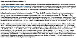
Complete examples of SBGN Entity Relationship Level 1 maps The following maps present complete examples of SBGN Entity Relationships representing biological processes. They by no mean exhaust the possibilities of SBGN Entity Relationship Level 1. Figure A.1 presents the different relations between the four entities involved in a Polymerase Chain Reaction (PCR). This examplifies the use of the entity, the logical operator or, the state variable “existence”, the unit of information, as well as the relationships interaction, assignment, necessary stimulation and absolute inhibition.
Figure A.1: Principle of the Polymerase Chain Reaction.
Figure A.2 on the next page depicts the effect of a depolarisation (dV) on the intracellular calcium, that binds to calmodulin, that itself binds to the calcium/calmoduline kinase II (CaMKII). The binding of calmodulin inhibits the folding of CaMKII monomer on itself, thus relieving the inhibition on the kinase activity. The phosphorylation of the glutamate receptors finally leads to the Long Term Potentiation (LTP) of the synapses. In addition, the map shows the effect of trans-phosphorylation on threonine 286, that makes the enzyme constitutively active, and on threonine 306, that renders the kinase insensitive to calmodulin, as well as the dimerisation of the kinase.
36
APPENDIX A. COMPLETE EXAMPLES OF SBGN ENTITY RELATIONSHIP LEVEL 1 MAPS37
Nature Precedings : doi:10.1038/npre.2009.3719.1 : Posted 4 Sep 2009
Figure A.2: Regulation of calcium/calmoduline kinase II effect on synaptic plasticity.
Appendix B
Reference card
Nature Precedings : doi:10.1038/npre.2009.3719.1 : Posted 4 Sep 2009
Print this summary of SBGN Entity Relationship symbols for a quick reference.
38
Nature Precedings : doi:10.1038/npre.2009.3719.1 : Posted 4 Sep 2009
APPENDIX B. REFERENCE CARD 39
Appendix C
Nature Precedings : doi:10.1038/npre.2009.3719.1 : Posted 4 Sep 2009
Issues postponed to future levels C.1
Domains, sites and motives SBGN Entity Relationship Level 1 does not currently provide structures to represent physical or functional subdivisions of entities. Nevertheless, it is clear that domains are important, and that people want, and need, to represent them. Domains would permit to define global and local auxiliary units, for instance global state variables (state of a ion channel pore) or local state variables (phosphorylation of a given subunit of a ion channel). The issue is not easy to resolve and the tentatives so far led to either problems of nesting or unsatisfactory identification and handling of global and local auxiliary units. Different solutions have been proposed, that can be grouped in two broad approaches: nesting and the subdivision. Both have advantages and disadvantages. Nesting is closer to the underlying, or conceptual, representation, and will probably be favored by computer scientists. Subdivision is closer to the physical structure of the entities and to what we draw in the back on an envelop and in a power-point presentation. It will likely be preferred by biologists. Designing a consistent and robust system will require a significant amount of work and discussion. Considering that the attribution of an auxiliary unit does not change the semantics of a map, and is more like a sophisticated annotation, but also that a map producer can currently use several entities to represent different domains, it was felt that the issue should be postponed to a further version of the language. Meanwhile, people interested can consult the relevant documents at http://sbgn.org/ER_development and participate to the discussion on
[email protected].
C.2
Generics and instances In SBGN Entity Relationship Level 1, an entity is represented only once. One cannot explicitely represent different instances of the “same” entity. Several instances can be infered from relationships acting in trans. However, one cannot generally express the fact that several relationships involving the same entity actually involve the same, or different, instances ot this entity. This problem is tied to the problem of generics. Indeed, if one discriminate between classes of instances, how can one represent, in the same map, the generic entity?
40
Bibliography [1] G. Di Battista, P. Eades, R. Tamassia, and I. G. Tollis. Graph Drawing: Algorithms for the Visualization of Graphs. Prentice Hall, New Jersey, 1998.
Nature Precedings : doi:10.1038/npre.2009.3719.1 : Posted 4 Sep 2009
[2] M. Kaufmann and D. Wagner. Drawing Graphs: Methods and Models, volume 2025 of Lecture Notes in Computer Science Tutorial. Springer, 2001.
41