Keywords: BPM, graphical notation, RALph, resource assignment ...... Physics of Notations by Moody [23] with the corresponding measurement in- strument by ...
RALph: A Graphical Notation for Resource Assignments in Business Processes⋆ Cristina Cabanillas1 , David Knuplesch2 , Manuel Resinas3 , Manfred Reichert2 , Jan Mendling1 , and Antonio Ruiz-Cort´es3 1
Vienna University of Economics and Business, Austria {cristina.cabanillas,jan.mendling}@wu.ac.at 2 Ulm University, Germany {david.knuplesch,manfred.reichert}@uni-ulm.de 3 University of Seville, Spain {resinas,aruiz}@us.es
Abstract. The business process (BP) resource perspective deals with the management of human as well as non-human resources throughout the process lifecycle. Although it has received increasing attention recently, there exists no graphical notation for it up until now that is both expressive enough to cover well-known resource selection conditions and independent of any BP modelling language. In this paper, we introduce RALph, a graphical notation for the assignment of human resources to BP activities. We define its semantics by mapping this notation to a language that has been formally defined in description logics, which enables its automated analysis. Although we show how RALph can be seamlessly integrated with BPMN, it is noteworthy that the notation is independent of the BP modelling language. Altogether, RALph will foster the visual modelling of the resource perspective in BPs. Keywords: BPM, graphical notation, RALph, resource assignment
1
Introduction
The Business Process (BP) resource perspective deals with the management of human as well as non-human resources throughout the process lifecycle [1]. The management of resources in this context involves the definition of assignments at design time, i.e. by querying those actors that are supposed to work on tasks, the allocation of resources at runtime, and the analysis of resource utilisation after execution for process improvement. While it is widely accepted that models and visual notations can be beneficial for system development [2], it is striking to note that a notation for modelling these aspects in an integrated way is still missing. The support of resource management in current process modelling approaches can be roughly categorised as follows. On the one hand, languages like Business ⋆
This work was funded by the Austrian Research Funding Association (FFG) and Science Fund (FWF), the German Research Foundation (DFG), the European Commission (FEDER), the Spanish and the Andalusian R&D&I programmes (grants 845638 (SHAPE), I743, RE 1402/2-1 (C3 Pro), TIN2012-32273 (TAPAS), P12-TIC1867 (COPAS), TIC-5906 (THEOS)).
2
C. Cabanillas et al.
Process Model and Notation (BPMN) [3] emphasise modelling of the control flow and data in its graphical notation. Resource assignments can be expressed in a rather basic fashion visually, with partial extensions in structured but nonvisual attributes. On the other hand, implementations like the YAWL system [4] provide a rich support for the resource perspective, but not as part of the visual notation. A few works have contributed towards a better integration of a visual notation for defining resource assignments with extensive semantics recently [5, 6]. Still, they expose gaps towards a full visual support. In this paper, we want to bridge this gap by introducing RALph, a graphical notation for defining the assignments of human resources to BP activities. RALph has the following characteristics: (i) It is expressive. In particular, it allows defining all the resource selection conditions covered by the workflow resource patterns [7] as well as those we discovered in a real scenario from the healthcare domain. (ii) Resource assignments specified with RALph can be automatically analysed. In turn, this enables automatic answers to questions such as “Is the BP consistent regarding the use of resources?” or “Which activities may Mr. B perform in the context of BP X?”. This is achieved by defining the semantics of RALph through its semantic mapping to Resource Assignment Language (RAL) [5], a textual language for resource assignment whose formal semantics was defined in description logics. (iii) It is independent of any BP modelling language. For that, it can be seamlessly integrated with existing notations (e.g., BPMN), as demonstrated with a proof-of-concept prototype we developed. The remainder of the paper is structured as follows: Section 2 describes a real scenario that serves as use case throughout the paper, and evidences the need of a graphical notation for resource specification in Business Process Management (BPM) by studying related work. Section 3 introduces RALph’s graphical notation and its formal syntax. Section 4 describes RALph’s formal semantics. Section 5 discusses expressiveness issues and presents RALph’s integration capabilities with existing tools. Finally, Section 6 concludes this work and gives an outlook of future work.
2
Background
In this section, we discuss the background of our research. Section 2.1 presents the running example that we use in this paper. Section 2.2 discusses prior work related to resource specification. Section 2.3 summarises requirements for a graphical notation for resource assignment. 2.1
Running Example
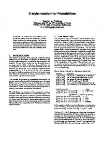
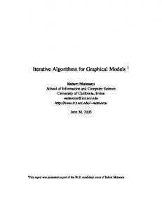
Throughout this paper, we will use the process of patient examination as running example. Figure 1 shows this process modelled in BPMN according to the description provided by the Women’s Hospital of Ulm. Furthermore, we refer to the organisational model of this hospital that is shown in Figure 2 [8, 9]. In it, the rectangles with rounded corners represent organisational units that
RALph: A Graphical Notation for Resource Assignments in BPs
3
Appointment: Date Patient info Sample type Ward
No
Release patient
Yes
No
Additional example required?
Examine patient
Order examination & follow-up treatment
Yes
Inform about risks
Make appointment
Prepare examination
Take sample
Patient agrees?
Request form: Patient info Analysis required Laboratory
No
Perform follow-up treatment
Describe therapy
Make diagnosis
Validate results
Validate sample state
Yes
Analyse sample
Sample OK?
Send sample
Fig. 1: Process of patient examination Woman’s hospital Outpatient department
Ward Intensive care unit
Ward 1
Postnatal ward 1
...
Function area Laboratory department
...
Endocrinology Mrs. A
Ward physician
Mr. B Mrs. E Mrs. F
Nurse Mrs. G
Mr. C
Mr. I
Mrs. D
Mrs. K
Mr. H
Mr. M Mrs. N
...
Surgery department Molecular endocrinology
Outpatient physician
Mr. L
Lab physician
Nurse
Mr. P
MTA
Tumor markers
... ...
...
Mr. R Mr. S Mrs. T
Mrs. O
...
Mrs. U
Fig. 2: Organisational model
are structured hierarchically; rectangles with straight corners are hierarchies of organisational positions within the units; and ellipses represent people1 that occupy the positions defined. The examination process can be summarised as follows. The process starts when the female patient is examined by an outpatient physician, who decides whether she is healthy or needs to undertake an additional examination. In the former case, the physician fills out the examination form and the patient can leave. In the latter case, an examination and follow-up treatment order is placed by the physician who additionally fills out a request form. Beyond information about the patient, the request form includes details about the examination requested and refers to a suitable lab. Furthermore, the outpatient physician informs the patient about potential risks. If the patient signs an informed consent and agrees to continue with the procedure, a delegate of the physician arranges an appointment of the patient with one of the wards. The latter is then respon1
Please, note that due to privacy issues the names have been anonymised.
4
C. Cabanillas et al.
sible for taking a sample to be analysed in the lab later. Before the appointment, the required examination and sampling is prepared by a nurse of the ward based on the information provided by the outpatient section. Then, a ward physician takes the sample requested. He further sends it to the lab indicated in the request form and conducts the follow-up treatment of the patient. After receiving the sample, a physician of the lab validates its state and decides whether the sample can be used for analysis or whether it is contaminated and a new sample is required. After the analysis is performed by a medical technical assistant of the lab, a lab physician validates the results. Finally, a physician from the outpatient department makes the diagnosis and prescribes the therapy for the patient. Note that information about resources is missing in Fig. 1, since BPMN swimlanes are not expressive enough to cope with the resource assignment conditions required. For instance, they do not allow indicating that activities Examine patient, Release patient and Order examination & follow-up treatment must be executed by the same physician (i.e., binding of duties). It is neither possible to express that activity Make appointment must be performed by a delegate of the physician who examined the patient, nor that the performer of activity Validate sample state must belong to the lab indicated in the request form, which is dynamic information that is only known at run time. 2.2
Related Work
The study of related work reveals some gaps in resource assignment in BPM. Several metamodels [10, 11] and expressive resource assignment languages [5, 12] have been developed, but they do not provide any graphical representation of the concepts they handle and the resource selection conditions they allow for. Some of them provide display notations in the form of user interfaces that help non-technical users to define the conditions [4, 13], but these are not visualised together with the elements of the BP model. The main drawback of the graphical notations proposed so far is that they lack formal semantics, which makes them inappropriate for automated resource analysis in BP models. This is the case of the swimlanes offered by the defacto standard BPMN [3]. Event-driven Process Chains (EPCs) [14] also allow for the graphical assignment of organisational entities to process activities, but semantics are not defined. Some approaches have been developed to overcome this drawback. However, they either present a lack of expressive power regarding the conditions for resource selection they allow defining, or have been developed for specific BP modelling notations, or both. The workflow resource patterns [7] (see also Section 5.1) are used to assess the former criterion. Business Activities [6] is a Role-based access control (RBAC) [15] extension of Unified Modeling Language (UML) activity diagrams to define separation of duties and binding of duties between the activities of a process. Some ad-hoc analysis mechanisms have been developed for them as well. However, their scope does not cover resource selection conditions based on other organisational entities, people’s skills or runtime
RALph: A Graphical Notation for Resource Assignments in BPs
5
information. Several approaches extended the BPMN metamodel to graphically define specific types of conditions along with the swimlanes or with process activities. For instance, Wolter and Schaad introduced access-control constraints in BPMN models through an extension based on authorisation constraints [16]. Awad et al. [17] and Stroppi et al. [18], in turn, developed extensions that cover all the assignment patterns defined by the workflow resource patterns. In all these approaches, however, the definition of the resource selection conditions is mainly done textually, though graphically associated to BPMN elements, e.g. by making use of BPMN text annotations or group artifacts. 2.3
Requirements for a Graphical Resource Assignment Notation
We have studied the related work according to well-defined criteria in order to discover the gaps that should be bridged. Table 1 depicts the result of the evaluation, where ✓ indicates full support for a criterion, ∼ indicates partial support, and − indicates no support. Specifically, the criteria included in the comparison framework are the following: Extent of language specification. The syntactic, semantic and pragmatic perspectives of the language for resource assignment are evaluated. In particular, we have checked whether it has formal syntax and semantics, and whether there is a graphical notation to model the resource selection conditions together with the other elements of a BP model. Extent of domain concepts. The expressiveness of the graphical notation is assessed according to the workflow resource patterns [7], which have been used as evaluation framework to assess the expressiveness of a number of proposals on resource assignment in BPM [11, 17, 19, 6, 20]. Specifically, we use the creation patterns, as they are related to resource selection. These patterns include: Language Specification Syntax Semantics Graph. HRMM [10] − ✓ − Team [11] − ✓ − RAL[5] ✓ ✓ − CSL[12] ✓ ✓ − YAWL[4] ✓ ✓ ∼ XACML N.[13] ✓ ✓ ∼ BPMN[3] ✓ − ✓ EPCs[14] ✓ − ✓ Business A.[6] ✓ ✓ ✓ BPMN E.[16] ✓ ✓ ∼ BPMN E.[17] ✓ ✓ ∼ BPMN E.[18] ✓ ✓ ∼ Approach
Entity ∼ ∼ ✓ ∼ ✓ ∼ ✓ ✓ ∼ ∼ ∼ ✓
AC − ✓ ✓ ✓ ✓ − − − ✓ ✓ ✓ ✓
Domain Concepts Capability Deferred − − ✓ − ✓ ✓ − − ✓ ✓ ✓ − − − − − − − − − ✓ − ✓ ✓
Table 1: Study of resource assignment approaches
History − − ✓ − ✓ − − − − ✓ ✓ ✓
Reuse ✓ ✓ ✓ ✓ − ✓ − − − − − −
6
C. Cabanillas et al.
– Direct Allocation is the ability to specify at design time the identity of the resource that will execute a task. – Role-Based Allocation is the ability to specify at design time that a task can only be executed by resources that correspond to a given role. – Organisational Allocation is the ability to offer or allocate activity instances to resources based their organisational position and their relationship with other resources. – Separation of duties is the ability to specify that two tasks must be allocated to different resources in a given BP instance. – Case Handling is the ability to allocate the activity instances within a given process instance to the same resource. – Retain Familiar is the ability to allocate an activity instance within a given BP instance to the same resource that performed a preceding activity instance, when several resources are available to perform it. This pattern is also known as binding of duties. – Capability-Based Allocation is the ability to offer or allocate instances of an activity to resources based on their specific capabilities. – Deferred Allocation is the ability to defer specifying the identity of the resource that will execute a task until run time. – History-Based Allocation is the ability to offer or allocate activity instances to resources based on their execution history. For the sake of brevity, in Table 1 the first three patterns have been grouped as entity-based assignments, and the three subsequent patterns have beed grouped as access-control assignments. Note that creation patterns Authorisation and Automatic Execution are not on the list. The former is excluded since it is not related to the definition of conditions for resource selection, and the latter since it is not related to the assignment language and is inherently supported by all Business Process Management Systems (BPMSs). Extent of reusability. We have also checked whether the current graphical notations for resource assignment are independent of any BP modelling language. Independent notations are likely to be applicable in different domains along with different existing notations.
3
RALph: Resource Assignment Language Graph
This section presents the RAL graph (RALph) visual notation for specifying resource assignments in BP models. RALph represents resources as different kinds of entities instead of using pools and lanes like in BPMN [3]. In turn, resource assignments are expressed by connectors, which either link resources to activities or link activities among each other in order to express access-control constraints (i.e., separation and binding of duties). The semantic concepts underlying the elements (i.e., entities and connectors) of RALph have been identified based on the experience we gained in the context
RALph: A Graphical Notation for Resource Assignments in BPs
7
of (textual) resource assignment languages [5] and case studies we applied in the healthcare domain [8, 9, 21]. In turn, we iteratively elaborated their visual representation (cf. Fig. 3) in eleven steps and during discussions with domain experts. 3.1
Graphical Notation
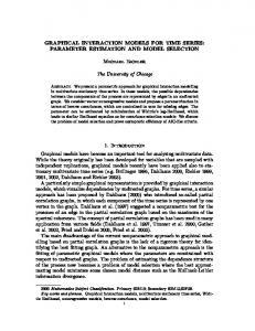
The RALph graphical notation provides various visual elements (i.e., entities and connectors) that enable the visual modelling of resource selection conditions in process models (cf. Fig. 3). For this purpose, activities may either be connected with resource entities using the resource assignment connector as well as hierarchy connectors or with other activities using history connectors. The resource assignment connector enables the explicit specification of responsibilities by connecting resource or capability entities to activities. RALph provides four resource entities that cover persons, roles, positions, and organizational units. In order to refer to a particular resource, its name must be specified as a label on them. In turn, unlabeled resource entities are wildcards to be further restricted through data-driven connectors, which use fields of data objects to specify the name of the resource. In addition, roles can be linked with organizational units using the resource assignment connector in order to select only those actors that play a specific role within a specific unit of an organisation. Finally, capability entities refer to persons having a particular capability or skill. RALph assumes that the organisation is structured hierarchically based on positions, similarly to other approaches [7, 5, 20]. Hence, the hierarchy connectors apply hierarchical relationships and assign an activity to the super- or subordinated persons of a specific position, which is specified using the position resource entity. One may want to refer to direct reporting, i.e. to the positions immediately superior in the hierarchy, or to transitive reporting, i.e. scaling up in the hierarchy by transitivity. In order to distinguish between them, hierarchy connectors may either use single arrow heads (direct) or doubled ones (transitive). Finally, RALph provides four different kinds of history connectors. They assign an activity to those actors that have been responsible for the execution of another activity, which is connected by a connector that ends up with an empty circle. The activity referenced represents an activity instance (i) in the context of the same process instance (solid line), (ii) the same or any previous process instance (solid line and log symbol), (iii) any previous process instance (dashed line and log symbol), or (iv) any process instance that was executed in a specified period of time (dashed line and calendar symbol). RALph applies an AND-semantics, i.e., all the resource selection conditions defined for an activity must be considered in the assignment. Nonetheless, diamonds may be used to express that only one of the conditions defined needs to be satisfied in order to assign resources to the activity. In order to specify negations, connectors can be crossed-out (cf. negated assignment/connector in Fig. 3). Fig. 4 applies the RALph language to the patient examination process of our running example (cf. Sect. 2.1 and Fig. 1). For example, Fig. 4 assigns position
8
C. Cabanillas et al. Resource Entities
Negated Assignment/ Connector
Simple Assignment
Alternative Connector
History Connectors
Activity A
Organizational Unit
University of Somewhere
Mrs. One
Mrs. One
Mr. Two
=
Activity B
the same process instance
Activity Activity Activity
Activity A
A ph
Position
Capability Entity
Hierarchy Connectors
Activity B
Data-Driven Connector Activity A
Data object
log
=
Activity B
any previous process instance
Data field
Activity A
Capability
=
the same or any previous process instance
Data field
Person
log
23-25 Sept 14
= =
Activity B
reports
can delegate
Role
Activity
any process instance within a specified period
Fig. 3: The RALph language
outpatient physician of unit outpatient department (cf. Fig. 2) to task examine patient. Furthermore, a history connector expresses that the same person is also assigned to task release patient. In turn, a hierarchy connector is applied in order to specify that a delegate of the outpatient physician (i.e., someone to whom the physician can delegate work) is responsible for task make appointment. Finally, an example of a data-driven connector refers to field ward of data object appointment in order to specify the organizational unit, which is responsible for taking the sample. In particular, a nurse and a ward physician of the respective ward are assigned to the tasks prepare examination and take sample and subsequent steps. 3.2
Formal Specification
In order to provide a clear syntax as well as to enable the specification of a formal semantics for RALph, this section introduces a set-based definition of RALph. Since RALph extends process models, first of all, Definition 1 provides a fundamental definition of the latter. Note that Definition 1 abstracts from those details of process models that are not relevant for the formal specification of RALph. For example, types of activities are not specified. Furthermore, all gateways and events, respectively, are combined in one set. Definition 1 (Process Model). A process model P M is a tuple P M = (A, G, E, D, −▸, ⋯>) where – A is a set of activities, – G is a set of gateways,
RALph: A Graphical Notation for Resource Assignments in BPs
9
Appointment: Outpatient physician
Date Patient info Sample type Ward
=
Examine patient
can delegate
Additional example required?
Ward physician
Nurse
Order examination & follow-up treatment
Yes
[Ward]
No
No
Release patient
Ward
Yes
Inform about risks
Make appointment
Prepare examination
Take sample
Patient agrees?
Outpatient department
=
=
Request form:
=
Patient info Analysis required Laboratory
=
= Perform follow-up treatment
Laboratory No
Describe therapy
Make diagnosis
Validate results
Analyse sample
Yes
Validate sample state
Sample OK?
Send sample Outpatient physician
MTA Physician
Physician [Laboratory]
Fig. 4: Process of patient examination with RAL graph
– – – –
E is a set of events, D is a set of data objects, −▸ ⊆ (A ∪ G ∪ E) × (A ∪ G ∪ E) is a sequence flow relation, and ⋯> ⊆ (A × D) ∪ (D × A) is an information flow relation.
Based on Definition 1, we formally specify RALph in Definition 2. Specifically, Definition 2 includes four sets of resource entities and one set for capability entities. In addition, it comprises six sets specifying the different kinds of connectors and, finally, four functions labeling and annotating entities and connectors. Definition 2 (RAL Graph (RALph)). Let P M = (A, G, E, D, −▸, ⋯>) be a process model (cf. Definition 1). Further, let L be a set of labels and � be the empty string. Then: A RAL graph (RALph) for P M is a tuple Ψ = (P, S, U, R, C, ◇, —, →, →, ⟜ p, lbl, hr, hs, σ) where ⊸ – – – – – – – –
P is a set of person entities, S is a set of position entities, U is a set of organizational unit entities, R is a set of role entities, C is a set of capability entities, ◇ is a set of alternative connectors, — ⊆ (A∪◇)×(P ∪S ∪U ∪R∪◇)∪(S ×U ) are resource assignment connectors, → ⊆ ((A ∪ ◇) × S) ∪ (S × (A ∪ ◇)) are hierarchy connectors, where function hr ∶ → Ð→ {d, t} × {rep, del} specifies whether a hierarchy connector is direct (d) or transitive (t), and whether it expresses the duty to report work (rep) or the power to delegate work (del) to people according to their positions,
10
C. Cabanillas et al.
– ⟜ ⊆ (A ∪ ◇) × A are history connectors, where function p ⊸ hs ∶ ⟜ p Ð→ {s, p, sp} ∪ T specifies whether a history connector refers to ⊸ the same (s) process instance, to all previous (p) process instances, the same and all previous (sp) process instances, or to all process instances satisfying a temporal constraint t ∈ T , – → ⊆ D × (P ∪ S ∪ U ∪ R) are data-driven connectors, – lbl ∶ P ∪S ∪U ∪R∪C ∪ → Ð→ L∪{�} labels person, role, position and organizational unit entities as well as capability entities and data-driven connectors either with the empty string � or the name of the resource, capability or with the data field read by the data-driven connector, – σ ∶ —∪ →∪ ⟜ p Ð→ {1, ¬} specifies whether the connectors are unmodified ⊸ ( 1) or negated (¬) - i.e., crossed out in the graphical notation. Note that Definition 2 specifies how the elements of a RALph specification can be connected with each other and with elements of the corresponding process model. However, Definition 2 still allows for ambiguities and conflicts (e.g., two or more data-driven connectors may be connected to the same resource entity or cycles of history connectors may occur). In order to enable the specification of correctness criteria dealing with these issues, Definition 3 introduces different sets of nodes and edges as well as a special subgraph of a RALph model. Definition 3 (Nodes, Edges and Subgraphs of a RAL Graph). Let P M = (A, G, E, D, −▸, ⋯>) be a process model (cf. Definition 1) and let Ψ = (P, S, U, R, C, ◇, —, →, →, ⟜ p, lbl, hr, hs, σ) be a RAL graph for P M . Then: ⊸ – NΨ ∶= A∪O ∪P ∪S ∪U ∪R∪C ∪◇ is the set containing all nodes of RAL graph Ψ , including the activities and data objects of the related process model, – —+ ∶= — ∪ → ∪ ⟜ p are the extended resource assignment connectors of RAL ⊸ graph Ψ that also include hierarchy and history connectors, – —T ∶= {(n1 , n2 ) ∈ —∣n2 ∈ T } ⊆ — are the resource connectors, which are connected to resources of entity type T ∈ {P, S, U, R, C} (e.g., all elements of —P are connected to person entities), – GiΨ ∶= (A ∪ ◇, {(n1, n2) ∈ —+ ∣n1 , n2 ∈ A ∪ ◇}) is the inner subgraph of Ψ , which is derived from Ψ after removing all resource entities and connected edges. Note that GiΨ only includes resource and history connectors. Based on Definition 3, we can specify correctness criteria for RALph. In particular, we specify whether or not a RAL graph is well-formed as follows. Definition 4 (Well-formed RAL Graph). Let P M = (A, G, E, D, −▸, ⋯>) be a process model (cf. Definition 1) and let Ψ = (P, S, U, R, C, ◇, —, →, →, ⟜ p, lbl, hr, hs, σ) be a RAL graph for P M (cf. Def⊸ inition 2). Then, Ψ is well-formed, iff each of the following constraints holds: C1: Resource entities must be either labeled or be target of a data-driven connector; i.e., ∀n ∈ P ∪ S ∪ U ∪ R ∪ C exactly one of the following conditions must be true:
RALph: A Graphical Notation for Resource Assignments in BPs
11
● lbl(n) ≠ �, ● ∃(f, n) ∈ →. C2: Data-driven connectors must be always labeled; i.e., ∀d ∈ → ∶ lbl(d) ≠ �, C3: Resource entities must not be target of more than one data-driven connector; i.e., ∀n ∈ P ∪ S ∪ U ∪ R ∶ ∣{e ∈ →∣e = (f, n)}∣ ≤ 1 C4: There exists no cycle of history connectors; i.e., GiΨ is acyclic. Note that Definition 4 does only ensure that a RAL Graph itself is wellformed. However, the interplay of sequence flow, information flow and resource assignments might cause other errors. Further, note that the italic labels in square brackets on the organizational units ward and laboratory in Fig. 4 constitute comments that are only used to ease understanding. Therefore, they are not part of the RAL graph; i.e., for both, labeling function lbl returns the empty string � (cf. C1 in Definition 4).
4
RALph Semantics
We provide RALph with a well-defined semantics to enable its automated analysis and verification. In particular, we establish a semantic mapping to an existing textual resource assignment language called RAL [5]. RAL presents the following advantages: (i) It is expressive regarding the types of resource selection conditions that can be defined; (ii) It is independent of any BP modelling language; and (iii) Its semantics are well-defined, which enables automated analyses of RAL expressions [5]. In addition, RAL’s syntax is close to natural language to improve its readability. In the following, we textually describe the resource assignments for some activities2 of the running example (cf. Fig. 4) together with the expressions that define them in RAL. Release patient. The patient is released by the physician who examined her. IS ANY PERSON responsible for ACTIVITY Examine patient
Make appointment. An appointment is made by checking availability with a delegate of the ward physician. CAN HAVE WORK DELEGATED BY POSITION Ward physician
Prepare examination. The required examination is prepared by a nurse of the ward indicated in the request form. (HAS POSITION NURSE) AND (HAS UNIT IN DATA FIELD Appointment.Ward)
In the following, we define the mapping of RALph to RAL as a mapping function µ ∶ A Ð→ RALExpr that maps the resource assignment specified by RALph to any activity a ∈ A to a RAL expression. However, we first must introduce three auxiliary mappings, namely: η, ρ and ρn The label mapping function η ∶ P ∪ S ∪ U ∪ R Ð→ L ∪ LD maps each resource entity to either its label or the data field that specify its name. LD is the set obtained as the result of prefixing IN DATA FIELD to all l ∈ L. Specifically, for all x ∈ P ∪ S ∪ U ∪ R: 2
Due to space limitations, we have selected a representative subset of assignments.
12
C. Cabanillas et al.
– lbl(x) ≠ � ⇒ η(x) = lbl(x) – ∃(o, x) ∈ → ⇒ η(x) = IS PERSON IN DATA FIELD lbl(o, x) The resource selection condition mapping function ρ ∶ —+ Ð→ RALExpr maps resource selection conditions specified by RALph connectors to RAL expressions. Specifically: – ∀(o, p) ∈ —P ⇒ ρ(o, p) = IS η(p) – ∀(o, s) ∈ —S ⇒ ρ(o, s) = HAS POSITION η(s) – ∀(o, r) ∈ —R : ● ∃(r, u) ∈ —, u ∈ U ⇒ ρ(o, r) = HAS ROLE η(r) IN UNIT η(u) ● Otherwise, ρ(o, r) = HAS ROLE η(r) – ∀(o, u) ∈ —U , o ∈/ R ⇒ ρ(o, u) = HAS UNIT η(u) – ∀(o, c) ∈ —C ⇒ ρ(o, c) = HAS CAPABILITY lbl(s) – ∀(o, s) ∈ →, then: ● hr(o, s) = (d, rep) ⇒ ρ(o, s) = DIRECTLY REPORTS TO POSITION s ● hr(o, s) = (t, rep) ⇒ ρ(o, s) = REPORTS TO POSITION s ● hr(o, s) = (t, del) ⇒ ρ(o, s) = CAN DELEGATE WORK TO POSITION s – ∀(o, a) ∈ ⟜ ⊸, then: p ● hr(o, a) = s ⇒ ρ(o, a) = IS ANY PERSON responsible for ACTIVITY a ● hr(o, a) = p ⇒ ρ(o, a) = IS ANY PERSON responsible for ACTIVITY a IN ANOTHER INSTANCE
● hr(o, a) = sp ⇒ ρ(o, a) = IS ANY PERSON responsible for ACTIVITY a IN ANY INSTANCE
● hr(o, a) = {t1 , t2 }, {t1 , t2 } ∈ T ⇒ ρ(o, a) = IS ANY PERSON responsible for ACTIVITY a FROM t1 TO t2
– ∀(o, ◇) ∈ — ⇒ ρ(o, ◇) = (ρn (◇, x1 )) OR ... OR (ρn (◇, xn )), for all (◇, xi ) ∈ + — with 1 ≤ i ≤ n. The negation mapping function ρn ∶ —+ Ð→ RALExpr extends mapping function ρ by taking negations into account. Specifically, ∀(o, x) ∈ —+ : – σ(o, x) = ¬ ⇒ ρn (o, x) = NOT (ρ(o, x)) – σ(o, x) = 1 ⇒ ρn (o, x) = ρ(o, x) Finally, since RALph applies an AND-semantics for all resource selection conditions defined for an activity, the mapping of RALph to RAL µ ∶ A Ð→ RALExpr can be defined as follows: µ(a) = (ρn (a, x1 )) AND ... AND (ρn (a, xn )), for all (a, xi ) ∈ —+ with 1 ≤ i ≤ n.
5
Evaluation
The evaluation of RALph described below is two-fold. On the one hand, we assess its expressive power using the workflow resource patterns as evaluation framework. On the other hand, its usage with existing BP modelling notations has been tested by integrating it into a platform that uses BPMN for process modelling. Its applicability was already shown in Fig. 4 by modelling the resource assignments defined in the real scenario from Section 2.1.
RALph: A Graphical Notation for Resource Assignments in BPs
5.1
13
Support for the Workflow Resource Patterns
In the following, we describe how RALph covers all the creation patterns, which were used for the evaluation of existing approaches in Section 2.3: – Direct Allocation. Connection of resource entity Person to an activity. – Role-Based Allocation. Connection of resource entity Role to an activity. – Deferred Allocation. Connection of a data object to any resource entity with a data-driven connector: e.g., for activities Prepare examination, Take sample and Analyse sample (cf. Fig. 4), the organisational unit is indicated in a data field. In particular, the value of the data field selected is only known at run time. – Separation of duties. Connection of two activities with a history connector, which indicates that the activity instances belong to the same BP instance, and crossing it out to indicate it is a negated assignment. For example, it is expressed like the assignments for activities Release patient, Inform about risks and Send sample (cf. Fig. 4) but using a negated connector instead of the simple one. – Case Handling. To implement this pattern with RALph, we should specify a separation of duties for all the activities of a process. – Retain Familiar. Connection of two activities with a history connector that indicates that the activity instances belong to the same BP instance: e.g., activities Release patient and Inform about risks (cf. Fig. 4) have a binding of duties with activity Examine patient. – Capability-Based Allocation. Connection of a capability entity to an activity. – History-Based Allocation. Connection of two activities with a history connector that indicates that the referenced activity belongs to (i) the same or any previous BP instance, (ii) a previous BP instance, or (iii) any BP instance executed within a specific period of time. – Organisational Allocation. Connection of resource entity Position to an activity, e.g. in activities Examine patient and Make diagnosis of Fig. 4. 5.2
Implementation
We provide a graphical editor for RALph diagrams at http://www.isa.us.es/ cristal. This editor is based on Oryx [22], which is an open–source platform to build web–based diagram editors. Oryx provides native support for several graphical notations such as BPMN, and allows for the definition of new graphical notations by means of the so–called stencil sets. Consequently, RALph has been implemented as an Oryx stencil set that extends the Oryx–native BPMN stencil set with the symbols described in this paper. Figure 5 depicts a screenshot of RALph web–based editor.
6
Conclusions and Future Work
In this paper we have introduced RALph, a graphical notation for defining resource assignments in BP models. RALph is more expressive than existing approaches. Specifically, it deals with real selection conditions as discovered, e.g.,
14
C. Cabanillas et al.
Fig. 5: RALph web–based editor
in the healthcare domain. Furthermore, it provides support for all the creation patterns related to resource selection. It also has formal semantics provided by a mapping to RAL [5], which uses description logics as semantic formalism and as a means to automate the analysis of the BP resource perspective. Hence, RALph enables not only the graphical representation of resource assignments, but also their automated analysis at design time to discover inconsistencies a-priori, as well as at run time to detect potential problems with resource allocation (e.g., a lack of performers for some activity given previous allocations). This bridges the existing gap in BP modelling notations for the resource perspective and eases the way resources are handled by non-technical users. In addition, RALph is independent of any BP modelling notation. There are several directions for future work. First, we want to assess RALph’s expressive power with more use cases. Second, we want to evaluate its understandability and learnability by conducting experiments with end users. The Physics of Notations by Moody [23] with the corresponding measurement instrument by Figl et al. [24] provide the basis for that work. Finally, we want to extend the notation to be able to consider several degrees of responsibilities for a process activity beyond the resource responsible for its execution (i.e., the performer of the work). For instance, there may be a resource in charge of approving the work performed, or there may be resources that must be informed when the activity has been completed (cf. the Generic Human Roles defined in BPEL4People [19] and RACI matrices [25]). For these involvements, it should also be possible to specify resource selection conditions.
References 1. M. Dumas, M. L. Rosa, J. Mendling, and H. A. Reijers, Fundamentals of Business Process Management. Springer, 2013.
RALph: A Graphical Notation for Resource Assignments in BPs
15
2. J. Whittle, J. Hutchinson, and M. Rouncefield, “The State of Practice in ModelDriven Engineering,” IEEE Software, vol. 31, no. 3, pp. 79–85, 2014. 3. OMG, “BPMN 2.0,” recommendation, OMG, 2011. 4. W. M. P. van der Aalst and A. H. M. ter Hofstede, “YAWL: Yet Another Workflow Language,” Inf. Syst., vol. 30, no. 4, pp. 245–275, 2005. 5. C. Cabanillas, M. Resinas, and A. R. Cort´es, “Specification and Automated DesignTime Analysis of the Business Process Human Resource Perspective,” Inf. Syst., p. In press., 2015. 6. M. Strembeck and J. Mendling, “Modeling process-related RBAC models with extended UML activity models,” Inf. Softw. Technol., vol. 53, pp. 456–483, 2011. 7. N. Russell, A. ter Hofstede, D. Edmond, and W. M. P. van der Aalst, “Workflow Resource Patterns,” tech. rep., BETA, WP 127, Eindhoven Univ. of Tech., 2004. 8. I. Konyen, M. Reichert, and B. Schultheiss, “Prozessentwurf eines Ablaufs im Labor,” tech. rep., Ulm University, 1996. 9. F. Semmelrodt, “Modellierung klinischer Prozesse und Compliance Regeln mittels BPMN 2.0 und eCRG,” Master’s thesis, University of Ulm, 2013. 10. A. Koschmider, L. Yingbo, and T. Schuster, “Role Assignment in Business Process Models,” in BPM Workshops, LNCS, pp. 37–49, Springer, 2012. 11. W. M. P. van der Aalst and A. Kumar, “A Reference Model for Team-enabled Workflow Management Systems,” Data Knowl. Eng., vol. 38(3), pp. 335–363, 2001. 12. E. Bertino, E. Ferrari, and V. Atluri, “The specification and enforcement of authorization constraints in workflow management systems,” ACM Trans. Inf. Syst. Secur., vol. 2, pp. 65–104, February 1999. 13. B. Stepien, A. P. Felty, and S. Matwin, “A Non-technical User-Oriented Display Notation for XACML Conditions,” in MCETECH, vol. 26 of LNBIP, pp. 53–64, Springer, 2009. 14. W. van der Aalst, “Formalization and verification of event-driven process chains,” Information and Software Technology, vol. 41, no. 10, pp. 639–650, 1999. 15. D. F. Ferraiolo and et al., “Proposed NIST standard for role-based access control,” ACM Trans. Inf. Syst. Secur., vol. 4, pp. 224–274, August 2001. 16. C. Wolter and A. Schaad, “Modeling of Task-Based Authorization Constraints in BPMN,” in BPM’07, vol. 4714 of LNCS, pp. 64–79, Springer, 2007. 17. A. Awad, A. Grosskopf, A. Meyer, and M. Weske, “Enabling Resource Assignment Constraints in BPMN,” tech. rep., BPT, 2009. 18. L. J. R. Stroppi, O. Chiotti, and P. D. Villarreal, “A BPMN 2.0 Extension to Define the Resource Perspective of Business Process Models,” in CIbS’11, 2011. 19. “WS-BPEL Extension for People (BPEL4People),” tech. rep., OASIS, 2009. 20. M. Adams, YAWL v2.3-User Manual, 2012. 21. F. Semmelrodt, D. Knuplesch, and M. Reichert, “Modeling the Resource Perspective of Business Process Compliance Rules with the Extended Compliance Rule Graph,” in BPMDS’14, vol. 175 of LNBIP, pp. 48–63, Springer, 2014. 22. G. Decker, H. Overdick, and M. Weske, “Oryx - An Open Modeling Platform for the BPM Community,” in BPM’08, pp. 382–385, 2008. 23. D. L. Moody, “The Physics of Notations: Toward a Scientific Basis for Constructing Visual Notations in Software Engineering,” IEEE Trans. Software Eng., vol. 35, no. 6, pp. 756–779, 2009. 24. K. Figl, J. Recker, and J. Mendling, “A study on the effects of routing symbol design on process model comprehension,” Decision Support Systems, vol. 54, no. 2, pp. 1104–1118, 2013. 25. M. Smith, J. Erwin, and S. Diaferio, “Role And Responsibility Charting (RACI),” in Project Management Forum (PMForum), 2005.