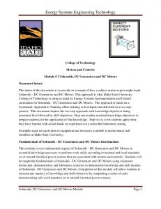
Apr 5, 2010 - Definitions. Risk. Management. Customer. Interaction. System. Architecture. Technical Specification. Mgt & Coordination. Systems. Integration.
Systems Engineering and Integration Technology Transition to Target (T4) Joseph J. Simpson April 5th, 2010
© 2010 Joseph J Simpson, System Concepts, LLC
1
Overview Definitions Systems Engineering Approach Systems Integration Approach Organizational - People Program, Project and Process Technology Major Systems Engineering Process Technology Development Activities and Process Science and Technology Streams of Change Science and Technology Development Technology Target Analysis Technology Transition Example Rapid Technology Development Summary © 2010 Joseph J Simpson, System Concepts, LLC
2
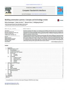
Systems Engineering - Definition Systems Engineering (SE) is an interdisciplinary approach and means to enable the realization of successful systems.
Project Systems Engineering System Architecture
Task Definitions
Project Planning & Control Project Planning
Risk Management
Technical Specification Mgt & Coordination Systems Integration
Resource Allocation
Customer Interaction
Financial Contract Management
(Adapted from INCOSE SE Handbook, v. 3.2, January 2010) © 2010 Joseph J Simpson, System Concepts, LLC
3
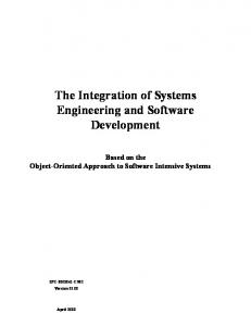
Systems Integration - Definition *“Systems Integration – is the art and science of facilitating the marketplace of ideas that connects the many separate solutions into a system solution.” Mission Function Level 1
MF
MF
Mission:
Level 2
A property of the system function that determines how well the mission function is performed
MF1
+
+
MF2
MF3
MF
MF3.1 MF3.2 MF3.3
MF
Explosives Detection
Level 3
MF1.1 MF1.2 MF1.3
Operational Effectiveness
+
MF2.1 MF2.2
+
Risk Level 1
SF Level 2
SF1
+
SF2
+
SF3
A property of the mission SF function, the system function and the system SF architecture
Operational Suitability
Life Cycle Cost
Properties of the system architecture Level 1
SA
Level 3
SF1.1 SF1.2 SF1.3
+
SF2.1 SF2.2
+
SF3.1 SF3.2 SF3.3
SF
SA
Level 2
SA1
System Function
+
SA2
+
SA3
SA
SA3.1 SA3.2 SA3.3
SA
Level 3
SA1.1 SA1.2 SA1.3
+
SA2.1 SA2.2
+
System Architecture
*Jeffrey O. Grady, System Integration, 1994 © 2010 Joseph J Simpson, System Concepts, LLC
Candidate Systems: • Dogs • Technical Sensors • Behavioral Observation • Combination of above 4
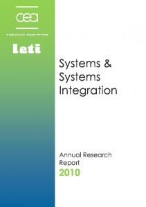
Technology Readiness Levels - Definition Technology Readiness Levels (TRLs) – provide a scale composed of nine measures that indicate a program's risk and potential for success. Technology metrics are associated only with technology attributes and characteristics TRL1
(in laboratory)
TRL4
Examples • Weight (Mass, Vibration) • Processing capacity • Processing speed • Volume • Power consumption • Resolution © 2010 Joseph J Simpson, System Concepts, LLC
Technology metrics are more likely to be associated with the performance of a given mission in a given environment TRL5
(in relevant environment)
TRL9
For Μ [Mission Accomplishment] on a scale of 0 to 1
Μ = ƒ ∑ (Technical Performance Measures) and is the probability of mission success
5
Presentation Point of View and Organization Cost, Metric ($)
Linear and Additive
Program Resources Linear and Additive
Schedule, Metric (Time)
Technical Performance, Metric (TPM)
Linear and Additive
SME Ex: Weight (Mass, Vibration)
Subject Matter Experts (SMEs) – are used to convert nonlinear technical metrics to the required linear and additive metric for technical performance measure (TPM) © 2010 Joseph J Simpson, System Concepts, LLC
6
Systems Engineering Processes *The systems engineering approach is based on the following: • Define problems before seeking solutions • Search for solutions that examines tradeoffs between alternative solution sets • Utilize traceable integration process that verifies that the product meets requirements and performs needed functions
Problem Statement WHAT INPUT Constraints From External Environment
Functional Analysis
HOW Alternatives Solution / Architecture
• Deploy information management system that can provide each team member and the customer with any information concerning the system that has been generated. * Adapted from Brian W. Mar, “Back to Basics,” 1992 © 2010 Joseph J Simpson, System Concepts, LLC
Tradable Derived Requirements
OUTPUT Test Validate /Verify
Solutions / System Complete
7
Systems Engineering Processes Abstraction Frame (n-1)
Abstraction Frame (n)
Abstraction Frame (n+1)
Δaf n
Δaf n+1
Overall Environment Δaf n-1
Example: DARPA large-scale integration © 2010 Joseph J Simpson, System Concepts, LLC
8
Systems Engineering Processes Abstraction Frame (n-1)
Abstraction Frame (n)
Abstraction Frame (n+1)
Discovery
Discovery
Discovery
Knowledge
Knowledge
Knowledge
Design
Design
Design
Systems Systems
Systems Systems
Systems Systems
Δaf n-1
Δaf n
Δaf n+1
Similar processes; different focus and systems © 2010 Joseph J Simpson, System Concepts, LLC
© 2003 Joseph J. Simpson, All Rights Reserved
9
Systems Engineering Processes Initialization
LIFE CYCLE ‘PHASES’
Implementation
Operations
Typical High-Tech Commercial Systems Integrator Study Period User Reqts Definition Phase
Concept Definition Phase
Implementation Period
System Specification Phase
Acq. Prep. Phase
Source Select. Phase
Development Phase
Operations Period
Verification Phase
Deployment Phase
Operations & Maintenance Phase
Deactivation Phase
Typical High-Tech Commercial Manufacturer Study Period Product Requirements Phase
Product Definition Phase
Implementation Period Product Development Phase
Engr. Model Phase
Internal Test Phase
Operations Period Full-Scale Manufacturing, Deactivation Production Sales & Phase Support Phase Phase
External Test Phase
ISO/IEC 15288 Development Stage
Concept State
Production Stage
Utilization Stage
Retirement Phase
Support Stage
US Department of Defense (DoD) 5000.2 A A
B B
C C
Pre-systems Acquisition
IOC IOC
FOC FOC
Systems Acquisition Production & Deployment
System Development & Demonstration
Concept and Technology Development
Sustainment Operations & Support (including Disposal)
US Department of Energy (DOE) Project Planning Period Pre-Project
Typical Decision Gates
Preconceptual Planning
New Initiative Approval
Concept Approval
© 2010 Joseph J Simpson, System Concepts, LLC
Project Execution Conceptual Design
Preliminary Design
Development Approval
Final Design
Construction
Production Approval
Adapted from INCOSE SE Handbook v. 3
Mission Acceptance
Operational Approval
Operations
Deactivation Approval 10
Systems Engineering Processes • SE Life Cycle Phase processes are based on relatively stable types of problems, technologies and organizations • Changes drive technology and system risk higher • New organizations and organizational controls • Processes • Technology frameworks
• Established technology metrics facilitate management of technology risk • Operational environments, customer operational needs and technology interfaces impact the system design, technology risk and integration processes This represents an opportunity to develop a set of system and integration readiness levels that can be used to reduce program/organizational risk © 2010 Joseph J Simpson, System Concepts, LLC
11
Streams of Change
Science Stream
New Science
t
Incremental (sustaining)
Technology Stream
lly ta al) n e ic m rad a ( nd w Fu ne
New Technology
Incremental (sustaining)
Application Stream
lly ta al) n e ic m rad a ( nd w Fu ne
Application
Incremental (sustaining)
Product Stream
lly ta al) n e ic m rad a ( nd w Fu ne
Product (System)
Organization Stream
lly ta al) n e ic m rad a ( nd w Fu ne
Organization (System)
Incremental (sustaining)
Example: BMW parts obsolescence; standard interfaces © 2010 Joseph J Simpson, System Concepts, LLC
12
Impact of Change on Systems Development Abstraction Frames Over Time (n – 1)
(n)
(n + 1)
Impacts of Change Organization
Technology Readiness Levels
Product
≈ TRL8 Application TRL6 New Tech TRL1 → TRL5 New Science
Fundamentally New, Radical Incremental, Sustaining
Streams of Change in the Environment
New science/technology NOT impacted by change in customers; Specific applications ARE impacted by changes in customers © 2010 Joseph J Simpson, System Concepts, LLC
13
Impact of System and Technology Changes • Change impact is structured based on the customer mission • Changes can be addressed by new technology, applications and/or systems • Cost impacts are minimized when the new systems and technology solutions are compatible with existing systems and/or system standards and frameworks • Attributes of organizational support and the deployed environment must be effectively handled to reduce total system life cycle cost • Often lifecycle support and operational costs are much greater than the initial capital system cost
© 2010 Joseph J Simpson, System Concepts, LLC
14
Technology Transition To Target Given the domain of a sensor technology, what is a target? A target is defined as a specific sensor technology developed for a specific customer and deployed in a specific environment. Target customer attributes and characteristics: - Technology acquisition process - Technology support and operation processes
Target environmental attributes and characteristics: - Temperature range of operation - Vibration range of operation - Electromagnetic interference range of operation
All aspects of the target must be considered for a successful technology deployment © 2010 Joseph J Simpson, System Concepts, LLC
15
Technology Transition Requirements Given a specific target, how are the requirements determined? The target customer requirements are determined from: - Customer systems engineering process - Customer logistics - Operational support concepts
The target environmental requirements are determined from: - Customer system operational profile - Assigned area of operation - Similar existing system solutions - Operational standards
The system functional requirements are determined from the customer system technology request and/or specification. © 2010 Joseph J Simpson, System Concepts, LLC
16
Technology Transition Example Integration, Initialization, and Checkout Given a bio-chemical reactor design that was designed, manufactured and shipped to an installation site • Three reactor sections: batch reactor, power, and control sections • Assembled system (integration); initialized system; system failed… • Started trouble shooting programmable logic controller and system sensors (for oxygen, CO2, and dissolved oxygen) • Sensor reading variability was greatly reduced by placing the sensors in a temperature controlled environment (small refrigerator) • Strip chart variations were traced to proximity and schedule of diesel electric trains. When a diesel electric locomotive passed the installation, the chart needles would literally “go off the chart” • Attention to the relevant environmental factors at the installation site provided the key to creating an effective operational system` © 2010 Joseph J Simpson, System Concepts, LLC
17
Technology Transition Example Given a ground vehicle with the requirement to locate, identify and classify specific types of physical objects at a given range with a given probability of success • First the system level (vehicle level) requirement must be evaluated, decomposed and assigned to system segments and then to subsystems and components. • A technical budget must be designed to specifically allocate the controlling technical performance measures to each of the components and subsystems. The technical budget also includes a technical measure reserve or margin amount that is available for allocation as necessary at the system level. • If all of the technical budget (including margin) is allocated to the sensor component then total system cost may be increased because of segment and system level considerations. © 2010 Joseph J Simpson, System Concepts, LLC
18
Technology Transition Example Given the selection of a optical sensor that uses mature optics technology, analog electric circuits and propriety software • Mass and weight associated with optical sensors creates the need to suppress and isolate vibrations in the operational environment • Analog circuits create the need for a digital to analog interface • Propriety software drives the need for a new software to interface with the existing software.
A sensor solution that employed less weight, direct digital circuits and open software architecture would reduce the total system design and operation cost. All aspects of the system, process integration, logistical support, and operational effectiveness must be considered in the transition of technology to any given target. © 2010 Joseph J Simpson, System Concepts, LLC
19
Rapid Technology Development Need an organizational level plan and process to address technology development and packaging for specific targets: • Understand the customer SE process needs • Understand the customer logistics and operational needs • Establish techniques that create the necessary design and support artifacts • Understand the operational environments • Create an adaptable technology ‘packaging’ capability
Recognize that different organizations need different types of support Recognize that different operational environments need different technology ‘packaging’ techniques © 2010 Joseph J Simpson, System Concepts, LLC
20
Summary Systems Engineering and Integration are organizational level activities that, while closely connected, vary in detail and application from organization to organization. Technology Readiness Levels are a useful general metric, but must be tailored for specific application in any given context. Connecting Technology Readiness Levels with a specific Systems Engineering project activity creates operational tension because the two process are focused on different aspects of technology and systems development Development and application of an adaptive technology production process will increase the probability of the development and deployment of successful systems. © 2010 Joseph J Simpson, System Concepts, LLC
21
Questions? 1- Good Question 2- Excellent Question 3- Interesting Question
© 2010 Joseph J Simpson, System Concepts, LLC
22
Backup
© 2010 Joseph J Simpson, System Concepts, LLC
23
Systems Engineering - Definition Systems Engineering (SE) is an interdisciplinary approach and means to enable the realization of successful systems. It focuses on defining customer needs and required functionality early in the development cycle, documenting requirements, and then proceeding with design synthesis and system validation while considering the complete problem: operations, cost and scheduling, performance, training and support, test, manufacturing, and disposal. SE considers both the business and technical needs of all customers with the goal of providing a quality product that meets the user needs.
(INCOSE SE Handbook, v. 3.2, January 2010) © 2010 Joseph J Simpson, System Concepts, LLC
24
Systems Integration - Definition “Systems Integration – is the art and science of facilitating the marketplace of ideas that connects the many separate solutions into a system solution. Systems integration is a component of the systems engineering process that unifies the product components and the process components into a whole. It ensures that the hardware, software, and human system components will interact to achieve the system purpose or satisfy the customer's need.” (Jeffrey O. Grady, System Integration, 1994)
© 2010 Joseph J Simpson, System Concepts, LLC
25
Technology Readiness Levels - Definition Technology Readiness Levels (TRLs) – provide a scale composed of nine measures that indicate a program's risk and potential for success. These nine levels are: TRL1: Basic principles observed and reported TRL2: Technology concept and/or application formulated TRL3: Analytical and experimental critical function proof-of-concept TRL4: Component, breadboard validation in laboratory environment TRL5: Component and/or breadboard validation in relevant environment TRL6: System model, prototype demonstrated in a relevant environment. TRL7: System prototype demonstration in a relevant environment. TRL8: System completed and qualified through test and demonstration TRL9: System verified through successful mission operations © 2010 Joseph J Simpson, System Concepts, LLC
26
Presentation Point of View and Organization These observations provide a point of view based on: •
The type of technology development performed at PNNL
•
The general tension between technology development and major systems acquisition and engineering activities
•
The assumption that PNNL will develop a technology product that will be deployed to different customer types
•
The assumption that the technology product will be deployed in a variety of environments by the same or different customers
© 2010 Joseph J Simpson, System Concepts, LLC
27
Systems Engineering Approach The systems engineering approach is based on the following: 1) A structured and disciplined process that defines problems before seeking solutions 2) A systematic search for solutions that examines tradeoffs between alternative solution sets 3) A traceable and disciplined integration process that verifies that the product system meets the original requirements and performs the needed functions 4) An effective information management system that can provide each team member and the customer with any information concerning the system that has been generated.
(Brian W. Mar, “Back to Basics,” 1992) © 2010 Joseph J Simpson, System Concepts, LLC
28
Validation and Verification System validation confirms that the system, as built (or as it will be built), satisfies customer’s needs (i.e., “you built the right thing”). System verification addresses whether the system, its elements, and its interfaces satisfy their requirements (i.e., “you built it right”). Basic verification activities are: Inspection: an examination of the item against applicable documentation to confirm compliance with requirements. Analysis: use of analytical data or simulations under defined conditions to show theoretical compliance. Demonstration: a qualitative exhibition of functional performance, usually accomplished with no or minimal instrumentation. Test: an action by which the operability, supportability, or performance capability of an item is verified when subjected to controlled conditions that are real or simulated. Certification: verification against legal or industrial standards by an outside authority without direction to that authority as to how the requirements are to be verified. © 2010 Joseph J Simpson, System Concepts, LLC
Adapted from INCOSE SE Handbook v. 3
29
Verification Activity Design Design of the verification activity involves choosing the most costeffective mix of simulations and physical testing, and integrating test results to avoid unnecessary redundancy Four basic test categories are: Development Test: Conducted on new items to demonstrate proof of concept or feasibility Qualification Test: Conducted to prove the design on the first article produced, has a predetermined margin above expected operating conditions, for instance by using elevated environmental conditions for hardware Acceptance Test: Conducted prior to transition such that the customer can decide that the system is ready to change ownership status from supplier to acquirer Operational Test: Conducted to verify that the item meets its specification requirements when subjected to the actual operational environment
© 2010 Joseph J Simpson, System Concepts, LLC
Adapted from INCOSE SE Handbook v. 3
30