Tabular Expressions in Software Engineering Alan Wassyng & Ryszard Janicki McMaster University Department of Computing and Software Information Technology Building 1280 Main Street West Hamilton Ontario L8S 4K1 Canada Tel: 905.525.9140
[email protected] &
[email protected]
Abstract: Tabular expressions (tables) have been used in the software development process for more than twenty years. In addition, research has been ongoing to develop semantics for tabular expressions. At this stage in the history of tabular expressions we see a slight split between those working to improve the semantic understanding of tables, and those using tables to document real industrial software projects. Those conducting research in the semantics of tables have their sights set on expressive mathematical models of tables that are general enough to cope with all known forms of tabular expressions, and that can be used as the basis for software tool support of tables. The other group uses tables in real-world projects under the normal constraints of schedule, budget and the skill set of current software professionals. Thus, champions of tabular expressions for use in industry are focussed on developing notations and approaches that will be accepted and useful in an industrial setting. To bridge both worlds, we present here a brief history of tabular expressions, motivation for the development of semantics for tables, a description of a semantic definition of tables, and a discussion on notation and use of tables in practice based on many years of experience of using tables in industrial software development projects. Key-words: condition table, function table, tabular expression, tabular semantics, formal specification, documentation
1/16
1. Introduction Tabular expressions (tables) have been around now for many years. Decision tables [9] and state transition tables date back to early years in computer science. In the late 1970s Parnas and others at the U.S. Naval Research Laboratories used tabular representations to document requirements. Since then, a number of projects have used tables to document requirements and software design. In addition, there have been a number of papers on the semantics of tabular expressions. An obvious question is “why another paper on tabular expressions?” The answer is that after the first couple of exploratory papers, most papers have been a theoretical examination of the semantics of tabular expressions. There have been a few papers that discuss the use of tables in actual software projects, but those papers were much more general, and tables were an item in a larger picture. This paper examines (briefly) the need for semantics, presents one approach that has been used to describe the semantics of tabular expressions, and then goes on to a much more practical discussion of how tables are being used in industry, when they can be used, and what we can do to make tabular expressions more accessible to software professionals in the future. Section 2 presents a brief history of tabular expressions to place them in context. Section 3 describes why we need semantics at all. Section 4 presents an easy to digest summary of tabular semantics as described in [14]. Section 5 shows how tables are being used in practice, illustrated by principles and examples from the Darlington Nuclear Generating Station Shutdown Systems, in Ontario Canada [28]. Finally, section 6 presents conclusions and an indication of what would be fruitful future research.
2. History of tabular expressions Although Parnas does not want tabular expressions to be referred to as “Parnas tables” (private communication), they often are - for a very good reason. Parnas and others introduced tabular expressions to the world in the requirements for the A-7E aircraft [8], [7], [3], [21]. More than any other person, Parnas has championed the use of tabular expressions in documenting software [19], [20], [24], [23], [13]. He also suggested the first semantic analysis of tabular expressions [22], and has encouraged the development of software tools for tabular expressions [26]. Since those early days there has been continuous activity regarding tabular expressions. At least two organisations, Ontario Hydro / Ontario Power Generation and U.S. Naval Research Laboratories have fashioned their approach to software development around the use of tabular expressions [5], [6], [2], [18] and [28]. There have been a number of software projects that used tables, for example [27], as well as software engineering publications that champion tables [16], and advocate the use of tables for real-time monitoring systems [25]. Janicki has been a driving force in developing semantics for tabular expressions over the past decade [10], [11], [13], [12] and [14], and a number of others have contributed by adding their own view of semantics [4] and [15]. Abraham [1] described tabular expression semantics as developed by Janicki, showed how the semantics were being used in the development of software tools, and included a survey of tables in use at that time. There has also been work on the mathematical transformations required to convert normal into inverted tables and vice versa [30].
2/16
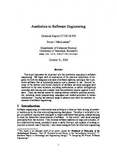
3. The need for semantics In the early days of tabular expressions, informal semantics were given so that authors and readers would have the same understanding of what the tables meant. It is interesting to note that these early, informal semantics were written in terms of the contents of the tables. For example, given the table in Figure 1
Result Condition
f_name
Condition 1
res 1
Condition 2
res 2
... ... ...
...
Condition n
res n
Figure 1 - Simple function table we could say that the table is equivalent to if Condition 1 then f_name = res 1 elseif Condition 2 then f_name = res 2 elseif … elseif Condition n then f_name = res n we would also require that Condition i ∧ Condition j ⇔ FALSE ∀i,j=1,..,n i ≠ j and Condition 1 ∨ Condition 2 ∨ … ∨ Condition n ⇔ TRUE
(disjointness) (completeness)
We will see that the above informal semantics looks nothing like the semantics that have been developed for general tabular expressions over the past decade. In fact, most formal semantics of tabular expressions do not include the disjointness and completeness requirements. These requirements come about because in practice we typically need the tables to describe functions in an unambiguous way. The formal semantics of tables is usually concerned (first and sometimes exclusively) with the structure of the table, not the contents. The most important reason for developing semantics is to ensure that authors and readers of the tables have the same unambiguous understanding of the meaning of the tables. In simple cases such as for the table above, the semantics in terms of the if … elseif structure may suffice. However, as soon as the tables get more complex, or we need the semantics for different reasons as discussed below, those rudimentary semantics are no longer useful. If tabular expressions are to be truly useful in software practice, they will have to be supported by software tools. So, another high priority reason for creating general semantics for tables, is to enable us to develop software tools for creating, editing and transforming tables. Tabular expression semantics are useful/necessary in other situations as well. For instance, tables and sub-tables are an indispensable notation device in partitioning the behaviour in a requirements document. It is also often useful to link tables of different types. In both cases, without semantics we are not sure if the composition of the tables is unambiguously defined. As an example, let us look at the combination of a state transition table and a typical function table. The tables are modified/simplified versions of tables used in a requirements document for SDS1 at Darlington. The state transition table is shown in Figure 2.
3/16
Start
NOT [Timeout]
Receive Idle
Receive State Wait for Msg
Wait for Rest
Process Msg
Init
Receive Idle {1} see 2.4
-
-
-
-
Link On
-
Wait for Msg {2} see 2.4
-
-
-
Link Off
-
-
-
-
Part Msg
-
-
Receive Idle {1} see 2.4 Process Msg {3} see 2.4 Wait for Msg {2} see 2.4
Receive Idle {1} see 2.4
Msg Rcvd
Receive Idle {1} see 2.4 Process Msg {3} see 2.4 Wait for Rest {2} see 2.4
Processed & NOT [Link Off]
-
-
-
-
Wait for Msg {2} see 2.4
-
-
Wait for Msg {2} see 2.4
Wait for Msg {2} see 2.4
-
Timeout
-
-
Figure 2 - State Transition Table with links to a Function Table In the above table, - indicates no action, and the events Link On and Link Off are defined by Link On Link Off
= =
Enable requested & NOT PRIOR (Enable requested) NOT (Enable requested) & PRIOR (Enable requested)
Other events are defined by references to other functions. The state transition table above, shows the new state in each cell, and also shows the output on entering that new state by a tag inside curly brackets as well as a reference to a function table. The function table 2.4 is shown in Figure 3. Result
M_CPPF M_Type f_Feedbk M_Gain M_NOP
Condition
{3}
Enable requested & M_Comm exists
Good header
see 2.5
see 2.6
see 2.6
see 2.9
see 2.10
NOT [ Good header ]
DNE
DNE
e_Invalid
DNE
DNE
DNE
DNE
e_Undef
DNE
DNE
DNE
DNE
e_Invalid
DNE
DNE
DNE
DNE
e_2pass
DNE
DNE
DNE
DNE
e_Undef
DNE
DNE
NOT [non-fatal error ] Enable requested & & NOT [ M_Comm NOT [not in 2 passes ] exists ] {2} non-fatal error NOT [non-fatal error ] & not in 2 passes {1}
NOT [ Enable requested ]
Figure 3 - Function Table referenced by a State Transition Table 4/16
In the above table, DNE means Does Not Exist. In earlier versions of these tables the tags in curly brackets were not included. Readers were therefore told to look at function table 2.4 to determine the required behaviour on entering a particular state, without being told exactly where in the table to continue reading. Readers who understood the behaviour on which the events were based for instance, had no difficulty in determining exactly where to look in function table 2.4. However, readers without that knowledge had some difficulty in understanding the required behaviour. For example, the only obvious link between the events in the state transition table and predicates in function table 2.4 is the one between “Link Off” and “NOT [ Enable requested ]” represented by {1}. Even “Link On” presents a problem since it could apply to either {2} or {3} if we look only at its connection with “Enable requested”. To help alleviate this problem, we added the tags in curly brackets. Now the links to particular rows in 2.4 are explicit. The tags also raise some questions. In general, do we want to reference just specific rows or columns in a table? How does a software tool interpret these tags? What implications are there for the verification process in cases like this? Do we have an unambiguous description of behaviour when we link different kinds of tables in this way? Does it make sense to say “see 2.4” in the cells in the state transition table? For that matter, does it make sense to reference sub-tables in this way even if the table and sub-tables are of the same type (as in function table 2.4 itself)? Without semantics these questions are sometimes surprisingly difficult to answer. The problem seems to be that any one person may think the answers are obvious – unfortunately, they seem obvious but still differ from person to person. For many years we have worked on making tabular expressions easier to read and comprehend so that they will be used in industry. One of our ideas was to create what we called natural language expressions (NLEs), that we will discuss in some detail in section 5.1. These NLEs are natural language phrases that have specific meaning to domain experts. For example, we may have an NLE “Low power setpoint is requested or cancelled” and when it is used in a table, we use “Low power setpoint is requested” or “Low power setpoint is cancelled”. So NLEs look a little different from normal mathematical functions. They typically use “is” and “are” as assignment operators, and the range of the NLE is included explicitly in the NLE, separated by “or”. Again, it is important that readers have an unambiguous understanding of NLEs (they are also defined using function tables), and we must be able to build software tools that allow us to parse and use these expressions.
4. Semantics of tabular expressions 4.1. Semantics As discussed in section 2, semantics for tabular expressions have been developed by a number of people over the past twenty years. There are sometimes significant differences between the different approaches. The semantics we will use are those developed in [14]. To illustrate the principles behind the semantics we will show various stages in their development in the context of a normal table.
x≥0 x 10
y < 10
0 x
y2 x+y
-y2 x-y
Figure 4 - Stage 0. A normal table
5/16
We need to be able to describe the tabular expression structure. To this end, we can decompose tables into headers (H1, H2, …, Hn) and a single grid (G).
H1 H2
y = 10
y > 10
y < 10
x≥0 x