- - White Paper (31Jul02) - -
Target Detection and Recognition in Ground Battlespaces Carl G. Looney Computer Science & Enginering University of Nevada, Reno Reno, NV 9057 U.S.A.
[email protected]
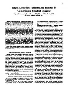
1. Introduction Signals, Images and Targets. Commanders in the U.S. Army need more complete and accurate knowledge of the battlespace with which to make optimal allocation of resources. Advances in sensor and signal technology provide images from SAR, HRR radar, IR, optic (including hyperspectral), and ladar devices. However, many problems remain in the extraction of adequate information from such images. The main targets of interest are ground vehicles that may consist of hundreds of pixels to a subpixel at ranges from less than 1 km to hundreds of kilometers taken from UGV, Commanche, UAV, aircraft, or satellite platforms. Detection and Recognition. Two distinct steps to extracting information are: i) the detection of blobs, or regions-of-interest (ROI’s), that may be targets; and ii) the recognition, or classification of the ROI’s as targets (trucks, tanks, transporter-elevator-launchers, etc.) or non-targets. Recognition is difficult because of the wide ranges of depression angles and aspect angles possible; the various extraneous equipment carried by, or attached onto, the vehicles; a wide variety of kinds and types of vehicles; camouflage; partial occlusion; and a low signal-to-noise ratio in the received signal energy. Fusion of Multiple Images. Detection and recognition may be done on single images, multiple images from different sources or a sequence of images from the same source. To achieve higher accuracy, more than a single image can be used, which leads to other problems: i) the images must be registered so that the same pixel indices in each image refer to the same point in the scene; ii) the images must then be fused to yield a better single image in which the targets are more extractable; and iii) the processing and analysis algorithms must be fast, either aboard the platform or at a central station to which the raw data is transmitted. Current Algorithmic Needs. The tasks of detection, enhancement, registration, fusion and recognition need faster and better algorithms for situation awareness so commanders can operate inside of the enemy decision cycle time [13]. Figure 1 shows our overall approach.
2. Regions of Interest Speckle Removal. For SAR images, and possibly some others, we first remove the speckle noise. If any pixel is sufficiently different from its 6 non-maximal and non-minimal neighbors, then we replace it by the average of the 6 values [11] (a form of selective smoothing). We then apply a dual level histogram equalization that applies separate equalization [4] on the pixels on each side of the 50th percentile value to produce a more uniform distribution in the middle region of the histogram that better equalizes the contrast. A Statistical Approach. By working with the original or its negative, we can assume that the ROI’s are patches of pixels with lighter average intensity than the background. Because of the variation in background intensity across the image, we use a type of adaptive threshold. We use blocks to contain the ROI blobs that are twice the size of the largest target on each of the x and y axes, and the blocks overlap halfway on one or both of the
x and y axes. The variance is a difference measure independent of changing average intensities and so the blocks with larger variances become the ROI blocks. Segmentation Approaches. A second method finds ROI’s by the total spatial frequency criterion given in the next section where target blocks have higher total spatial frequency values [5]. We also investigate a third approach that uses our robust fuzzy clustering algorithm [15, 16] to cluster the image into segments by intensity level. These clusters are independent of location and have disjoint pieces, of which the lightest ones are ROI’s. A (2P)x(2P) block is centered on each such piece, where the maximum target size is PxP. The block is saved for further processing, registration and recognition. A fourth method filters noise via the discrete cosine transform (DCT), identifies the target gray levels in the histogram and eliminates all non-target gray levels [2].
3. Enlargement and Enhancement of ROI’s Enlargement of ROI’s. We now double a block in each of x and y using our special fuzzy interpolation [10, 12] (better than bilinear and faster than bi-cubic). Interpolation smooths the block slightly so the enlarged image is now ready for sharpening. Figure 1. The project process flow. Enhancement of ROI’s. We next apply image enhancement to each ROI block with a 3x3 or 5x5 unsharp masking convolution mask to sharpens without amplifying the noise (unlike derivative based methods such as Laplacians). We will also use our Bessinc (Bessel sinc) function convolution mask [9] that refocuses scattered and diffracted light captured through a circular lens and yields strongly sharpened details without noise gain. We may then apply our fast fuzzy edge detection method [7] and superimpose the lines on the previously enhanced block.
4. Registration Geometric Registration. Of the three types of registration [1], we are concerned here with the geometrical type. The general affine transformation may not always be sufficient, so we develop an extended spatial frequency method and then use the usual polynomial transformation with fairly low degree so as to avoid undulations due to too many maxima and minima [1]. Extended Spatial Frequencies. Given two corresponding enlarged blocks from two images of an ROI, it is necessary to register them. We use a new technique that we call the pointwise spatial frequency (psf) at each pixel, which is different from but related to the spatial frequency used by [5, 6]. We compute these values on a 7x7 nbhd of each interior pixel in a block. At pixel value f(m,n) for image location (m,n) we compute the respective pointwise row, column, left-diagonal, right-diagonal and total spatial frequencies by the following equations for a 7x7 nbhd.
-2-
r(m,n) = (1/7)ÿk=-3,3 |f(m,n) - f(m,n+k)|
(row)
(1)
c(m,n) = (1/7)ÿk=-3,3 |f(m,n) - f(m+k,n)|
(column)
(2)
ld(m,n) = (1/7)ÿk=-3,3 |f(m,n) - f(m+k,n+k)|
(left-diagonal)
(3)
rd(m,n) = (1/7)ÿk=-3,3 |f(m,n) - f(m+k,n-k)|
(right-diagonal)
(4)
t(m,n) = {r(m,n)2 + c(m,n)2 + ld(m,n)2 + rd(m,n)2}1/2
(total)
(5)
ROI’s that contain targets will have pixel blobs with higher total psf due to both target edges and intensity changes. Now we look for four points in each of the associated two blocks, near the top-left, top-right, bottomleft and bottom-right of the corresponding ROI’s. Such correspondence is done by matching their psf feature vectors over 3x3 nbhds of each location (m,n), where the feature vectors are v(m,n) = (r(m,n), c(m,n), ld(m,n), rd(m,n))
(6)
The Polynomial Image Transformation. We transform one block to fit the other one by mapping all points (m,n) in one block to points (m~,n~) in an output block via m~ = a1m + b1n + c1mn + d1,
n~ = a2m + b2n + c2mn + d2
(7)
There are two equations for each pair of points, which makes 8 equations in the 8 unknowns a1, b1, c1, d1, a2, b2, c2, d2 (consider p = mn to be a third variable so that there are 8 linear equations in 8 unknowns) [1, 3, p. 272]. We can add more terms in the polynomial and use more points, but this should not be necessary because of the local registration of ROI blocks rather than global registration of entire images. This should be faster than spectral methods (see [1] for FFT methods).
5. Image Fusion The Fusion Approach. We now fuse the two corresponding enlarged and registered blocks via a simple but powerful process. Fusion is done at each pixel with the 7x7 nbhd total psf at each pixel. We consider each pair of corresponding pixels and select the pixel value with the greatest total pointwise spatial frequency to be the fused output pixel value. It is shown in [5] that the spatial frequency at a point is greater for higher clarity at that pixel. The resulting output block will contain the best pixel values from each of the two blocks. It is clear that this process can be done with K > 2 corresponding blocks from K images. The fusion is done only on corresponding blocks rather than on entire images.
6. The Hyperspectral Application This fusion is ideal for hyperspectral images because the computationally complex registration is not necessary. These are a set of images taken at the same time and place of the same scene, usually in dozens of different bands. Each wavelength band shows the scene differently because of the interaction with the reflecting surfaces in the scene. A few bands can be selected for their relevance in showing desirable details. The particular bands will be influenced by the aspect and depression angles and the lighting. This is an important area for theoretical analysis as well as practical experimentation to catalog such bands versus conditions and backgrounds. We
-3-
fuse blocks in the selected K bands to obtain the output pixel value at each block location (m,n), where fk(m,n) is the pixel value at (m,n) of the kth image block and sk(m,n) is the pointwise total psf at (m,n). fout(m,n) = fk*(m,n), sk*(m,n) = maxk=1,K {sk(m,n)}
(8)
7. Target Recognition From the resulting single fused image, we perform automatic target recognition (ATR). While humans in the loop are better at this so far, algorithms are needed that can do this quickly and accurately both as an aid to humans and as a human replacement. Our approach uses our fuzzy classifier [17]. We first cluster the psf vectors of the exemplar ROI block that contains a target and obtain the prototype vectors. By circular rotation of these vector components we obtain 45° rotations of the targets in the (x,y)-plane, which lowers significantly the number of cases to be stored. Given an output block of standardized size, standardized target cases are retrieved that are the best matches to all of its circular rotations, and interpolations may be made to get the best match. Another promising method is to perform the discrete wavelet transform (DWT) using Haar functions for speed. The DWT coefficients for a blob are computed and the closest ones are retrieved from a base of target coefficients. This method is invariant in spatial size of the blob, but requires a large number of stored cases. An advantage is that the coefficients will match even if the poses differ a small amount, i.e., the aspect and depression angles differ by a several degrees. An third approach is to aid human perception of targets by enhancing of the ROI blobs to provide a relief against the background by a pseudo side lighting effect on the direction from which the image is captured [10]. We will also investigate the use of exemplary data to train our powerful radial basis functional link net [14] that is more powerful than the radial basis function neural network and is also easy to train. Our new version of this network uses ellipsoidal basis functions that are fit to the particular exemplary class data (see [8] for the original that was called an RVFLN). ATR was done with resilient backpropagation in [18].
References [1] Lisa G. Brown, “A survey of image registration techniques,” ACM Computing Surveys 24(4), 325-376, 1992. [2] B. Carlson and C. Looney, “Dual target cleaning for detection in clutter,” Proc. 14th Int. Conf. on Computer Applications in Industry and Engineering, Las Vegas, 99-102, 2001. [3] R. C. Gonzalez and R. E. Woods, Digital Image Processing, 2nd Edition, Prentice-Hall, Upper Saddle River, NJ, 2001. [4] Y. T. Kim, “Quantized bi-histogram equalizaton,” IEEE Trans. Acoustics, Speech and Signal Processing, Vol. 4, 2797-2800, 1997. [5] S. Li, J. T. Kwok and Y. Wang, “Combination of images with diverse focuses using the spatial frequency,” Information Fusion 2, 169-176, 2001. [6] S. Li, J. T. Kwok and Y. Wang, “Multifocus image fusion using artificial neural networks,” Pattern Recognition Letters 23, 985-997, 2002. [7] Lily R. Liang and Carl G. Looney, Fuzzy competitive edge detection, (in press), 2002. Reno, 2002. [8] C. G. Looney, Pattern Recognition Using Neural Networks, Oxford University Press, NY, 1997.
-4-
[9] C. G. Looney, “Refocusing blurred images,” Proc. ISCA 11th Conf. on Computer Applications in Industry and Engineering, Las Vegas, 223-227, 1998. [10] C. G. Looney, “Fuzzy interpolation and pseudo side lighting image processing,” Proc. ISCA Int. Conf. on Intelligent Systems, Melun, France, 208-211, 1998. [11] C. G. Looney, “Nonlinear rule-based convolution for refocusing,” Real-Time Imaging 6, 29-37, 2000. [12] C. G. Looney, “Fuzzy and rule-based image convolution,” Math. & Computers in Simulation 51, 209219, 2000. [13] C.G. Looney, “Exploring fusion architecture for a common operational picture,” Information Fusion 2, 251-260, 2001. [14] C. G. Looney, “Radial basis functional link nets and fuzzy reasoning,” Neurocomputing, 48 (1-4), 489509, 2002. [15] C. G. Looney, “Interactive clustering and merging with a new fuzzy expected value,” Pattern Recognition 35 (11), 187-197, 2002. [16] C. G. Looney, “Pattern Recognition,” in Optic Mechatronic Systems, Ed. H. Cho., CRC Press, Boca Raton, FL, 2002. [17] C. G. Looney, A fuzzy classifier network with ellipsoidal Epanechnikov functions, Tech. Report, Computer Science & Engineering, University of Nevada, Reno, 2002. [18] L. M. Patnaik and K. Rajan, “Target detection through image processing and resilient propagation algorithms,” Neurocomputing 35, 123-135, 2000.
6. Proposed Cost and Duration The proposed duration is 3-years, starting in May 2003 and ending in May 2006 (Total of $391,536). Year 1 (Years 2 and 3 are the same): PI 2 mos., full time Summer $ 18,000 Consultant 6 mos., 1/2 time $ 30,000 3 Research Ass’ts 9 mos., ½ time, $1200/mo., times 3 $ 32,400 3 Research Ass’ts 2 mos. full time, Summer, $2400/mo., times 3 $ 14,400 Travel, Publication, Misc. $ 5,000 Indirect Costs 44% of ($125,000 - $30,000 [consultant]) $ 30,712 ________________________________________________________________________________ Total for Year 1 $130,512
7. Addendum: Biosketches of Principle Investigator and Consultant Principle Investigator: Professor Carl G. Looney, Computer Science & Engineering Dept., University of Nevada, Reno; Ph.D. University of Iowa, Mathematics; BS, MS, University of Nevada, Reno. Dr. Looney has worked at Hughes Ground Systems in Southern California (1980-1984) both as a systems analyst employee and later as a consultant (error analysis of the Egyptian air defense system, Japanese air defense system design); Logicon at Vandenburg AFB, CA (tracking the Peacekeeper ICBM); Kentron Int’l (tracking cruise missiles at Hill AFB, Utah); Veda, Inc. (avionics error analysis, operational flight program for the F4-E German fighter aircraft); and as a mathematics professor at the University of Toledo (taught advanced engineering mathematics, numerical analysis. Dr. Looney initiated fuzzy Petri nets for reasoning, advanced pattern recognition with a fundamental paper on a new fuzzy clustering algorithm, invented a fuzzy classifier that uses ellipsoidal extended Epanechnikov functions as fuzzy set membership functions and trains itself on exemplar data with no weights.
-5-
Additionally, he and a research assistant invented a new fuzzy edge detector that is much faster than the Canny method and makes excellent edges. He also invented the ellipsoidal basis functional link net (not yet submitted) and developed an algorithm that both smooths and sharpens an image. He wrote two articles in the CRC Handbook of EE (ed. R. Dorf, 1995) and has recently written the chapter on pattern recognition in CRC’s Optic Mechatronic Systems (ed. H. Cho, 2002). Some papers are listed in the references above. Consultant: Dr. William A. Peppin holds a Ph.D. in Geophysics from the University of California at Berkeley. He was recently awarded the M.S. in computer science from the University of Nevada, Reno, for which his thesis culminates 7 years of study in image processing and applications. He was supported by a 2-year grant from the NASA Earth Applications Commercial Applications Program. Dr. Peppin was mentored at Homestake Mining Company in Reno by Dr. Richard Bedell on hyperspectral data (from the JPL AVIRIS imager). Some of his most recent papers are listed below. > Hauff, P.L., Peters, D.C., Borstad, G., Peppin, W.A., Dillenbeck, E., Closs, L.G., and E. C. Prosh, 2000. “Hyperspectral investigations of mine waste and abandoned mine lands – the Dragon calibration site case study,” Proc Ninth JPL Airborne Earth Sci. Workshop, JPL Publication 00-18, 233 – 242. > Hauff, P.L., D.C. Peters, W.A. Peppin, E.C. Prosh, E.D. Dillenbeck, G.A. Borstad, R. Diaz, and D. Robbins, 2000. “The Ray copper mine, Arizona – accuracy assessment of hyperspectral imagery,” Proc. Tenth JPL Airborne Earth Sci. Workshop, JPL, abstract. > Peppin, W.A., P.L. Hauff, D.C. Peters, E.C. Prosh, and G. Borstad, 2000. “Different correction-toreflectance methods and their impacts on mineral classification using SFSI and low- and high-altitude AVIRIS,” Proc. Tenth JPL Airborne Earth Sci. Workshop, JPL, abstract. > Peppin, W.A., Hauff, P.L. and D.C. Peters, 2000. “Classification over Dragon Mine, Utah from AVIRIS/SFSI versus ground observations,” ERIM Fourteenth Geologic Conference, Las Vegas, Nevada. > Peppin, W.A., 2001. “Fast Image Retrieval Using Truncated Wavelet Expansion,” Univ. of Nevada, Reno, CS 791 class project. > Peppin, W.A., 2001. “Expert-Guided Fuzzy/Holistic Hyperspectral Image Classification,” Masters Thesis in Computer Science, University of Nevada, Reno. > Peppin, W.A. and Looney, C.G., 2001. “Fuzzy Classification Applied to Hyperspectral Imagery (AVIRIS) Over the Dragon Mine, Utah,” Int. Soc. Computers and Their Applications, Proceedings, Las Vegas, Nevada. > Peppin, W.A., Looney, C.G. and P.L. Hauff, 2002. “Image classification using a method which combines an holistic approach with fuzzy feature extraction,” Proc Ninth JPL Airborne Earth Sci. Workshop.
-6-