Email: {sgogineni,nehorai}@ese.wustl.edu ... the target from different angles (see Fig. 1). Hence ... we show that we can accurately estimate the target properties.
Target Estimation Using Compressive Sensing for Distributed MIMO Radar� Sandeep Gogineni, Student Member, IEEE and Arye Nehorai∗ , Fellow, IEEE Department of Electrical and Systems Engineering Washington University in St. Louis One Brookings Drive, St. Louis, MO 63130, USA Email: {sgogineni,nehorai}@ese.wustl.edu Phone: 314-935-7520 Fax: 314-935-7500
Abstract—Distributed Multiple Input Multiple Output (MIMO) radar systems enable viewing the targets from different angles, thereby providing spatial diversity gain. In this paper, we propose an approach to accurately estimate the parameters (position, velocity) of multiple targets using such systems from fewer number of samples by employing compressive sensing. We also introduce a new metric to analyze the performance of the radar system. We show the improvement in performance over conventional Single Input Single Output (SISO) radar systems due to the spatial diversity offered by MIMO radar. We also demonstrate that the sampling rates can be significantly reduced by using compressive sensing at the receivers. Index Terms—Multiple Input Multiple Output (MIMO) radar, distributed, widely separated antennas, compressive sensing, multiple targets
dĂƌŐĞƚƐ
�ŶƚĞŶŶĂƐ
I. I NTRODUCTION Multiple Input Multiple Output (MIMO) radar with distributed antennas [1]–[6] has attracted a lot of attention recently due to the improvement in performance it offers over conventional single antenna systems. In distributed MIMO radar, the antennas are widely separated. This enables viewing the target from different angles (see Fig. 1). Hence, if the target returns between a particular transmitter and receiver are weak, then it is highly probable that they will be compensated by the returns between other antenna pairs. In this paper, we study MIMO radar with widely separated antennas in the context of sparse modeling and compressive sensing for estimating the positions and velocities of multiple targets. Compressive sensing allows us to accurately reconstruct data from significantly fewer samples than the Nyquist rate if the received signal is sparse in some basis representation [7]– [10]. With the improvement in the capabilities of the computational resources, it has become more feasible to use compressive sensing for different medical and engineering applications [11]–[16]. Since the number of targets in a radar scene is often limited, we can use sparse modeling to represent the radar data. Therefore, compressive sensing is applicable to the field of radar [13]–[16]. So far, compressive sensing has been used for MIMO radar only in the context of closely spaced �This work was supported by the Department of Defense under the Air Force Office of Scientific Research MURI Grant FA9550-05-1-0443, ONR Grant N000140810849, NSF Grants CCF-1014908 and CCF-0963742. ∗Corresponding author
978-1-4244-9721-8/10/$26.00 ©2010 IEEE
793
Fig. 1.
MIMO radar with widely separated antennas.
antennas [15]–[17]. Distributed MIMO radar is important since it provides spatial diversity. In [16], the authors call their system distributed MIMO radar even though they are actually using colocated MIMO radar. This is evident from the fact that they use the same RCS value for all transmitter-receiver pairs. In this paper, we present a sparse modeling framework for MIMO radar with widely separated antennas (see also [18], [19]) and demonstrate that the sampling rates can be significantly reduced by employing compressive sensing. We also introduce a new metric to analyze the performance of the radar system. This paper is organized as follows. In section II, we derive the signal model for MIMO radar with widely separated antennas using sparse representation. In section III, we introduce compressive sensing to reduce the sampling rates at the receiver side. In section IV, we deal with the problem of sparse support recovery to infer about the properties of the targets (position, velocity). We present Basis Pursuit (BP) principle for the recovery of the sparse vectors. In section V, we propose a new metric to judge the performance of the
Asilomar 2010
radar system. In section VI, we use numerical results to show the performance of the proposed MIMO radar system. We demonstrate the improvement in performance when compared with conventional single antenna radar systems. Additionally, we show that we can accurately estimate the target properties from very few number of samples by using compressive sensing. In section VII, we conclude this paper. II. S IGNAL M ODEL In this section, we describe the signal model for our MIMO radar system. We assume that there are MT transmitters, MR receivers, and K targets. We assume that the targets are point like with RCS values that vary with the angle of view. Further, we assume that all the targets are moving in a two dimensional plane. However, without loss of generality, we can extend the analysis in this paper to the three dimensional case. The k th − → � � target is located at pk = pkx , pky on a Cartesian coordinate − → � � system and it moves with a velocity v k = vxk , vyk . The ith � → � − transmitter and� j th receiver are located at ti = tix , tiy and � → − rj = rjx , rjy , respectively. We transmit orthonormal waveforms from the different transmitters. Let wi (t) be the complex baseband waveform transmitted from the ith transmitter. Then, the bandpass signal emanating from the ith transmit antenna is given as � � w �i (t) = Re wi (t)ej2πfc t , (1) √ where Re{·} denotes the real part of the argument, j = −1, fc is the carrier frequency. These signals travel in space and reflect off the surfaces of the targets and are captured by the receivers. Further, we assume that the cross correlations between these waveforms is close to zero for different delays [1]–[2]. Define akij (t) as the attenuation of the k th target between the ith transmitter and the j th receiver. Note that these attenuation values are dependent on the transmitterreceiver indices under consideration. This is a result of the wide separation between the antennas. Under a narrow band assumption, the bandpass signal arriving at the j th receiver can be expressed as �K M T ��
yj (t) = Re akij (t)wi t − τijk × k=1 i=1 � �� k j2π fD (t−τijk )+fc (t−τijk ) ij
e
,
where τijk and fDk ij are the delay and Doppler shift corresponding to the k th target.
− → → − → − 1 → τijk = rj � , (2) �pk − ti � + �pk − − c
→ − → − → → − fc − (3) fDk ij = �v k , uk rj � − �v k , uk ti � , c − → − → where uk ti , uk rj denote the unit vector from the ith transmitter to the k th target and the unit vector from the k th target to the j th receiver, respectively; �, � is the inner product operator, and c is the speed of propagation of the wave in the medium.
794
We define the target state vector ζ = [px , py , vx , vy ]T . Hence, the important properties of the target (position, velocity) are specified by ζ. The goal is to estimate ζ for all the K targets. The received signals at each receiver are first down converted from the radio frequency and then passed through a bank of MT matched filters, each of which corresponds to a particular transmitter. Under the orthogonality assumption [1]–[2], the sampled outputs of the ith matched filter at the j th receiver is given as � � � k j2π fD (n−τijk )−fc τijk + e (n), (4) ij yij (n) = akij (n)e ij k∈K
where eij (n) is the additive noise at the output of the ith matched filter of the j th receiver, K represents a set containing all the targets that contribute to the matched filter output at n. In order to arrive at the above expression, we also assume that the target RCS values do not vary within a pulse duration and the Doppler shift is small. In other words, we assume that akij (t)ej2πfDij t varies slowly when compared with wi (t). Now, we discretize�the target state space into a grid of L values � ζ l , ∀l = 1, . . . , L . Hence, each of the targets is associated with a state vector belonging to this grid. If a target at ζ l contributes to the matched filter output at n, then define l ψij (n) = e
� � l j2π fD (n−τijl )−fc τijl ij
.
(5)
l (n) = 0. Also, if ζ l is the state vector of the Otherwise, ψij k th target, we define
slij (n) = akij (n).
(6)
Otherwise, slij (n) = 0. For each j, we stack slij (n), yij (n), and eij (n) corresponding to different transmitters to obtain MT dimensional column vectors slj (n), y j (n) and ej (n), l respectively. Similarly, we arrange ψij (n) into (MT ) × (MT ) l dimensional diagonal matrix Ψj (n). slj (n) =
� l �T s1j (n), . . . , slMT j (n) ,
(8)
T
(9)
y j (n) =
[y1j (n), . . . , yMT j (n)] ,
ej (n) =
[e1j (n), . . . , eMT j (n)] , � l � l diag ψ1j (n), . . . , ψM (n) , Tj
Ψlj (n) =
(7)
T
(10)
where diag{·} refers to a diagonal matrix whose entries are T given by {·} and [·] denotes the transpose of [·]. Further, � l �MR � �MR R we arrange sj (n) j=1 , y j (n) j=1 , and {ej (n)}M j=1 into MT MR dimensional column vectors sl (n), y(n), and e(n), � �MR respectively and Ψlj (n) , into (MT MR ) × (MT MR ) j=1
dimensional diagonal matrix Ψl (n). �
T
T �T sl (n) = sl1 (n) , . . . , slMR (n) , � � T
T T y(n) = (y 1 (n)) , . . . , y MR (n) , �T � T T , e(n) = (e1 (n)) , . . . , (eMR (n)) � � Ψl (n) = diag Ψl1 (n), . . . , ΨlMR (n) .
(11) (12) (13) (14)
� �L � �L Finally, stacking sl (n) l=1 and Ψl (n) into LMT MR l=1 dimensional column vector and (MT MR ) × (LMT MR ) dimensional matrix, respectively, we obtain � �T s(n) = s1 (n), . . . , sL (n) , (15) � � 1 L Ψ(n) = Ψ (n), . . . , Ψ (n) . (16) Therefore, we can express the received vector at the nth snapshot as y(n) = Ψ(n)s(n) + e(n), (17) where s(n) is a sparse vector with KMT MR non-zero entries. We have expressed our observed data using sparse representation. We assume that the target RCS values do not vary over a N period of N snapshots. Now, we stack {y(n)}N n=1 , {e(n)}n=1 , N and {Ψ(n)}n=1 into � �T T T y = (y(1)) , . . . , (y(N )) , (18) �T � T T , (19) e = (e(1)) , . . . , (e(N )) �T � T T Ψ = (Ψ(1)) , . . . , (Ψ(N )) , (20) to obtain y (N MT MR )×(1)
=
Ψ(N MT MR )×(LMT MR ) s(LMT MR )×(1) +e(N MT MR )×(1) .
Note that in the above expression for the measurement vector, Ψ is known and only s depends on the actuals targets present in the illuminated area. III. C OMPRESSIVE S ENSING Compressive sensing allows us to accurately reconstruct data from significantly fewer samples than the Nyquist rate if the received signal is sparse [7]. Nyquist rate sampling assumes the signals to be bandlimited. Similarly, the requirement for applying compressive sampling is that the signals must have a sparse representation using some basis. In section II, we saw that the measurement vector y has dimensions N MT MR . Since our measurement vector is sparse in the space spanned by the columns of the matrix Ψ, the theory of compressive sensing says that we can reconstruct the vector s from far fewer samples than contained in the vector y. If the sensing basis is represented by Φ, then the coherence measure between Φ and Ψ measures the largest correlation between them. Φ must be such that it has as little coherence with Ψ as possible [7]. Since random matrices satisfy low coherence properties, we generate the entries of the (NCS )× (N MT MR ) dimensional sensing matrix Φ from Gaussian distribution, where NCS � N MT MR . The new measurement vector in the presence of noise is y CS = ΦΨs + Φe.
(21)
For reconstruction of s, we use basis pursuit approach that is NCS × 100% as the mentioned in the next section. Define N M T MR percentage of samples used in compressive sensing. In section VI, we will show the performance of the MIMO radar system for different levels of compression.
795
IV. S PARSE S UPPORT R ECOVERY In section II, we have expressed the signal received across MR receive antennas over N snapshots using sparse representation. In order to find the properties of the targets (position, velocity), we need to recover the sparse vector s from the measurements y CS . We shall use Basis Pursuit (BP) for sparse support recovery in the numerical simulations to demonstrate the performance of the MIMO radar system. In BP, we minimize an objective function [20] and we are guaranteed to solve the optimization problem. BP is presented under two scenarios; in the absence of noise and in the presence of noise. 1) Absence of Noise: In the absence of noise, BP aims at minimizing �s�1 under the constraint y CS = ΦΨs. Define Θ = ΦΨ. There are many different vectors s that satisfy the constraint. We choose the solution that has the least l1 norm. This optimization problem can be modeled as a linear program [20]. There are many existing algorithms to solve this problem. One such algorithm is the BP-Simplex algorithm. We (0) begin with a basis set ΘB that contains KMT MR linearly independent columns of Θ such that y CS lies in the column (0) (0) space of ΘB . The rest of the columns form another set ΘB . (0) (0) We recover the initial estimate s by using the basis ΘB . � In every subsequent iteration k ≥ 1, we choose the swap (k� −1) (k� −1) of a column between ΘB and ΘB such that the l1 � norm of the reconstructed vector s(k ) corresponding to this swap is lower than that corresponding to any other swap. We update the basis sets according to this swap. Once we reach the optimal solution, there will be no swap that will further reduce the l1 norm. This algorithm always guarantees convergence to the optimal solution in the absence of noise. 2) Presence of Noise: Clearly the above approach of basis pursuit will fail in the presence of noise. Hence, in [20], the authors propose Basis Pursuit De-Noising (BPDN). This is an unconstrained minimization problem 1 2 (22) min �y CS − Θs�2 + λ�s�1 . 2 � Typically λ = σ 2 log (LMT MR ) where σ represents the noise level. To solve this problem we used CVX, a package for specifying and solving convex programs [21], [22]. We present the results in section VI. V. P ERFORMANCE M ETRIC We define a useful performance metric to analyze the performance of the proposed radar system. As mentioned earlier, the LMT MR length vector s has only KMT MR nonˆ. zero entries. Let the reconstructed vector be denoted by s We would like to have the most significant KMT MR entries ˆ correspond to the same indices as the non-zero entries of s of the actual sparse vector s. If this is not the case, then we will wrongly map the target states for one or more targets. We define an L length vector ˜(l) = s
MR MT � �
2
�ˆ s(MT MR (l − 1) + MR (j − 1) + i)� ,
i=1 j=1
∀l = 1, . . . , L.
Define s˜∗ as a K length vector which contains the values that ˜ carries at the correct K indices. Similarly we define s˜∗ as s a L length vector that takes a value of 0 at the correct K ˜ at every other index. indices and takes the same values as s It is clear that the non-zero entries of s˜∗ correspond to the non-target states and the zero entries correspond to the correct target states. We define the metric min s˜∗ . (23)
= max s˜∗ If this metric has a value greater than one, then all the actual (correct) target indices dominate the other indices in ˜. Otherwise, the estimates are not good enough. Hence, the s higher the value of , the better the performance of the system. In section VI, we use this metric to analyze the results. VI. N UMERICAL R ESULTS We begin with a description of the simulated scenario. We simulated a 2×2 MIMO radar system. We denote the positions of all the transmitters, targets and receivers on a common Cartesian coordinate system. The transmitters are located at → − → − t1 = [100, 0] m and t2 = [200, 0] m, respectively. The → − → receiver locations are r1 = [0, 200] m and − r2 = [0, 100] m, respectively. The carrier frequency of the transmitted waveforms is fc = 1GHz. Within each processing interval, we consider three pulses that are transmitted 33.3ms apart. We choose N = 243 for the simulation results. Therefore, y has 972 entries. We divide the target position space into 9 × 9 grid points and the target velocity space into 5 × 5 grid points. Therefore, the total number of possible target states L = 2025. We considered the presence of 3 targets. Hence, the 8100 dimensional sparse vector s has only KMT MR = 12 nonzero entries corresponding to the targets. The positions and the velocities of the targets are given as − → p1 = [110, 280] m, − → v 1 = [120, 100] m/s, − → p2 = [80, 280] m, − → v 2 = [110, 110] m/s, − → p3 = [100, 260] m, − → v 3 = [130, 130] m/s. The attenuations corresponding to the 3 targets are � 1 1 1 1 � a , a12 , a21 , a22 = [0.3�, 0.3�, 0.7�, 0.8�] , � � 11 a211 , a212 , a221 , a222 = [0.4�, 0.5�, 0.3�, 0.2�] , � 3 3 3 3 � a11 , a12 , a21 , a22 = [0.4�, 0.5�, 0.8�, 0.7�] , √ where � = 1 + −1. The entries of e are generated independently from Gaussian distribution. We assume each of these samples has the same variance σ 2 . We define the signal to noise ratio (SNR) for the MIMO radar system as ⎛ ⎞ 2 �Ψs� � ⎠ dB. SNR = 10 log ⎝ � (24) E �e�2
796
We used 25 independent Monte Carlo runs to produce the simulation results.
3 2.5 2 1.5 1 0.5 0 140 120
320 300
100
280
80
260 60
px (in m)
240
py (in m)
2.5 2 1.5 1 0.5 0 130 120
130 120
110
110
100 vx (in m/s)
100 90
90
vy (in m/s)
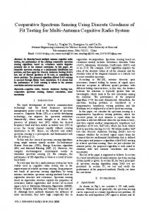
Fig. 2. Reconstructed vectors using basis pursuit de-noising at SNR=23.2dB using 14.8% of the samples, (a) position estimates, (b) velocity estimates.
First, we plot the reconstructed vector when only 14.8% of the samples are used. We performed these simulations at an SNR of 23.2dB. Since it is not possible to plot the position and velocity on the same plot, we plotted the estimates of position and velocity separately. For computing the estimate at a particular grid point on the position plot, we average over all 5 × 5 velocity grid points corresponding to that position grid point. Similarly, we average over all the 9 × 9 position grid points in order to obtain the velocity plot. We do this only to be able to plot position and velocity estimates separately. We can see from Fig. 2 that the target parameters have been correctly reconstructed. Next, we shall plot the performance of MIMO radar for different percentages of samples used. As we defined earlier, the percentage of samples used is given by NCS × 100%. (25) N MT MR We can clearly see from Fig. 3 that by using just 14.8% of the samples, we can obtain > 1 for SNR as low as 10dB. We also observe that as the percentage of samples increases, the performance of the MIMO radar system also improves.
systems. We used numerical simulations to demonstrate the improvement offered by such systems over conventional SISO radar systems. We showed that even for smaller sampling rates, accurate reconstruction is possible at the receiver when we use compressive sensing.
9 8 14.8% Samples 10.3% Samples 7.4% Samples
7 6
R EFERENCES
4
[1] A. M. Haimovich, R. S. Blum, and L. J. Cimini, “MIMO radar with widely separated antennas,” IEEE Signal Process. Mag., vol. 25, pp. 116–129, Jan. 2008. [2] S. Gogineni and A. Nehorai, “Polarimetric MIMO radar with distributed antennas for target detection,” IEEE Trans. Signal Process., vol. 58, pp. 1689–1697, Mar. 2010. [3] M. Akcakaya, M. Hurtado, and A. Nehorai, “MIMO radar detection of targets in compound-gaussian clutter,” in Proc. 42nd Asilomar Conf. Signals, Syst. Comput., Pacific Grove, CA, Oct. 2008, pp. 208–212. [4] J. Li and P. Stoica, MIMO radar signal processing. Hoboken, NJ: John Wiley & Sons, Inc., 2009. [5] J. Zhang, B. Manjunath, G. Maalouli, A. Papandreou-Suppappola, and D. Morrell, “Dynamic waveform design for target tracking using MIMO radar,” in Proc. 42nd Asilomar Conf. Signals, Syst. Comput., Pacific Grove, CA, Oct. 2008, pp. 31–35. [6] S. Gogineni and A. Nehorai, “Polarimetric MIMO radar with distributed antennas for target detection,” in Proc. 43rd Asilomar Conf. Signals, Syst. Comput., Pacific Grove, CA, Nov. 2009, pp. 1144–1148. [7] E. J. Candes and M. B. Wakin, “An introduction to compressive sampling,” IEEE Signal Process. Mag., vol. 25, pp. 21–30, Mar. 2008. [8] D. Donoho, “Compressed sensing,” IEEE Trans. Inf. Theory, vol. 52, pp. 1289–1306, Apr. 2006. [9] E. J. Candes, J. Romberg, and T. Tao, “Robust uncertainty principles: Exact signal reconstruction from highly incomplete frequency information,” IEEE Trans. Inf. Theory, vol. 52, pp. 489–509, Feb. 2006. [10] E. J. Candes and T. Tao, “Near-optimal signal recovery from random projections: Universal encoding strategies?” IEEE Trans. Inf. Theory, vol. 52, pp. 5406–5425, Dec. 2006. [11] J. Trzasko, C. Haider, and A. Manduca, “Practical nonconvex compressive sensing reconstruction of highly-accelerated 3D parallel MR angiograms,” in IEEE International Symposium on Biomedical Imaging: From Nano to Micro, Boston, MA, Jun. 2009, pp. 274–277. [12] R. Chartrand, “Fast algorithms for nonconvex compressive sensing: MRI reconstruction from very few data,” in IEEE International Symposium on Biomedical Imaging: From Nano to Micro, Boston, MA, Jun. 2009, pp. 262–265. [13] R. Baraniuk and P. Steeghs, “Compressive radar imaging,” in IEEE Radar Conference, Boston, MA, Apr. 2007, pp. 128–133. [14] M. Herman and T. Strohmer, “Compressed sensing radar,” in IEEE Radar Conference, Rome, May 2008, pp. 1–6. [15] C.-Y. Chen and P. P. Vaidyanathan, “Compressed sensing in MIMO radar,” in 42nd Asilomar Conference on Signals, Systems and Computers, Pacific Grove, CA, Oct. 2008, pp. 41–44. [16] Y. Yao, A. P. Petropulu, and H. V. Poor, “Compressive sensing for MIMO radar,” in IEEE International Conference on Acoustics, Speech and Signal Processing, Taipei, Apr. 2009, pp. 3017–3020. [17] Y. Yu, A. P. Petropulu, and H. V. Poor, “MIMO radar using compressive sampling,” IEEE Jour. of Selected Topics in Signal Proc., vol. 4, pp. 146–163, Feb. 2010. [18] S. Gogineni and A. Nehorai, “Adaptive design for distributed MIMO radar using sparse modeling,” in Proc. Int. Waveform Diversity and Design (WDD) Conf., Niagara Falls, Canada, Aug. 2010, pp. 23–27. [19] ——, “Compressive sensing for MIMO radar with widely separated antennas,” IEEE Trans. Signal Process., submitted. [20] S. S. Chen, D. L. Donoho, and M. A. Saunders, “Atomic decomposition by basis pursuit,” SIAM Review, vol. 43, pp. 129–159, Mar. 2001. [21] M. Grant and S. Boyd. (2009, Jun.) CVX: Matlab software for disciplined convex programming (web page and software). [Online]. Available: http://stanford.edu/∼boyd/cvx [22] ——. (2008) Graph implementations for nonsmooth convex programs, recent advances in learning and control (a tribute to M. Vidyasagar), V. Blondel, S. Boyd, and H. Kimura, editors, pages 95-110, lecture notes in control and information sciences, Springer. [Online]. Available: http://stanford.edu/∼boyd/graph dcp.html
Δ
5
3 2 1 0
Fig. 3.
8
10
12
14
16 SNR (in dB)
18
20
22
24
Performance metric � for different percentages of samples.
Finally, we demonstrate the improvement offered by the MIMO system over conventional SISO systems. This improvement is a result of the spatial diversity provided by distributed MIMO radar. We get multiple views of the target in MIMO radar. Fig. 4 compares these two systems when 14.8% of the samples are used. We can observe that MIMO system significantly outperforms SISO system. The value of for the SISO system is much below 1 even for noise levels as low as σ = 0.01. For the SISO system, we considered → − transmitter and receiver to be present at the locations t1 and − → r 1 , respectively. For fairness of comparison, we increased the number of samples per each pulse by a factor of MT MR for the SISO system. 9 8 7 6 MIMO SISO
Δ
5 4 3 2 1 0 0.01
0.015
0.02
0.025
0.03
σ
0.035
0.04
0.045
0.05
0.055
Fig. 4. Performance metric � for MIMO and SISO systems using 14.8% of the samples.
VII. C ONCLUSION In this paper, we used a new approach to accurately estimate the parameters (position, velocity) of multiple targets using distributed MIMO radar system from fewer number of samples by employing compressive sensing. We also introduced a new performance metric to analyze the performance of these
797