Targeting and Localization for Mars Rover Operations. Mark W. Powell, Thomas Crockett, Jason M. Fox, Joseph C. Joswig, Jeffrey S. Norris, Kenneth J. Rabe,.
Targeting and Localization for Mars Rover Operations Mark W. Powell, Thomas Crockett, Jason M. Fox, Joseph C. Joswig, Jeffrey S. Norris, Kenneth J. Rabe, Jet Propulsion Laboratory, Michael McCurdy, NASA Ames Research Center, Guy Pyrzak, San Jose State University Foundation, NASA Ames Research Center, M/S 262-4
Abstract— In this work we discuss how the quality of localization knowledge impacts the remote operation of rovers on the surface of Mars. We look at the techniques of localization estimation used in the Mars Pathfinder and Mars Exploration Rover missions. We examine the motivation behind the modes of targeting for different types of activities, such as navigation, remote science, and in situ science. We discuss the virtues and shortcomings of existing approaches and new improvements in the latest operations tools used to support the Mars Exploration Rover missions and rover technology development tasks at the Jet Propulsion Laboratory. We conclude with future directions we plan to explore in improving the localization knowledge available for operations and more effective targeting of rovers and their instrument payloads.
I. INTRODUCTION
T
HIS document describes recent advances in the state of practice of targeting activities in the operation of Mars rovers. Teleoperation of robotic rovers over a very long distance such as from Earth to Mars where one-way data transfer times vary from 6 to 20 minutes is a challenging problem. Due to this delay, conventional real-time teleoperation techniques are not applicable and instead we employ onboard vehicle autonomy. Control software on the spacecraft can use images from the stereo camera pairs to track landmarks, identify obstacles, and compute a safe traverse path to a location of scientific interest on the surface. However, in order to perform these tasks effectively the vehicle control system must have knowledge of localization (the position and orientation of the vehicle). Several approaches have been used on Mars surface vehicles to make localization estimates. During the Mars Pathfinder mission (MPF) the Sojourner rover used a heading sensor and wheel encoder counts to estimate changes in position and localization [1]. The Mars Exploration Rovers (MER) also uses inertia measurement unit (IMU) and mobility motor encoder information to estimate position and orientation. Further, the Pancam instrument is equipped with Sun filters, and the control software can perform an autonomous Sun-finding activity. When the vehicle control The work described in this paper was carried out at the Jet Propulsion Laboratory, California Institute of Technology and funded by the Mars Technology Program, the JPL Research and Technology Development Program, the Mars Exploration Rover project and the Mars Science Laboratory project.
system can observe the Sun position, it combines that with its knowledge of the expected position of the Sun at a given time of sol (Martian day) to more accurately refine its estimate of vehicle attitude. Visual odometry [2] is a localization technique that has also been proven effective at producing more accurate position and attitude knowledge than previously used methods, although it requires significant additional onboard computing time. Quality of localization knowledge has a direct impact on how rover activities are planned and refined into commands for execution on the vehicle. Stereo image pairs returned from the vehicle are correlated into 3D XYZ maps of the visible local terrain around the spacecraft. These XYZ maps are collections of accurate 3D position data used for pointing science instruments at very specific points of interest, or targets. However, as the rover traverses on the surface and accumulates error in localization knowledge, these targets become less and less relevant. It is therefore necessary to plan activities that refer to any specific targets prior to any driving activity. The only exceptions to this rule are when a specific target is not visible to a particular instrument from the vehicle’s current position, requiring a drive to bring the target into the field of view of that instrument. In this case, there are two mitigating strategies available: either articulating the instrument in a rastering fashion to increase its effective field of view to compensate for localization error, or acquiring new stereo imagery from the new position, sending it back to Earth and waiting until the next planning cycle (the next sol) to command the science accurately. Both of these strategies have a cost in onboard execution time and bandwidth, and so great care must be taken in operational planning to avoid this cost whenever possible. In the next section we discuss how spacecraft activities are targeted differently depending on their aims. We also describe how a large group of collaborating scientists who are geographically distributed can effectively define targets for operations planning. We then discuss recent improvements we have made in the operational processing of defining and using targets. Finally, we conclude with a discussion of promising future directions in localization and targeting. II. TARGETING ROVER ACTIVITIES A. Coordinate Frame Types The conventions for coordinate frame descriptions that capture the history of rover positions on the surface come in
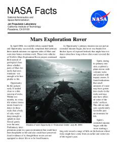
several types. The frame that describes the rover-centric view of the world is called Rover frame. Rover frame is defined as X-forward, Y-starboard, Z-down with an origin defined at a fixed position on the rover body, according to the SAE J670E standard for vehicle coordinate frame. Although not required, it is advantageous to choose an origin point on a holonomic vehicle (a vehicle that is turn-in-place capable) such that the origin point remains fixed in space as the vehicle turns in place. A related frame to Rover frame is Local Level frame, which shares the same origin as Rover frame, but rotates the axes to an orientation of X-north, Y-east, Z-nadir. This rotation is approximated by the estimated pitch, roll, and yaw of the vehicle, and as such it is subject to error in attitude estimation. Accurate vehicle position estimation after a traverse is well-known as a challenging problem, and because of this a third frame convention was defined for surface operations to compensate for the problem. In the absence of localization error, the naïve approach of defining a single world reference frame on the surface of the planet and referencing all subsequent locations on the surface to that frame would be reasonable. In practice where this error does exist, this is not a viable approach. To wit, for a relatively distant target—one which represents a medium-to-long term goal for navigation—the originally specified XYZ coordinate of the target becomes increasingly inaccurate the more the vehicle traverses on the surface and accumulates more and more localization error. It is therefore regularly necessary disregard the history of all vehicle position information to date and define a new “world frame”, called Site frame. This Site frame then becomes the surface-relative (as opposed to rover-relative) frame of reference for all operations planning and targeting. The definition of a Site frame is identical to that of a Local Level frame, and indeed it is correct to say that a Site frame is a particular Local Level frame that is denoted as also being a Site frame. The process for defining which frames are Site frames is managed on the ground. In operations planning, when it is observed that cumulative localization error has risen to the degree that targeting accuracy may suffer, a new Site is defined. Another way to think of a Site is as a local surface region with the vehicle as its center. New Sites may or may not intersect with previous Sites, depending on how much localization error the rover accumulated during a traverse, which itself depends on factors such as wheel slippage on the soil. We can connect all of the Site frames, Local Level frames, and Rover frames from the landing site of the spacecraft all the way to the frame at the most recent vehicle position in a chain. This chain helps to visualize the relationship between the various types of frames that we define that are of operational relevance. Figure 1 illustrates these different types of coordinate frames and their inter-relations. Local level frames are shown in solid black and Rover frames are in dotted red. The black dashed line connects the pre-drive (4,0), mid-drive (4,1), and end-of-drive (4,2) positions. The Local Level frame (4,0) is a Site frame, since its drive index value is
0. As previous discussed, the Local Level frames all share a common orientation of X-north, Y-east, Z-nadir while the Rover frame are relative to the orientation of the vehicle at that position.
N
(4, 0) N
E
W (4, 1) N
S (4, 2) N
Fig. 1. Coordinate frames used to represent the position and attitude of a 6-wheeled rover. Local Level frames (in solid black) are surface-relative and Rover frames (in dotted red) are vehicle relative. The labels above each frame denote its Site and Drive indices, respectively, which uniquely identify each frame. As a labeling mechanism for the history of frames of the spacecraft, the control system maintains a Rover Motion Counter. This counter has several integer index values that increase as the vehicle moves. The Drive index is increased by one every time the vehicle performs a part of a drive, such as a turn-in-place or a single segment of an automated traverse with onboard path planning and obstacle avoidance. There is also a Site index in the counter which is incremented whenever the operations planners need to declare a new Site to mitigate localization error. When the Site index increases by one, the Drive index is reset to zero and then increases with each new drive segment as before. The Rover Motion Counter is a useful tool to correlate the telemetry returned from the vehicle to the position of the vehicle. It is also possible to use image data returned from the spacecraft to refine the localization knowledge of the vehicle during operations planning since the frames and images are correlated by the counter. We will discuss this possibility further in Section III.B.1). B. Navigation Activities Navigating rovers on Mars involves two modes of driving: commanded and semi-autonomous. Commanded driving is used when there are enough images available from the spacecraft to assess the topography of the terrain to determine a safe path by inspection during operations planning. If a rover driver who is operating the spacecraft determines that a particular path is safe to drive, she may choose to command a drive directly by programming a sequence of drive arcs and turns-in-place to drive the vehicle to a new position. This mode of driving is advantageous in that it requires minimal computing time from the vehicle’s onboard controller and power consumption, but has the disadvantage that it can only
be used when an operator has sufficient information to determine a safe path. If the terrain safety cannot be determined by inspection, the rover driver may command a semi-autonomous drive to a waypoint (drive target), which employs onboard path planning, obstacle avoidance, and localization estimation to navigate to the target. For commanded driving, waypoints are generally not used, since the drive commands are simulated on terrain models derived from spacecraft imagery to ensure their safety and effectiveness. Targets are always used for semi-autonomous drives as goal specification for the onboard navigation control system. Since it is often the case that a planning cycle may contain a combination of commanded drives followed by semi-autonomous drives, targets for semi-autonomous drives must be specified in Local Level frame or Site frame. In practice, the Mars Exploration Rovers only retain knowledge of the most recent Site frame, Local Level frame, and Rover frame. Thus, after any drive command is executed, targets that are specified in Rover frame are irrelevant. As a result, drive commands use waypoints designated in Site frame. C. Remote Science Activities Activities that point remote science instruments such as mast-mounted high resolution cameras and spectrometers are targeted in a variety of ways. Many articulated masts used on rovers such as the Mars Exploration Rovers have two degrees of freedom to pan and tilt the head of the mast and thus point the science instruments, so let us assume this is the case for this discussion. For targeting a body of air, such as is done when measuring the amount of dust in the atmosphere, it is often sufficiently accurate to point the mast at a particular azimuth (pan angle) and elevation (tilt angle). This mode of targeting is called pointing in azimuth and elevation or Az/El, which is the simplest method of targeting remote science. Az/El targeting is also used in other commonly used activities, such as acquiring a new set of stereo navigation images after a long traverse into new terrain or very distant features such as hills that lay far out toward the horizon. For remote science surface features that are relatively close to the vehicle, such as within 20 meters for example, XYZ targeting is required for greatest accuracy. Such accuracy is needed to capture a specific, small location such as on a small rock or a specific region of interest such as an interesting segment of crater rim or wall. High target accuracy can also result in greater conservation of communication bandwidth for returning science data to Earth. If targeting is sufficiently accurate, images or sets of images can be subframed or cropped to a fraction of their normal size to return only the region of interest. Subframing is conventionally used to capture images of the calibration target, which is mounted on the rover deck at a precisely known position, and it is also used whenever possible for imaging small targets on the surface to reduce data volume. Because of localization error, image capture operations are planned to execute before driving whenever possible. When targeted imaging is
executed before a drive, it is generally targeted in Rover frame or the current Local Level frame with targets specified in the latest image data returned from the spacecraft at the time. If imaging must occur after a drive, it is targeted in Site frame since as previously noted the knowledge of the Rover frame before the drive is lost but the knowledge of Site frame is retained. D. In-situ Science Activities Targeting in-situ science instrumentation calls for the highest positioning accuracy of all of the types of activities we have discussed. In-situ instruments are mounted on a robotic arm or manipulator, generally at its outermost end or end effector. Depending on the instrument, to obtain science data the manipulator must either place either in contact with or very close to a particular surface. For the in-situ instruments on the Mars Exploration Rover, targeting accuracy of 0.5 cm is required for safe manipulator operation and effective science data acquisition. To achieve this, in-situ activities are conventionally commanded prior to any driving and on targets defined in Rover frame. III. TARGETING PARADIGMS A. Improving Localization in Operations As previously discussed, the onboard control system on the Mars Exploration Rover retains knowledge of only the most recent Rover frame, Local Level frame, and Site frame. This strategy has the benefit of lowering the complexity of the onboard localization and navigation control system. Even in the presence of localization error, activities can be accurately targeted when image data from the vehicle’s current position is available. Operationally, localization error creates a number of challenges. For instance, consider a multi-sol campaign to map a particular section of crater wall that requires a series of drives and image acquisitions. The desired end result is to construct an integrated map of the wall, bringing together image data taken from different vehicle positions as it moves from one end of the wall to the other. In order to register each adjacent XYZ map with the next, it is necessary to correct for localization error on the ground. Once localization error is removed, the entire wall and its collection of XYZ maps can be combined into one integrated map in one common coordinate frame of reference. However, the vehicle’s localization knowledge still contains the errors, so it must be updated. Further, each image product that was produced by the telemetry processing pipeline that supports operations must be updated to store the improved localization information in its metadata. One might just as well say why bother making the updates, since the goal of mapping the wall was achieved by computing better localization on the ground, removing the errors, and building an integrated map. But what if we then want to drive the rover back to a specific target on the map? If the vehicle is updated with the new localization information and the image products for
operations used by the planning tools are also updated, then planning the route back to the particular target on the wall is straightforward, but without that it would require multiple sols to execute and new navigation imagery of the ground that was already covered in order to return. B. Improving Targeting 1) Updating Localization in Operations When the vehicle traverses over a surface that is sloped or has high slippage, the onboard localization estimation may have significant error. Although it is possible to use techniques like visual odometry to reduce the error onboard, onboard computing time may not be available. Thus, it is sometimes necessary to correct localization errors manually after spacecraft images are transmitted to Earth. This manual process involves correlating points on the surface that appear in stereo images taken before and after the drive. If the same point appears in both the pre-drive and post-drive image pairs, then the XYZ coordinate of the point should be identical—any difference is due in part to localization and in part to errors in identifying one particular surface point accurately from the two different points of view (pre-drive and post-drive). To reduce the latter error, usually 3 or more points are manually correlated and the Euclidean distance between them is computed. If time permits, many point-pair distances can be compared and the median of their distances taken as an accurate estimate of localization error that is relatively unaffected by outliers. In practice, an estimate using as few as 3 points is computed manually. There are many studies in machine vision that address the problem of correlating images taken from a mobile robot platform as it moves from one place to another such as [1]. What makes this problem particularly challenging in this case is to apply a method that is general enough to take advantage of whatever images are available, which may be some heterogeneous combination of relatively low-resolution Hazard Avoidance Camera images and medium resolution Navcam images and ideally be able to find correlations automatically. However, although the method must be general, it must also be fast enough to produce accurate estimates in no more than several minutes to meet the time constraints of rover operations planning. 2) Impact of Localization Updates It is arguable that having the additional flexibility to respond to localization updates during an operations planning cycle would be a worthwhile goal. Of course, it also is arguable that the current localization strategy used in operations is sufficient, although it is the authors’ opinion that the added flexibility would add significant value in terms of spacecraft resource usage, quantity, and quality of science data that would be worth the cost to add capability to operations tools and onboard software. To wit, if localization could be corrected for accuracy shortly after telemetry is received and then factored into operational data products, then operations planners could target activities in older image products as well as new ones. Further, this relaxes the
requirement to acquire and downlink new imagery for navigation when existing data is sufficient to the task. To take full advantage of localization updates during the operations planning process, operations planning tools need to be made more flexible to adapt to localization updates. Not all of the tools used for Mars Exploration Rover operations have sufficient flexibility to handle this sort of localization update effectively. Enabling localization updates requires a coordinated effort across telemetry processing tools, operations planning tools, and onboard control system. Telemetry processing tools produce image product files and other products for operational use that include localization information in their metadata. It is this metadata that is parsed and used in operations planning tools used for targeting activities. If the metadata in product files was updated with better localization, the operations tools could re-parse the information, and the internal representation of the coordinate frames of the vehicle could be updated to reflect the new information. However, operations tools publish targets into shared documents and databases where operators read them and use them for a number of purposes. One common scenario is that a scientist may create a target that designates the desired drive position for the next day’s operations. The rover driver who is responsible for commanding a safe drive to that location needs to run lengthy simulations to evaluate alternatives and ensure a safe drive within time and power constraints, so she sees the target soon after it is designated by the scientists, so she begins her work, using a tool to plan a drive that reads the target that was published by the scientist. Meanwhile, a mobility engineer has produced a localization update. Let us now assume that the data products have been updated to include the improved localization. The target that was originally designated by the scientist has coordinates in Site frame as discussed in Section II.B, but the rover’s current position relative to that Site frame is now updated. As a result, the position of the target, the position of the rover, and the XYZ map product—in which 3D coordinates are stored in Site frame—must now all be updated. This issue becomes more significant if, as is often the case, multiple candidate targets are designated for navigation to compare alternative drives, as well as targets that are designated for in situ science and remote science. Indeed, it is not uncommon for a group of scientists on any given day to have designated twenty, thirty, or more targets for use in planning. The complexity of localization updates could be reduced significantly for operations products and planning tools by changing the convention of using Site frame to Rover frame. If XYZ map products used Rover frame to store their 3D coordinates, they would not need to have their content updated since the 3D positions of the points on the surface do not change after localization updates if they are rover-relative. To use this information to create targets in Site frame which is required by the vehicle control system, we can easily transform the Rover frame target coordinates to Site
frame when the command sequence to be executed on the vehicle is generated. Using Rover frame is used as the native representation for all targeting in operations planning is by far the approach of least complexity because the number information updates needed is minimal. The only information updates that are needed to synchronize all representations of 3D coordinates are coordinate frame definitions. In other words, when there is a localization update, only the origin and orientation of Rover frame axes need to be updated. Since every product and target are defined natively in Rover frame, none of the information in the product or target need to be updated. Only the definition of where the Rover frame is oriented with respect to Site frame needs be updated to reflect the new localization. In order to synchronize the localization update with the vehicle’s localization knowledge, the onboard control system’s knowledge of its current position and attitude with respect to the Site (in other words the onboard notion of its current Rover frame) must be updated at the beginning of the command sequence so that the target coordinates in the command sequence are accurate. C. Temporal vs. Spatial Persistence The Science Activity Planner (SAP) [3] is an operations planning tool that is used in Mars Exploration Rover operations to create targets. The tool allows operators to define any number of named targets by selecting a pixel in a stereo image from the spacecraft and assigning a name to the underlying XYZ coordinates—placing a label on a point on the surface of Mars. These targets are stored in a database that all SAP users share, letting them see each other’s targets as they are created. Targets are used not only for designating specific placement and pointing of the vehicle and its payload of science instruments, but also as points for collaborative science discussion. Since SAP allows every mission participant to view the spacecraft images and shared target repository, it effectively allows the group to turn these data into a shared document of Mars that is updated daily with new images and information added by scientists. Recently the SAP tool was upgraded to a new version dubbed “Maestro” [4] that delivered shared targeting support which addresses two major shortcomings of the original tool’s implementation: target reuse and version tracking. The strategy for target reuse that was implemented in SAP was temporal. It allowed operators to define targets in images from the rover’s current position and reuse them during that sol. On the next sol, all existing targets that remained relevant had to be re-designated. Since targets can remain relevant for as long as several weeks, the repetitive process of target re-designation is onerous. To address this issue in Maestro, the shared targeting strategy uses a reuse strategy that is spatial rather than temporal. Instead of creating a target that is reusable only for a sol, we instead defining a target that is reusable for a planning position. A planning position is defined as a vehicle position (indicated by a Site and Drive index pair) from
which the vehicle will begin a command cycle. For any given sol, the planning position is the final position of the vehicle of the previous sol, which is the same as the vehicle’s position at the beginning of the sol when it begins to execute its command sequence. It is important to use the final position of the vehicle as the planning position, since the image products taken from that position are the most accurate for defining targets. We denote targets that are created from data acquired at current planning position as “safe” and any targets that are defined in other data as “unsafe”. Safe targets will be very accurate since the vehicle’s onboard representation of the Rover frame is consistent with the Rover frame of the image products, regardless of how much localization error has been accumulated. Often, the vehicle will remain stationary for two or more days, such as when a lengthy in-situ science plan is executing, or when a lengthy mosaic of images is being acquired. In these situations, the planning position will remain the same for several sols, and in Maestro it is straightforward to reuse targets for this entire duration. When the rover does drive to a new location, there is a new planning position for planning the next sol, and targets from the previous planning position may still be reused by defining a new version of the target. When new images from the post-drive planning position are viewed for the first time, all existing targets (which all were made the previous day or earlier) are denoted unsafe. In the user interface, unsafe targets are drawn as yellow crosshair icons and safe targets are green crosshair icons. In new data, an unsafe target is the projection of an XYZ coordinate in older data onto a newly acquired image. Since there is localization error between the pre-drive and post-drive vehicle positions, the location of the unsafe target’s projection in the new image will be off of the target by some amount. If the operator wants to reuse the target and update its position to be accurate relative to the new data, she clicks and drags the target to the correct location, and a new version of the target is created for the current planning position. A target can be reused in this way indefinitely, for as long as the terrain location remains visible to the vehicle. In Maestro when the user views images that span a number of sols, the versions of targets that are most appropriate for (i.e. the version defined at the planning position closest to the vehicle position at the time of image acquisition) is displayed on the image. This strategy of version tracking allows the same named location to be specified consistently and accurately for an object on the Martian surface even in the presence of localization estimation error. D. Targeting in Distributed Operations A centralized mission activity planning system is not a viable option for long-term missions due to budget and geographic constraints. The architecture must provide secure, reliable channels for distributing both downlink and uplink planning data, including targets. For targets to be a useful collaboration tool, they must be available to every Maestro
user regardless of geographic location. SAP was originally designed to support distributed mission operations for MER, but was limited to distribution among all SAP instances behind the JPL flight operations firewall. Maestro was designed from the ground up to operate in a truly distributed environment [5]. Maestro retains its full functionality regardless of location – the only requirement is a network connection. To realize this new approach to distributed mission operations, the architecture supporting Maestro depends upon a central database. This database is one of the necessary components for ensuring synchronization and accessibility for all Maestro clients. The central database is only part of the equation, however. To maintain synchronization without employing an inefficient polling technique, a messaging service is used. In the case of Maestro, we use Java Message Service (JMS). 1) JMS Notification The JMS API is a messaging standard that allows application components to create, send, receive, and read messages. It enables distributed communication that is loosely coupled, reliable, and asynchronous. The JMS specification does not guarantee a consistent arrival order for messages sent from multiple sessions [6]. However, Maestro must be able to guarantee that all messages are processed in the same order they are generated. For example, consider a case where a message to delete target X is received before a message to create target X…if messages are not processed in a deterministic fashion, then synchronization between clients becomes intractable. To avoid this problem, Maestro implements a simple message ordering layer on top of JMS. This layer's sole concern is the message identifier (an integer value stored in the message header) which is used to determine global order. If any message arrives out of order, a timeout mechanism is put into place. The layer waits on the expected message for a configurable duration. If the message does not arrive, the ordering layer will notify the processing layer of the timeout and move on to the next available message. Once the messages have been properly ordered, they are sent to the message processing layer. Message processors register with the messaging ordering layer and receive notifications for each message under the following conditions: 1. A message has been received in the proper order and is ready to be processed 2. A message has been received out of order therefore the ordering layer will begin the timeout phase 3. The ordering layer has timed out waiting for a particular message to arrive For this system to work, the message identifier must be both unique and monotonically increasing. In order to maintain these invariants, the Maestro client follows a strict protocol when attempting to publish a modification to the target database.
For targets there are three relevant database tables: • The primary table that holds the actual target data (TARGETS) • A table for recent changes which relates a message identifier with a target ID (RECENT_CHANGES) • A table containing a running counter to be used as the message identifier for the next JMS message (MESSAGE_COUNTER) To change a target, a client performs the following actions in a single database transaction: 1. Save the target modification to the TARGETS table 2. Retrieve (and then increment) the message identifier from the MESSAGE_COUNTER table 3. Insert the message identifier and target ID into a new row of the RECENT_CHANGES table Upon successful completion of the database transaction, the client can broadcast the change using the associated message identifier. The key to this protocol is the database transaction. The three steps listed above must be done by a single client without any other client interleaving its modifications. For a given attempt by a single client, either all three steps will complete successfully, or none of them will. This invariant guarantees the uniqueness of the message identifier used for the JMS message and the RECENT_CHANGES table. Due to uniqueness of the message identifier, clients will be expecting to receive a sequential list of change broadcasts via JMS. If this constraint is violated because a client crashes after updating the database but before publishing to JMS, then there will be a sequential list of changed targets in the database. A client can then ask the database to retrieve the modified targets associated with the message identifiers that it missed. There is also the case where a client tries to perform an update and finds the next message identifier is not the one it was expecting. This case is handled in a similar fashion. IV.
FUTURE DIRECTIONS
A. Single-cycle instrument placement Currently Mars rover operations planning often requires 3 sols to place an in-situ instrument on a target that is a significant distance (more than 2-3 meters): One sol to approach the target, covering most of the distance to the target, a second sol to refine the vehicle’s attitude to bring the target into the work area of the manipulator, and third to precisely target the in-situ observation. Single Cycle Instrument Placement (SCIP) technology [7] is being evaluated for possible use in the 2009 Mars Science Laboratory mission. SCIP can track a target from its initial designation in high-resolution imagery taken from a distance and visually track it as the vehicle approaches it autonomously, first using mast camera images and then passing the tracking off to the Hazard Avoidance cameras
(Hazcams) used to map the manipulation workspace. This process can be completed in a one sol instead of three, potentially tripling the amount of science return from a rover. Target designation for SCIP in its current implementation is subtly different from conventional targeting. The system takes as input a target in 2D image coordinates rather than 3D coordinates. Internally, SCIP uses the same images that the operator uses to designate the target image coordinates to compute the 3D position of the target and also performs visual tracking of the target during navigation by taking new images at each navigation step. Sending the XYZ coordinate of the target to track to SCIP may be a slight improvement over image coordinate designation, since stereo correlation may be manually refined to higher accuracy in operations compared to the correlation that can be achieved automatically by the onboard control system. Operations planning may benefit from the products generated by the SCIP process as well: the tracked target locations that are detected by SCIP may be used to create new versions of the original target that can be overlaid onto images to show the vehicle operators where SCIP found the target in each image taken throughout the traverse. The version tracking capability in Maestro could be directly applied to this task. REFERENCES [1]
[2]
[3]
[4]
[5]
[6] [7]
K. Di, F. Xu, R. Li, L. H. Matthies, C. F. Olson, “High Precision Landing Site Mapping and Rover Localization by Integrated Bundle Adjustment of MPF Surface Images,” in Symposium on Geospatial Theory, Processing and Applications, Ottawa 2002. Y. Cheng, M. Maimone, L. H. Matthies, "Visual Odometry on the Mars Exploration Rovers," IEEE Conference on Systems, Man and Cybernetics, The Big Island, Hawaii, USA, October 2005. J. S. Norris, M. W. Powell, M. A. Vona, P. G. Backes, J. V. Wick., "Mars Exploration Rover Operations with the Science Activity Planner," IEEE International Conference on Robotics and Automation, April 2005. J. S. Norris, M. W. Powell, J. M. Fox, K. J. Rabe, I. Shu, "Science Operations Interfaces for Mars Surface Exploration," 2005 IEEE Conference on Systems, Man, and Cybernetics, October 15-17, Big Island, HI., October 15, 2005. J. M. Fox, J. S. Norris, K. J. Rabe, M. W. Powell, “Advances in Distributed Operations and Mission Activity Planning for Mars Surface Exploration”, accepted to SpaceOps Conference, Rome, Italy, June 2006. Java Message Service Specification, http://java.sun.com/products/jms/docs.html R. Madison, “Improved Target Handoff for Single Cycle Instrument Placement,” in IEEE Aerospace, Big Sky, MT, 2006.