Team Description Paper 2005 CoPS Stuttgart T. Buchheim, U.-P. K¨ appeler, R. Lafrenz, M. Oubbati, H. Rajaie, M. Schanz, F. Schreiber, O. Zweigle, and P. Levi IPVS, University of Stuttgart, Universit¨ atsstraße 38, 70569 Stuttgart, Germany
[email protected]
Abstract. The CoPS robot soccer team is used as a testbed for multiagent software architecture principles in dynamic real time domains. Based on a highly modular and efficient software infrastructure design for world modeling the current and future research activities focus on methods for a reliable and team consistent world modeling, as well as a coordinated distributed team behavior modeling. In this work, we present the current state of the software architecture of our team and the world modeling approach. Furthermore we describe our team behavior design approach which was developed during the last year.
1
Introduction
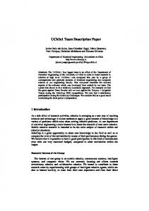
Since 1999, the CoPS-Team (Cooperative Soccer Playing Robots) successfully took part in RoboCup tournaments. The research objectives of our group are multi-agent software design principles for autonomous mobile robots regarding multi-agent data fusion and distributed plan execution. In recent years, a highly modular software architecture was developed [BKL03] which allows the integration of arbitrary data processing modules. Selected parts of the local world model data of each agent are shared among the team and used for a consistent view on the current game situation. During the last year, we developed a new holonomic robot platform to substitute the former Nomadic Scout platform which had a differential drive. The first successful use of the new robot platform was at the RoboCup 2004 in Lisbon. Figure 1 shows the general setup of the agent software architecture used by the CoPS players. The basic principle of the software architecture is to have a set of generic data processing units for all the different tasks throughout the entire architecture. All data processors perform read and write operations on a central world model data container. The architecture is similar to a blackboard design [Bus96]. The number of these data processors is not limited, the system can therefore easily be extended by new functionality adding further data processing elements. The software architecture is structured into three layers, one responsible for the execution of actions, a second one for the storage and administration of data objects and a third one concerning the processing of sensory and communicated data for generating an accurate model of the current game situation.
Each layer consists of three levels of abstraction: 1. The Actuator-/Sensor Level is concerned with the low-level processing of sensor data and the extraction of basic features (e.g. blob detection, etc) at the world modeling layer. At the execution layer, the Pilot component is responsible for controlling the robot without consideration of the environment like e.g. obstacles. Its main functionality is to provide an abstraction from the kinematics of the underlying robot platform by a control interface based on rotational and translational velocities and accelerations. 2. The egocentric level defines a set of common basic capabilities in the execution layer, like approaching, dribbling or shooting a ball. Several data processing elements are responsible for the localization, tracing the status of the current local situation of the robot (e.g. when a goal area was entered) and a rudimentary object tracking. 3. At the shared “team” level the control of the team strategy is done. The action selection process takes the state of other players of the team into consideration to achieve a coordinated team behavior. At the world modeling layer, the distributed local views of the agents are fused to achieve a higher degree of consistency for the evaluation of the current situation (e.g. the current ball position and its velocity vector).
Fig. 1. Robot Software Architecture
The rest of this paper is organized as follows: Section 2 presents the improvements of our new modified hardware platform which is going to be used in the
upcoming tournaments. Then an outline of our current local sensor data evaluation mechanisms and self localization routine is given in section 3. Section 4 describes the currently used methods for the team behavior plan execution. Section 5 finally concludes.
2
The Hardware Platform
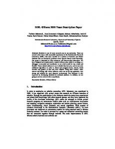
A new model of a mobile robot is completely designed and constructed at the University of Stuttgart in order to achieve the required characteristics for the RoboCup scenario and as a generic hardware platform for mobile robotic research and teaching.
(a)
(b)
Fig. 2. The 2004 (a) and the current (b) robot setup
The dynamical and kinematic characteristics of the design allow for a high maneuverability in the field. The 3D mechanical CAD drawings were done with Auto-CAD and the mechanical parts are completely manufactured at our university. Each robot is equipped with 3 omni-wheels, each of them driven by a 90W DC motor. Gearboxes with reduction ratios of 14:1 are used to reduce the high angular speeds of the motors (7000 rpm) and to amplify the wheel’s mechanical torques.
The velocity feedback is done by using 500 ppr digital incremental encoders. The velocity of the wheels is controlled by a 3-channel microprocessor based DC motor controller (developed by AiS Fraunhofer) which has a RS232 communication link with the host computer on-board. The controller reads the pulse trains from the motor encoders and produces amplified PWM output voltages for the motors based on a PID algorithm. The result is a mobile robot with maximum linear speed of 2.5m/s and acceleration of 3.5m/s2 . The robot is equipped with a laptop on which the sensor data processing, the control and the communication and data exchange is performed. Various types of digital sensors can be installed on the robot. We did experiments with various digital cameras, a compass sensors and accelerometers. The communication hardware between the sensors and the laptop can be done through USB, RS232, or IEEE1394 (FireWire). It is also possible to add analog sensors by adding a digital/analog converter card on the PCMCIA slot of the computer. A pneumatic kicker is installed on the robot which is supplied by a small air pressure tank.
3
Sensor data processing and self localization
Our robot platform is equipped with a omnidirectional vision system consisting of a digital camera (FireWire) and a hyperbolic mirror. The main parameters to be chosen are the height of the mirror and the distance between the mirror and the camera. They also determine the viewing angle of the lens for a full-size image of the mirror. As a new addition, a compass sensor is added which provides information about the orientation of the robot. The compass system is a magnetoresistive sensor. New extensions of the software facilitate the system to fuse both camera and compass data to enhance self-localization and the planned object tracking. First experiments with an acceleration sensor showed that such a device needs sophisticated evaluation algorithms and cannot be used in a “straight-forward” way. 3.1
Environment Sensing
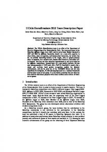
For almost all tasks we need information about the environment and especially a good estimation of the (relative or absolute) position of objects within the field. To find the position of objects relative to a robot, we use the standardized colors of the scenario. For some objects also other features are given e.g. the shape of the ball, or white lines for field boundaries. The whole image processing is encapsulated in a special filter architecture. The data flow can be visualized by a graph (Fig. 3). The filter graph describes a modular system to connect certain operations on an image. An operation is executed if all needed predecessors have finished and therefore all input data are available. Using a filter architecture allows to change image operations very fast without modifying all parts of the image processing software. To enhance the capabilities of the image processing
0
Capture 0
1
0
MidPoint 0
1
0
1
2
3
ColorCalib 0
1
2
0
1
2
Freespace
0
1
2
0
1
2
Segmentation
CreatePolPic
0
0
1
2
0
1
2
0
1
2
GoalPolDetection
PolSegmentation 0
0
1
2
PolGPD
Fig. 3. Filter graph with different connected image processors
a special filter for tracking objects using the Condensation algorithm [IB98] was added. For a higher accuracy of the motion model for the Condensation algorithm the image data is fused with the orientation given by the compass. As a result, obstacles like robots are identified and tracked. An example of an image with recognized obstacles is shown in Fig. 4 To extract information from an image, there are 2 possibilities: First, the complete image is segmented using the calibrated colors of relevant objects, such as the ball or field lines. Secondly, only certain regions of the image are segmented as the condensation algorithm gives a prediction of possible regions of interest. If there is no prior information about an object, which is the case at starting situations or if a tracked object is lost, the full segmentation has to be done. Otherwise, only the relevant parts of the image are segmented. One of the most important tasks in robotic soccer is obstacle avoidance. The image processing algorithms have been expanded to track obstacles on the field of play. In the next future, we plan to improve the tracking algorithms by using specific shapes of the objects. This information could also be helpful to plan a path closer to the object. 3.2
Self-Localization
After experimenting with several algorithms for self localization like triangulation and Markov localization approaches with different sensor features, Monte
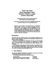
(a)
(b)
Fig. 4. Raw image of the omnidirectional camera (a), rectified image to get straight lines on the floor (b)
Carlo localization turned to be the most reasonable approach for the RoboCup scenario due to its robustness and flexibility even with temporary partial or total occlusion of relevant sensor features. The main visual features in the past year have been the detected white field lines on the field of play which are quite easy to detect even without making use of any color information. The field line information consists of detected points on a line which are extracted by a radial ray tracing approach where pixels are examined along a radial ray in the camera image starting from the center of the mirror. Since field lines cannot resolve the problem of the symmetry of the soccer field two positions in the field are equiprobable in the case of a kidnapped robot without any prior knowledge. A solution to this problem is to use the detected goals as a second feature in the Monte Carlo approach, by combining the probabilities of both the field line and the goal information as shown in Figure 5. At the left side of this figure the probability distribution of the line and goal features are shown where a darker color corresponds to a higher probability. At the right side the sample distribution of the particle filter is shown for the position hypotheses in the field of play. The probability distribution of the field lines is obviously more accurate but results in two equiprobable hypotheses. The goal feature is much less accurate but favors a unique positioning area in the field of play. A combination of both features with a lower weighted camera feature results in an accurate and unique position hypothesis. At the previous RoboCup championships only the nearest detected field lines per radial ray were used for the localization which results in a similar approach
to a laser range scan in an indoor scenario, like in [Thr97]. Currently we are employing an approach according to [MWR04] for the field lines which makes use of all field lines detected per ray and uses a very memory efficient heuristic method for storing the expectation model of the environment. This approach turned out to be very robust for almost all situations in the RoboCup domain.
As an alternative to the detected goals for resolving the symmetry problem we are currently investigating the use of a new integrated compass sensor.
Fig. 5. Multi Feature Monte Carlo localization
4
Team behavior modeling
For the modeling of team behaviors we use a petri-net based formalism based on interaction nets [BML98]. The original form of interaction nets was modified to get a slightly simpler approach according to the requirements of the RoboCup scenario. In our approach, a place of the petri-net refers to a state where a certain action is performed, e.g. a dribbling of the ball. Markers represent agents which have a certain set of attributes referring to their world model data or the local state of the action execution. Transitions contain conditions on the attributes of the agents which cause a transition of the agent to a successor place when the transition conditions are fulfilled by the agent attributes. One petri-net is used for the specification of the whole team behavior with different agent markers passing through the net. Since the world model of an agent contains information on the state of its team mate agents, it is possible to define interdependent state transitions for a synchronized action execution within the team. Since interaction nets quickly grow in size when modeling complex team behaviors a modularization approach was followed also for these interaction nets. This is done by the definition of so called net modules which can be nested within each other. Each net module can be viewed as a simple action module from a top level view and only be refined when needed. Figure 6 shows a network model for a pass play interaction of two players with two nested net modules for the pass receiver role and the passing player (double outlined places). Below the main net the refined net modules are shown. The conditions within the transitions are not shown for the sake of simplicity but annotated according to their semantics. To model interaction nets, an editor was implemented which allows the graphical design of these nets and allows an export of the interaction net to XABSL [LBBJ04], a specification language for hierarchically structured finite state automata which was originally developed for the four-legged league by the German Team. XABSL code can be parsed and executed immediately by an execution engine which is provided along with the framework.
5
Conclusion and Outlook
After last year’s successful participation in the RoboCup, we decided to modify the hardware in order to be able to play with more than four robots. Our world modeling concept was used to implement and test new or improved methods for image processing, object tracking and localization. The filter architecture in the image processing module was expanded by an implementation of the Condensation algorithm. The modeling of a complex cooperative or single robot behavior can be done with a newly developed graphical editor with XABSL output. For the near future, we plan to make experiments with multiple object tracking, introduction of additional sensors and collaborative sensor data fusion.
Fig. 6. Example net for a passing scenario
References [BKL03] T. Buchheim, G. Kindermann, and R. Lafrenz. A dynamic environment modelling framework for selective attention. In IJCAI Workshop: Issues in Designing Physical Agents for Dynamic Real-Time Environments: World modeling, planning, learning, and communicating. IJCAI, 2003. [BML98] M. Becht, Muscholl K. M., and Paul Levi. Transformable multi-agent systems: A specification language for cooperation processes. In World Automation Congress (WAC), Sixth International Symposium on Manufacturing with Applications (ISOMA), 1998. [Bus96] Frank Buschmann. Pattern-Oriented Software Architecture. A System of Patterns. John Wiley & Sons, 1996. [IB98] M. Isard and A. Blake. Condensation – conditional density propagation for visual tracking. International Journal of Computer Vision, 29(1):5–28, 1998.
[LBBJ04] Martin L¨ otzsch, Joscha Bach, Hans-Dieter Burkhard, and Matthias J¨ ungel. Designing agent behavior with the extensible agent behavior specification language XABSL. In Daniel Polani, Brett Browning, and Andrea Bonarini, editors, RoboCup 2003: Robot Soccer World Cup VII, volume 3020 of Lecture Notes in Artificial Intelligence, pages 114–124, Padova, Italy, 2004. Springer. [MWR04] A. Merke, S. Welker, and M. Riedmiller. Line base robot localisation under natural light conditions. In ECAI 2004 Workshop on Agents in Dynamic and Real-Time Environments, 2004. [Thr97] S. Thrun. The museum tourguide project: Experiences with a deployed service robot. In Proceedings of the IEEE International Symposium on Computational Intelligence in Robotics and Automation, 1997.