Tech-note: ScrutiCam: Camera Manipulation Technique for 3D Objects Inspection Fabrice Decle∗ Universite´ de Bordeaux
Martin Hachet† INRIA Bordeaux
Pascal Guitton‡ Universite´ de Bordeaux
Figure 1: Camera movements provided by ScrutiCam.
A BSTRACT
Inspecting a 3D object is a common task in 3D applications. However, such a camera movement is not trivial and standard tools do not provide an efficient and unique tool for such a move. ScrutiCam is a new 3D camera manipulation technique. It is based on the “click-and-drag” mouse move, where the user “drags” the point of interest on the screen to perform different camera movements such as zooming, panning and rotating around a model. ScrutiCam can stay aligned with the surface of the model in order to keep the area of interest visible. ScrutiCam is also based on the Point-OfInterest (POI) approach, where the final camera position is specified by clicking on the screen. Contrary to other POI techniques, ScrutiCam allows the user to control the animation of the camera along the trajectory. It is also inspired by the “Trackball” technique, where the virtual camera moves along the bounding sphere of the model. However, ScrutiCam’s camera stays close to the surface of the model, whatever its shape. It can be used with mice as well as with touch screens as it only needs a 2D input and a single button. Keywords: Interaction, Navigation, 3DUI, 3D Camera Manipulation Index Terms: I.3.6 [Computing methodologies]: Computer graphics—Methodologies and techniques; H.5.2 [Information interfaces and presentation]: User interfaces— Interaction styles 1
I NTRODUCTION
3D camera manipulation is an important problem in computer graphics (e.g. in games, CAD, simulation, etc.) This topic has been widely studied in the past years. Most 3D applications use a set of tools dedicated to camera manipulation. These tools perform basic camera movements such as translation, zoom and rotation, and barely evolved since the early years of computer graphic applications. As a consequence, achieving complex motions requires complex user manipulations. ∗ e-mail:
[email protected] † e-mail:
[email protected] ‡ e-mail:
[email protected]
In this paper, we propose a new 3D camera manipulation technique called ScrutiCam. The main idea of ScrutiCam is to easily control camera motions around an object by moving the areas of interest to the center of the screen. The view is then aligned with the surface of the model. As a consequence, ScrutiCam can be useful for inspection tasks. Inspection is commonly used in Computer-Aided-Design (CAD) applications, where users have to look at specific parts, zoom in and out or turn around some details of a 3D model. Such a task requires the use of several different tools. Switching between each of them is time consuming and users may feel lost if too many tools are available. Buxton [2] explains that each control switch divides the action in separate chunks, because the applied motor tension changes and the motion continuity is interrupted. This leads to higher separation into subtasks and therefore to higher cognitive load. Most 3D viewers combine these tools by assigning them to a specific button of the mouse, or to shortcuts. Touch screen devices, which are controlled by touching the screen, emulate a left mouse button click on the touched location. As a consequence, standard techniques can not be used on such devices without using a tool selection user interface, such as menus, toolboxes or gestual commands, which may be inefficient. The number and availability of touch screen based devices has increased recently. Today, ergonomics are changing and the standard “keyboard and mouse” configuration is evolving. Sketch based applications have appeared recently. In such applications, the user’s gestures are interpreted as contours of 3D models[9, 6] or as commands for the application[5]. Some 3D navigation techniques also use these features, such as Navidget[3] or UniCam[10]. Both use sketched-based commands to control a 3D virtual camera. They also use the “Point Of Interest” metaphor[8], where the users select on the screen plane the area of interest, in order to go to that location. However, if such techniques are well suited for navigating in large environments, they can be harder to use for precise camera movements, as required when inspecting details in close views. Inspection of 3D models requires an elementary camera movement: rotating around the whole model. In most 3D applications, this is done by using a “trackball” metaphor: the 3D scene is set inside a virtual sphere, and the camera is moved along the surface of the sphere. Some studies [1, 4] describe standard trackball techniques. This approach has some issues. The first one concerns the choice of the pivot point. Several points can be used, for example the center of the 3D world, the center of the selected object, or a user-selected point. As a result, users may have to switch between each possible
pivot point, or deal with an inappropriate pivot point chosen by the application. The second drawback of the trackball approach is that it is inappropriate for elongated models: as the camera moves along the surface of a sphere, the distance from the user’s point of view to the surface of the model is not constant, which potentially leads to incongruous camera movements. Finally, the camera always looks towards the center of the virtual sphere, and it is thus impossible to look in another direction without switching to another tool. This can be particularly inappropriate if the model is concave, as the camera cannot look to the sides of the concavity. Trackballs are useful when the view does not have to be close to the model. As a result, proximal object inspection requires the use of several tools to realize some tasks such as closely observing a model while turning around it. HoverCam [7] addresses this issue by providing a “hovering” camera, enabling easy proximal object inspection. It is based on a “closest point search” algorithm, which determines the next look-at point of the camera. As the distance from the camera to the look-at point is constant, the camera moves along the surface of the model, and smoothly rotates around its edges. The main drawback of this technique is the “closest point search” algorithm, which is time consuming. Consequently, it is inappropriate for low-end computers, where the computational power is limited, such as mobile devices. Moreover, searching for the closest point on a complex scene, with several objects, can increase the complexity of the algorithm. Finally, as HoverCam’s algorithm searches for the nearest point in the neighborhood of the current camera location, and computes a new camera position and orientation from that point, the user can not move to distant point without trying to find a path that will lead him or her to the desired location. We propose a 3D camera manipulation technique for proximal object inspection called ScrutiCam. It can be used with any 2D input, such as mice or touch screens. ScrutiCam operates thanks to an image-based algorithm. Consequently, it does not depend on the complexity of the scene. Moreover, as it requires the user to select his or her point of interest, it allows both proximal and distant camera movements. 2 2.1
S CRUTI C AM Overview
ScrutiCam is a 3D camera manipulation technique designed for inspection tasks. The user grabs his or her point of interest and moves it towards the center of the screen in order to align the camera viewpoint with the normal vector of the corresponding area. The center of the screen can be reached easily as an arrow shows the direction to follow (see Figure 4). If the user moves in any other direction, the camera is translated so that the selected point is still projected on the user’s cursor position. 2.2
Surface analysis
Standard camera control techniques are usually based on the position of the center of the studied model. As an example, this 3D point can be used as the pivot point of the trackball technique. However, such a strategy may not be optimal, especially on large models, where the center point may be far away from the current view. Rather than considering the center of the model, ScrutiCam uses the visible surface of the model in order to compute camera motion paths. The analysis of the model’s visible surface can provide
Figure 2: Movements to the center of the screen aligns the view to the target area. Movements in other directions translates the camera along the screen plane.
useful information, such as the normal vector of the surface, or the presence of edges and contours. ScrutiCam uses such information about the model’s visible surface, but only considers the surface surrounding the point of interest of the user. When a CAD engineer is working on a 3D model, for example when painting over the surface or when taking a careful look at a particular detail, he or she often needs to work on an area or interest. With ScrutiCam, the area of interest is defined by selecting a target point on the surface of the model. ScrutiCam then considers the surface of the neighborhood of this target point in order to compute a target view (i.e. a camera position and orientation that depend on the area of interest). This view is computed from information provided by the surface around the target point: the average ~ , which defines the orientation of the neighbornormal vector N hood of the target point, and the presence of contours. The method used to estimate the average normal vector is detailed in section 3. We consider the neighborhood of the point of interest rather than using the normal vector of that point (read from a fragment shader for example) in order to smooth irregular surfaces: if the continuity of the model’s surface is not C 1 , the angle between two close normal vectors of the surface may be high. In this case, two target points that are near each other can lead to two distant camera locations. Figure 3(left) shows that issue, which would be very disturbing for the user, as he or she could not predict where the camera would go. Using the average normal vector addresses that issue (see Figure 3(right)). The presence of contours and edges in the neighborhood of the target point gives informations about discontinuities on the surface of the model or about the presence of different objects near the area of interest. As a result, if a contour is detected, we use this information to provide a normal vector that will lead to a target camera that faces the edge of the model. 2.3
Control and camera movements
Each action that is achieved with ScrutiCam is based on the “clickand-drag” approach: once pressed, the button is held and the mouse (or the stylus or the finger) is moved. The “click-and-drag” approach is frequently used to move 2D objects, for example desktop icons or shapes in a 2D drawing application. This gesture is appropriate in touch screen based applications because they benefit from a direct mapping from finger to cursor : the mouse cursor is always beneath the user’s finger. As a consequence, the manipulation is more direct and seems more intuitive. We wanted ScrutiCam to use a direct mapping from finger position to the model manipulated, so
Figure 3: Normal vector issue. Left: when computing the exact normal vector of the surface. Right: when computing the normal vector on the neighborhood of the target point.
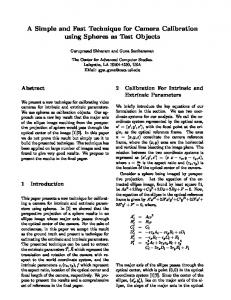
the target area selected by the user remains under his or her finger while interacting. ScrutiCam requires the user to select a point on the screen plane. This 2D point, and its neighborhood, are used to compute the aver~ , and the resulting target view. The orientation age normal vector N ~ of the target view equals to the opposite of N ~ . The camera poO sition P of the computed view is set along the line defined by the ~ . The distance from the surtarget point and the normal vector N face of the model to the target camera position can be defined by the user before doing the “click and drag” move, by clicking once on any point of the 3D scene. The distance from the current camera location to the selected point defines the distance that will be used to compute the target camera position. Once the target view computed, a path from the current camera to the target camera is computed as a linear interpolation of the camera position from the current camera position P0 to the target camera position P1 . Let t be the percentage of advancement of the camera along the path, P (t) = P0 + t ∗ (P1 − P0 ), t ∈ [0; 1]. In order to move the camera along the path, the t parameter must vary from 0 to 1 (see Figure 4). If we analyze the on-screen position of the target point, we can see that: • At t = 0, the on-screen position of the target point corresponds to the initial on-screen selected point. • At t = 1, the camera is in front of the selected target point . As a consequence, the on-screen position of that point corresponds to the center of the screen. Consequently, in order to keep the direct mapping from the cursor to the on-screen projection of the target point, the t parameter is controlled by the distance from the current cursor position to the center of the screen : t = 0 when the cursor is at the initial position, and t = 1 when it is at the center of the screen. In summary, ScrutiCam can be easily controlled, as it only uses two gestures: moving to the center of the screen to smoothly align the view to the surface of the model, and moving in any other direction to translate the view along the screen plane. 3
~ as the user Figure 4: Interpolation of camera position P and orientation O moves the cursor to the center of the screen. The camera is smoothly ~. aligned to the normal vector N
scene. Thus, we have tested ScrutiCam with a modified version of Vincent library1 , that allows reading the depth buffer. 3.1
Local model approximation
In order to compute the average normal vector, we use a “local approximation” of the model. This approximation is done right after the selection of the target point. As we need to consider the whole neighborhood of this point, and not only the neighborhood that belongs to the same object as the selected point, we decided to use an “image based” approach. Indeed, in a “geometry based” approach, this would mean knowing which objects and triangles are close to the selected point. This would be extremely time consuming. To overcome this issue, we compute the local normal vector via an image space approach. The main idea is to create a “pattern” on the image plane, and to project it into the 3D view around the target point. Then, we compute the average normal vector of the resulting mesh. The advantages of this method is that projecting some 2D points into the 3D scene is easy and fast, and does not require an a priori knowledge of the model. It is also independent of scene complexity, as opposed to HoverCam. Figure 5 shows the pattern we use in the screen plane (left), and the resulting projection on the model (right). The pattern’s size we use is 1/10 of the height of the window. 1 http://www.vincent3d.com
I MPLEMENTATION
ScrutiCam has been tested on various systems: an “Ultra Mobile PC” (with a touch screen), a PDA (with a touch screen too), a standard workstation, and a large touch screen (thanks to an e-Beam system). It uses OpenGL (for Windows and Linux versions) and a modified software version of OpenGL|ES (for the Windows Mobile version). Indeed, OpenGL|ES 1.1 does not support reading the depth buffer, which is necessary to project a 2D point into the 3D
Figure 5: Projection of the pattern used for the local model approximation.
Finally, we plan to evaluate the benefits of ScrutiCam compared to standard controls by conducting a user study. 5
Figure 6: Estimation of the border normal vector (top view)
3.2
Normal of side face
When the target point is near the border of the model, it may mean that the user wants to see its hidden side. We provide a way to do such camera movement, by considering the border in the normal vector computation. If some points of the pattern can not be projected into the 3D scene, it means that the target point is near the border of the model or near a hole inside it. In this case, we compute the “orientation” of the border, and set the average normal vector as the average of the triangles’ and the border’s normal vector. Figure 6 shows the triangles’ normal vector, the estimated border’s orientation and the resulting average normal vector. As a result, the user is able to see the hidden side of the model. 4
D ISCUSSIONS AND F UTURE W ORK
We asked members of our team to try ScrutiCam, in order to collect their feedbacks. They felt the technique easy to understand and to use. In particular, they were enthusiastic about using our technique. They liked being able to turn around a model with a simple gesture. Surprisingly, users who are experienced with standard 3D manipulation users had some difficulties using ScrutiCam at the beginning. They wanted ScrutiCam to react like the trackball, and were therefore surprised by the resulting camera movement. Once this step overridden, they understood how to use it. A leak point of ScrutiCam is that if the surface of the model is very irregular, the local normal vector may change often. As a result, some surprising camera movements may occur. To overcome that issue, we are working on another way to compute the average normal vector, based on the extraction of silhouettes and contours. Another problem occurs if the target point is selected near the center of the screen. In that case, the camera path will be short, resulting in a fast camera motion. This can be avoided by first moving away from the center of the screen, which translates the camera. At the moment, ScrutiCam is useful for inspecting 3D models. It is not well suited for exploring 3D scenes: as an example, when navigating in a 3D environment, users may want to stay on the ground. If the user selects a point on the ground, ScrutiCam would align the camera to its surface, and the resulting camera would be above the ground, looking down. We plan to extend the idea of ScrutiCam in the case of 3D navigation in virtual environments. New mobile devices such as Apple’s iPhone are equipped with multi-touch screens. They propose a new way to interact, by using only the fingers and some simple gestures to control the applications. This new way of interacting must now be applied to the manipulation of 3D environments. An interesting extension of ScrutiCam would be to use such a feature.
C ONCLUSION
In this paper, we introduced a new camera manipulation technique, called ScrutiCam. It allows proximal objects inspection with a 2D input device and a single mouse button. Proximal object inspection is a common but hard-to-perform task in 3D applications. Standard controls require heavy switching between different tools to achieve this task. With ScrutiCam, these camera movements only require one button, one tool, and one motion. It is thus well suited for touch screens, for which ergonomics are different from standard PC’s. ACKNOWLEDGMENTS
This work has been supported by the French research agency ANR. R EFERENCES [1] R. Bade, F. Ritter, and B. Preim. Usability comparison of mouse-based interaction techniques for predictable 3d rotation. In SG 2005, Proceedings of the 5th International Symposium Smart Graphics, pages 138–150, 2005. [2] W. Buxton. Chunking and phrasing and the design of human-computer dialogues (invited paper). In IFIP Congress, pages 475–480, 1986. [3] M. Hachet, F. Decle, S. Knodel, and P. Guitton. Navidget for easy 3d camera positioning from 2d inputs. In 3DUI 08, Proceedings of 2008 IEEE Symposium on 3D User Interfaces, pages 83–89, 2008. [4] K. Henriksen, J. Sporring, and K. Hornbaek. Virtual trackballs revisited. IEEE Transactions on Visualization and Computer Graphics, 10(2):206–216, 2004. [5] K. Hinckley, P. Baudisch, G. Ramos, and F. Guimbretiere. Design and analysis of delimiters for selection-action pen gesture phrases in scriboli. In CHI ’05: Proceedings of the SIGCHI conference on Human factors in computing systems, pages 451–460, New York, NY, USA, 2005. ACM Press. [6] T. Igarashi, S. Matsuoka, and H. Tanaka. Teddy: a sketching interface for 3d freeform design. In Proceedings of the 26th annual conference on Computer graphics and interactive techniques SIGGRAPH ’99, pages 409–416. ACM Press/Addison-Wesley Publishing Co., 1999. [7] A. Khan, B. Komalo, J. Stam, G. Fitzmaurice, and G. Kurtenbach. Hovercam: interactive 3d navigation for proximal object inspection. In I3D ’05: Proceedings of the 2005 symposium on Interactive 3D graphics and games, pages 73–80, New York, NY, USA, 2005. ACM Press. [8] J. Mackinlay, S. Card, and G. Robertson. Rapid controlled movement through a virtual 3d workspace. In Proceedings of the 17th annual conference on Computer graphics and interactive techniques, pages 171–176. ACM Press New York, NY, USA, 1990. [9] R. Zeleznik, K. Herndon, and J. Hughes. Sketch: An interface for sketching 3D scenes. In ACM Transactions on Graphics, Proceedings of SIGGRAPH, 1996. [10] R. C. Zeleznik and A. S. Forsberg. Unicam - 2d gestural camera controls for 3d environments. In Proceedings of Symposium on Interactive 3D Graphics, pages 169–173, 1999.